
No. 129,010 – Improvement In Dado-Planes (Rufus H. Dorn) (1872)
UNITED STATES PATENT OFFICE.
_________________
RUFUS H. DORN, OF PORT HENRY, NEW YORK.
IMPROVEMENT IN DADO-PLANES.
_________________
Specification forming part of Letters Patent No. 129,010, dated July 16, 1872.
_________________
Specification describing a new and Improved Extension Plane, invented by RUFUS H. DORN, of Port Henry, in the county of Essex and State of New York.
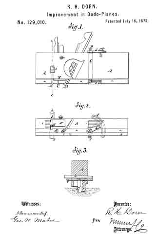
Figure 1 represents a side view of my improved extension plane; Fig. 2 is a bottom view of the same; and Fig. 3, a vertical transverse section on the line c c, Fig. 1.
Similar letters of reference indicate corresponding parts.
The object of this invention is to produce a grooving-plane which can be adjusted without change of knives, to cut narrower or wider grooves; and the invention consists in the application, to the plane, of a pivoted cutting-blade which can be swung more or less to one side to enlarge the scope of its action. The invention also consists in several other details of improvement, and in the combination with the swinging blade of a laterally-adjustable spur or marking blade, which must be set in accordance with the position of the swinging blade.
A in the drawing represents the body or block of the plane, made of wood or metal, and containing the ordinary planing-knife B, and double-pointed marking-spur C, in front, like every ordinary plane. The knife B and marker C extend across the full width of a rib, a, that projects from the bottom of the plane, and are therefore adapted to cut a groove of exactly the width of the said rib. D is a vertical arbor extending through the plane A, and through the rib a, and carrying a horizontal cutter, b, at its lower end. For the reception of this cutter b, a recess is provided in the rib a. When the arbor D is turned so as to swing the cutter b laterally, as in Fig. 2, the latter will thereby enlarge the cutting width of the plane in as far as its cutting-edge projects from the rib a. The larger the angle, therefore, at which the cutter b projects from the rib or, the wider will be the groove cut. The arbor D carries a slotted segment, d, at its upper end, by which the arbor and its knife may be set to any desired position. Through the segment passes a screw, e, which enters the plane for locking the cutter b in any position to which it may be swung. The arbor D is also vertically adjustable in the plane to compensate for wear and set the blade b to greater or less depth; and the blade is held at the desired height by a set-screw, f or its equivalent. E is a laterally-adjustable spur or marker, arranged on a transverse head, g, in front of the arbor D. It is set in line with the point of the blade b, and cuts through the stuff vertically, and thus defines exactly the width of grooves to be cut by the plane. The head g extends entirely through the plane A laterally, and can therefore be moved from either side to set the marker E. A wedge h, above the head g, serves to clamp it in any desired position, as is clearly indicated in Fig. 3. The marker E is attached by an adjustable union, in the form of a screw, to the head g, so that when the marker wears, or its vertical position requires change, it may be conveniently adusted. F is a vertically-adjustable gauge or support to regulate the depth of the out of the plane, and also support the marker E. The shank of the gauge F extends through the plane, and the gauge is adjusted from the top thereon and is held in the desired position by the lateral set-screw x. The position of the marker E is directly in front of the gauge, and in the use of the plane the force applied carries the marker against the gauge, which supports the marker and keeps it in proper position. The bottom of the plane is provided, in connection with the marker E and with the cutter b, with graduating scales or indexes i i, which represent the width of groove that may be cut, on which indexes the blade b and marker E can be set with great exactness, so that their respective positions will correspond with each other.
Having thus described my invention, I claim as new and desire to secure by Letters Patent —
1. The combination, in a plane, of the cutters B b and markers C E, arranged to operate together in the manner described.
2. The cutter b, providedwith arbor D, combined with the slotted segment d, as and for the purpose set forth.
The above specification of my invention signed by me this 12th day of January 1872.
RUFUS H. DORN
Witnesses;
T. B. MOSHER,
GEO. W. MABEE.