No. 679,702 – Spokeshave (Walter D. Murray) (1901)
[paiddownloads id=”554″]679702


UNITED STATES PATENT OFFICE.

_________________

WALTER D. MURRAY, OF PORTLAND, MAINE, ASSIGNOR,
OF ONE-HALF TO WALTER ACKROYD, OF SAME PLACE.

SPOKESHAVE.

_________________

SPECIFICATION forming part of Letters Patent No. 679,702, dated July 30, 1901.
Application filed May 31, 1900. Serial No. 18,627. (No model.)

_________________

To all whom it may concern:

Be it known that l, WALTER D. MURRAY, a citizen of the United States, residing at Portland, in the county of Cumberland, in the State of Maine, have invented certain new and useful lmprovements in Spokeshaves, of which the following is a specification.

This invention relates to that class of wood-working planes known as spokeshaves.

One object of the invention is to provide a spokeshave with a detachable reversible sole-piece, either edge of which may be used to vary the form of the spokeshave to adapt it for either concave or straight work.

Another object of the invention is to provide simple and effective means for raising and lowering the blade, whereby either end thereof may be moved as desired independently of the other to seen re accuracy of adjustment.

Another object is to provide improved handles for the spokeshave for insuring a better grip and a steadier working tool.

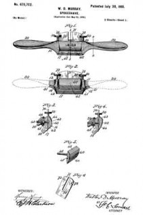
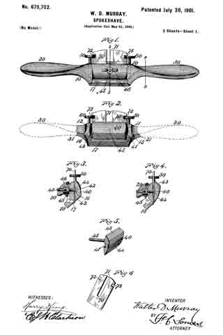
Figure 1 of the accompanying drawings represents a front elevation of this spokeshave. Fig. 2 represents a rear elevation thereof. Fig. 3 represents a central transverse section on line 3 3 of Fig. 1. Fig. 4 represents a similar section with the sole-piece reversed. Fig. 5 represents a perspective view of the detachable sole-piece. Fig. 6 represents a perspective view of the blade or cutter. Fig. 7 represents a rear elevation of the stock, the detachable sole-piece being removed. Fig. 8 represents another form of connection between the blade and the adjusting-screws therefor. Fig. 9 represents an end view of the stock, one of the handles being shown in section on line 9 9 of Fig. 1.

The same reference numbers indicate corresponding parts in all the figures.

In the form of spokeshave illustrated in the accompanying drawings a body or stock 10, having handles 20 and 30 at its opposite ends, is recessed at its back to receive a detachable sole-piece 40. The recessing of the stock forms a rear bed for the blade and shoulders 11 and 12, against which the ends of the sole-piece 40 abut. These shoulders 11 and 12 are provided with screw-threaded sockets 13 and 14, adapted to receive headed screws 50 and 60, respectively, the object of which will be hereinafter described. This stock is provided with a slot 17, through which the shavings pass. Means are provided on the stock and sole-piece for adjusting the latter incorrect position, and these means may consist of lags on one part and notches in the other. When constructed as here shown, the stock 10 is provided at the opposite ends of its recessed bed with lugs 15 and 16, adapted to engage notches 41 and 42, formed in the opposite ends of the sole-piece 40, whereby the proper adjustment of the sole-piece is accomplished.

The detachable sole-piece 40 is preferably constructed with its opposite edges in different forms, being shown as provided with a flat edge 43 and with a rounded edge 44,and either edge may be used to vary the shape of the spokeshave, as desired, by reversing the sole-piece.

Suitable means are provided for fastening the detachable sole-piece to the stock. In the form shown this sole-piece 40 has a screw-threaded shank 45 extending at right angles from the center of its inner face. This shank 45 may consist of a screw passed through the sole-piece or it may form a part of a bolt, the sole-piece 40 constituting the head thereof. This shank or bolt 45 extends through a perforation 18 in the stock 10, and the outer end thereof is engaged by a thumb-nut 46, which firmly clamps the sole-piece to the stock.

A blade 70, having a longitudinal slot 71 therein, is disposed in the recessed portion of the stock; 10, between it and the sole-piece 40. The bolt 43 of the sole-piece passes through the slot 71 before entering the perforation 18 of the stock, and the screwing down of the thumb-nut 46 thereon clamps the knife 70 firmly in position between the stock and the sole-piece. This blade 70 is provided at its opposite ends, near its top, with means for engaging the adjusting-screws 50 and 60, respectively. In the form shown in Figs. 1 and 2 these means consist of notches 72 and 73. In the form shown in Fig. 8 they consist of lateral lugs 74, which engage grooved or double heads 51 and 61 on the adjusting-screws. This blade may be adjusted at any desired height by simply turning the screws in the direction desired, and either end thereof may be independently raised or lowered to secure accuracy of adjustment by raising or lowering the screw connected therewith. Concave recesses 21 and 31, disposed substantially in a vertical plane and at right angles to the sole of the shave, are formed at the ends of the stock and extend through the adjacent portions of the handles 20 and 30, on the rear side of the latter. These recesses serve as finger-rests for the index-fingers when the shave is grasped in the hands and afford a better grip for the operator and a steadier working tool.

Either the means for adjusting the blade, the peculiar form of handles, or the detachable sole-piece may be applied to any adaptable form of spokeshave.

I claim as my invention —

1. A spokeshave having a detachable rear sole-piece serving as a clamp for the blade.

2. A spokeshave having a detachable reversible rear sole-piece.

3. A spokeshave having a reversible rear sole-piece provided with edges of different forms.

4. A spokeshave provided with a reversible rear sole-piece having edges of different forms, one of said edges being flat and the other rounded.

5. A spokeshave comprising a recessed stock, a blade adapted to fit in said recess, a reversible sole-piece also adapted to fit in said recess behind said blade, said stock being provided with means for engaging said sole-piece, and means for securing the blade and sole-piece to the stock.

6. A spokeshave comprising a stock provided with a recess at its back, a reversible sole-piece, adapted to fit in said recess, interlocking means on said stock and sole-piece, a blade disposed between said stock and sole-piece, and means for securing said sole-piece and blade to said stock.

7. A spokeshave comprising a stock provided vvith a recess at its back and lugs at opposite ends of said recess, a reversible sole-piece adapted to fit in said recess and provided with notches adapted to engage said lugs, a blade disposed between said sole-piece and stock, and means for securing said blade and sole-piece to said stock.

8. A spokeshave comprising a recessed stock having a perforation therein, a detachable rear sole-piece having a bolt attached thereto and adapted to extend through said perforation, a thumb-nut adapted to screw on said bolt and fasten the sole-piece in position, and a blade clamped between said sole-piece and stock.

9. In a spokeshave the combination of a stock provided with a blade-bed and with screvv-sockets adjacent to opposite ends of said bed, a blade provided with notches at its opposite ends, means for clamping said blade to said bed, and adjusting-screws disposed in said sockets and provided with heads engaging said lateral notches.

10. A spokeshave comprising, a stock and handles extending from opposite ends thereof, vertical concave recesses being formed at the ends of the stock and adjacent portions of the handles on the rear side of the latter, which recesses serve as rests for the index-fingers when the shave is grasped by the hands.

WALTER D. MURRAY.

Witnesses:
ALICE H. SULIVAN,
JOSEPH E. DANAHER.

No. 426,806 – Plane (Edmund P. Hann) (1890)

[paiddownloads id=”463″]426806


UNITED STATES PATENT OFFICE.

_________________

EDMUND P. HANN, OF PORTLAND, INDIANA, ASSIGNOR OF
ONE-HALF TO WILLIAM S. BAKER, OF SAME PLACE.

PLANE.

_________________

SPECIFICATION forming part of Letters Patent No. 426,806, dated April 29, 1890.
Application filed December 14, 1889. Serial No. 333,744. (No model.)

_________________

To all whom it may concern:

Be it known that I, EDMUND P. HANN, a citizen of the United States, residing at Portland, in the county of Jay and State of Indiana, have invented certain new and useful Improvements in Planes; and I do declare the following to be a full, clear, and exact description of the invention, such as will enable others skilled in the art to which it appertains to make and use the same.

This invention has relation to an improvement in planes; and it has for its object to provide means whereby the cut may be regulated without moving the bit and without the employment of springs and levers or other like objectionable devices.

The invention will be fully understood from the following description and claims, when taken in connection with the annexed drawings, in which —

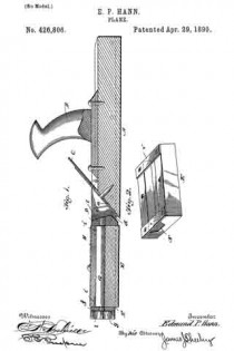
Figure 1 is a longitudinal sectional view of a plane constructed according to my invention, and Fig. 2 is a perspective view of the follower removed from the stock.

Referring to said drawings by letter, A indicates the stock, which may be mainly of any ordinary or approved construction and provided with a suitable handle B. The forward portion of the stock and in advance of the throat thereof is provided with a chamber, which is inclosed by the longitudinal side plates or walls of the stock, and also the forward transverse wall thereof. The body of the stock is provided at its forward end with a beveled seat a to seat the bit and the iron for securing the same in position.

The bit C is provided with the usual elongated slot b for adjusting the same; but, as will presently appear, such slot is only needed at first placing the bit after it has been removed for repairs or the replacement of a new one.

Secured transversely in advance of the throat d and to the side walls of the stock is a cross bar or block D, which is provided with an aperture e and serves as a bearing for one end of a cam-shaft, as will be presently explained. The forward transverse end wall f of the stock is also provided at a corresponding point with a similar aperture g to receive the forward or opposite end of said cam-shaft.

E indicates what I shall denominate the “follower.” This follower is provided with a truly planed engaging-face corresponding with the engaging-face of the main body of the stock and is arranged in the chamber or recess F. This follower may consist of a block, as shown, having a longitudinal recess in its upper face, as N, to receive the cam-shaft G, and across the opposite ends of this recess are strips i, which may be of metal or other suitable material. These strips are designed to furnish bearings for the cam-shaft, and the recess is preferably covered by a plate H or the like.

G indicates the cam-shaft. This shaft, which is designed to raise and lower the follower, has its opposite ends extended therefrom, as shown at l, and bear, respectively, in the aperture of the cross-bar D and the aperture in the forward transverse wall of the stock. These journal ends being arranged at corresponding points and eccentrically on the opposite ends of the shaft G, it will be seen that by simply turning the shaft the follower may be raised or lowered, as desired. By arranging the cam-shaft horizontally and causing it to exert its force transversely the follower can be raised or lowered evenly at all points by a single cam and without having to place any objectionable lugs or other attachments on the top or bottom of the plane-stock, and it also permits of a hand-wheel or other means of rotating it being placed on the forward end of the stock out of the way. The forward end of this shaft is provided with a small hand-wheel I for turning the same and manipulating the follower.

In operation it will be seen that when the bit has been set with respect to the lower face of the main body of the stock and it is desirable to get a cut of less depth it is simply necessary to turn the cam-shaft by the hand-wheel until the follower has been lowered to the desired point. To increase the depth of the cut the operation is simply reversed.

With a plane of this character it will be seen that there is little or no chance for lateral deviation of the cutter, as when once set it remains so, as the adjusting of the cut is performed by the follower and the manipulating cam-shaft.

While I have described minutely the parts in the exact construction and combination as illustrated, yet I do not wish to be understood as confining myself to such, as it is obvious that the object in view might be arrived at by other devices such as would suggest themselves to a skilled mechanic. It is necessary, however, that a cam and also a follower be used.

Having described my invention, what I claim is —

1. A plane having a practically fixed bit, in combination with a follower arranged in advance thereof and a rotatable cam-shaft having its axis arranged horizontally and exerting its pressure transversely thereto for raising and lowering said follower, substantially as specified.

2. The combination, with a stock having a I chamber in advance of the throat, a cam-shaft jonrnaled therein and adapted to exert pressure transversely to its axis of rotation, and carrying a hand-wheel on one end, of a follower suspended on said shaft and adapted to be raised and lowered thereby, substantially as specified.

3. The combination, with the stock, of the vertically-movable follower, the cam-shaft bearing in said follower, and bearings in the stock for receiving the opposite ends of the shaft, substantially as specified.

In testimony whereof I affix my signature in presence of two witnesses.

EDMUND P. HANN.

Witnesses:
WILLIAM S. BAKER,
DAVID V. BAKER.

No. 165,884 – Improvement In Bench-Planes (Hans Shogren) (1875)

[paiddownloads id=”249″]165884


UNITED STATES PATENT OFFICE.

_________________

HANS SHOGREN, OF PORTLAND, OREGON.

IMPROVEMENT IN BENCH-PLANES.

_________________

Specification forming part of Letters Patent No. 165,884, dated July 20, 1875; application filed March 19, 1875.

_________________

To all whom it may concern:

Be it known that I, HANS SHOGREN, of Portland, Oregon, and in the county of Multnomah of said State, have invented an Improvement in Bench-Planes, of which the following is a specification:

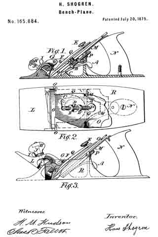
In the drawings, Figure 1 is a longitudinal section through or near the center. Fig. 2 is an inverted plan, looking upward from the bottom. Fig. 3 is a side elevation, partly in section, showing the movable front.

The nature and object of my invention are as follows: In many kinds of work it is necessary to bring the plane-bit O close against a glue-joint or projecting part of a rabbet, or other angular part rising above the surface to be planed, and with common planes this cannot be done, on account of the fore part of the plane in front of the bit, and after planing with them the end can only be finished with a chisel; but by the arrangement herein shown the work may be fully done by the plane itself. To accomplish this the fore part L of the plane R is hung on two screw-centers, G, situated one on either side of the plane opposite the opening for the shavings; and this part L is further provided with a knob, H, in which the nut and screw J are placed, and between H and L a small thumb wrench, I, is placed. The head of the screw J is a sort of eccentric or hook-shape, the sides of the screw-shaft being flattened in such manner that they ht the opening in the center of the wrench I.

Fig. 1 shows the plane when used as a common plane; and Fig. 2 shows the piece L closed in its place in front of the cross-rib K, which is a part of the back portion ofthe plane R. The head of the screw J is hooked. To change this, and put it in the position shown in Fig. 3, the following operation is gone through: First, the knob H, which carries the nut of the screw J, is turned so as to unscrew the nut, and while holding the knob H between the thumb and finger of one hand the other thumb turns the wrench I in such way as to still further unscrew the screw J, and this latter operation turns the screw half round, and disengages it from the cross-rib K. It may now be opened freely, as in the Fig. 3, or thrown entirely back on the top of the plane-iron, and in this position it may be used as now described. By looking at Fig. 2, and at the chip-opening in front of the bit O, an oblique line is seen crossing the under surface of the plane, and at its narrow end to run into the chip-opening. This is the joint between the front part L and the back part of the plane, so that if L were raised up or opened, as in Fig. 3, a portion of the chipway would be entirely open at the front, and half or more would have a narrow bearing in front of the plane-bit. In planing up to a projection this is so arranged that this part prevents the wood from lifting in front of the bit, and having planed to within a quarter of an inch or less of the object the plane is pushed sidewise, and in this way the chip is cut entirely out by the exposed part of the bit, the joint being so arranged that the bit is the foremost object on that side of the plane.

The next feature is the manner of fastening the bit O by means of the forked clamp Q, Fig. 2, screw E, and two pins, F, on theinside of the chip-opening, one on either side, so that the forked clamp Q passes under them somewhat after the manner of the wedge in a wooden plane, and to facilitate keeping Q in its place little hollows are formed on its upper surface, so that they will slightly engage with the pins F, and being so set under the pins F the screw E is tightened, and in this way the bit O is held firmly against its seat in the metal part R. The bit O is like those used in a common wood-plane, having at its back or under side the head of the clamp-screw D.

An arrangement for setting the bit O is as follows: A thumb-lever, A, projecting into the finger-opening in front of the handle N turning on a center, O, Fig. 2, carries a pitman-screw, P, in a joint of its shorter bent end. On the screw P are two nuts, B B’, which turn freely up or down, and are adjustable on the head of the clamp-screw D, and, being in proper adjustment, any movement of A raises the bit up or down. The center G is attached to the bottom of the plane, on the upper side, and beneath the bit O. A forked metal piece, M, Fig. 2, is fastened to the upper part of the handle N by a screw, and the corners or ends of the same to the metal part of the plane near the upper bearings for the bit O, and between these two bearings a vertical web (a bent part of this same piece M) extends, through which a hole is made forming the upper support for the screw P, and all together forming a firm support for the handle N. The whole plane is made of iron or other metal, except the handle N and knob H, which are of wood. The joint between the front and back part is neatly fitted, and the bottom is planed up neat and straight.

I claim —

A bench-plane, provided with the adjustable hinged part L, substantially as and for the purpose specified.

HANS SHOGREN.

Witnesses:
H. M. HUDSON,
CHAS. B. TALBOT.