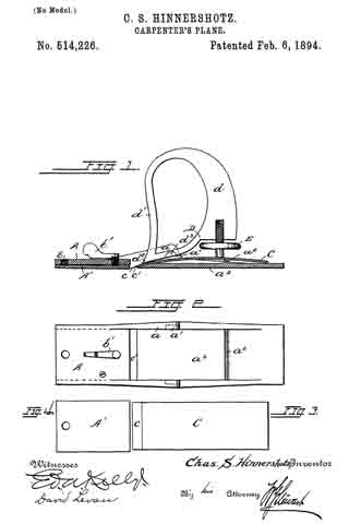
No. 514,226 – Carpenter’s Plane (Charles S. Hinnershotz) (1894)

[paiddownloads id=”501″]514226


UNITED STATES PATENT OFFICE.

_________________

CHARLES S. HINNERSHOTZ, OF READING, PENNSYLVANIA.

CARPENTER’S PLANE.

_________________

SPECIFICATION forming part of Letters Patent No. 514,226, dated February 6, 1894.
Application filed February 4, 1893. Serial No. 460,977. (No model.)

_________________

To all whom it may concern:

Be it known that I, CHARLES S. HINNERSHOTZ, a citizen of the United States, residing at Reading, in the county of Berks, State of Pennsylvania, have invented certain Improvements in Carpenters’ Planes, of which the following is a specification.

My invention relates more particularly to bench planes adapted to be constructed wholly or largely of metal.

The main objects of the invention are, first, to simplify the construction, and the setting and fastening of the bit, and second to make the operation more satisfactory.

The novel features of the invention are fully described in connection with the accompanying drawings and are specifically pointed out in the subjoined claims.

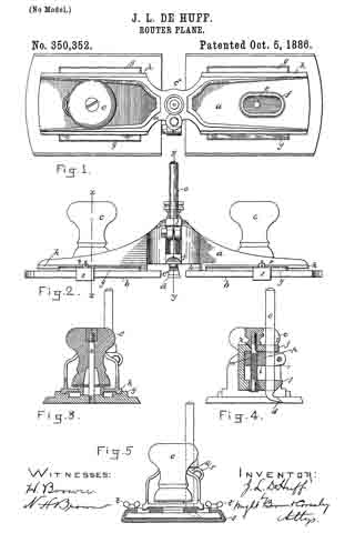
Figure 1 is a longitudinal section of a plane embodying my improvements. Fig. 2 is a plan view of the stock or bed. Figs. 3 and 4 are separate views of the bit-iron and of the adjustable spring plate which forms a portion of the sole.

The stock or bed A as shown is a casting, of which the main part of the base plate a3 forms the rear portion of the sole while the part of said plate forward of the mouth c’ is raised to a higher plane and has secured to its under side by means of a screw bolt b at its forward end a spring plate A’, the rear free end of which extends to the mouth c’ and is capable of being pressed downward from its normal position by means of an adjusting screw b’. This adjustable plate thus forms the forward portion of the sole.

The bit iron C is a plain plate of steel ground to a cutting edge c and slightly curved. This is placed upon the upper face of the base plate a3 of the stock with which it may lie substantially parallel as shown, the curve however being sufficient to permit the cutting edge c to be projected through the mouth c’. It is clamped to the stock by means of a fastener D. This is provided with a clamping screw E as usual, which in pressing downward the rear end of the bit-iron upon the transverse rib a2 on the stock turns the fastener upon its fulcrum trunnions d3 which engage grooves a’ in the side walls a of the stock and causes the forward end d2 of the fastener to firmly clamp the forward end of the bit iron to the stock. This fastener is provided with a handle d and with a break-iron d’ which is carried upward in front of the handle and serves to effectually turn the shavings to one side.

By my improved construction I provide an exceedingly simple plane, very economical in manufacture yet more satisfactory in operation than any plane of its class with which I am acquainted.

Having thus fully described my invention I do not limit myself to the exact construction shown, but —

What I claim is —

The herein-described carpenter’s plane, consisting of the stock or bed, having the portion of the sole atthe rear of its mouth integral with it and the forward portion formed by a separate plate and adjustable to regulate the depth of the cut, said rear portion of the stock having a rib extending upward from its upper side; the curved bit-iron, extending through the mouth of the plane and engaging near its forward end the wall of said mouth and near its rear end the rib of stock; a combined handle and holder for the bit-iron, engaging the bit-iron at its forward end and fulcrumed to the stock near its said forward end; and an adjusting screw, engaging directly the handle at one end and the bit-iron at the other end, said screw serving to press downward and hold the rear end of the bit-iron against said rib and simultaneously to force and hold the forward end of the handle downward to clamp the forward end of the bit-iron against the stock, substantially as described.

In testimony whereof I affix my signature in presence of two witnesses.

CHARLES S. HINNERSHOTZ.

Witnesses:
ED. A. KELLY,
DAVID LEVAN.

No. 350,352 – Router-Plane (John L. De Huff) (1886)

[paiddownloads id=”414″]350352


UNITED STATES PATENT OFFICE.

_________________

JOHN L. DE HUFF, OF READING, MASSACHUSETTS.

ROUTER-PLANE.

_________________

SPECIFICATION forming part of Letters Patent No. 350,352, dated October 5, 1886.
Application filed February 20, 1886. Serial No. 192,667. (No model.)

_________________

To all whom it may concern:

Be it known that I, JOHN L. DE HUFF, of Reading, in the connty of Middlesex and State of Massachusetts, have invented certain new and useful Improvements in Router-Planes, of which the following is a specification.

My invention relates to planes used by pattern or cabinet makers, and particularly to what are known as “router-planes,” employed for grooving or channelling wood-work.

It is the object of my invention to construct a device of the character mentioned which shall be more serviceable than those heretofore employed, in that it will not be liable to become clogged or obstructed in its operations by shavings, may be readily adjusted to tools or plane-irons of different forms and sizes, and may have other points of advantage, all as hereinafter fully described, and subsequently pointed out in the claims.

In the drawings hereto annexed and forming a part of this specification, Figure 1 represents a top plan view of my improved router-plane, one handle being shown as removed; Fig. 2, a front view; Fig. 3, a vertical section on the line x x, Fig. 2; Fig. 4, a section on the line y y, Fig. 2; and Fig. 5, an end view.

Similar letters of reference indicate similar parts in all of the figures.

In the drawings, a represents the stock of the plane, b, the sole thereof, c, the handles, and d the cutting-tool or plane-iron. As shown, the sole is formed in two equal sections, adjustable longitudinally on the stock by means of a screw-threaded stem or stud, e, secured to the upper surface of each sole-section a, which stem or stud projects through an elongated slot, f, in the stock, and upon which the handles are secured by being screwed thereon, as clearly represented in Figs. 3 and 5. A washer is preferably interposed between the base of the handle and the upper surface of the stock. By the construction described the stem or stud e serves the purpose of attaching the handle to the stock, and, inconnection with the handle, of clamping the sole-sections b to the stock proper at any point thereon within the limit of its adjustment, and an open channel, c*, from front to rear of the plane, is formed between the sole-sections. Each sole-section is provided on its upper surlhce with ribs g, extending along the sides thereof, as shown in Figs. 1 and 5, and the under surface of the stock proper, at both sides of its center, is provided with ribs h h’, the sides of which ribs are adapted to slide in correspondingly shaped grooves formed in the ribs g on the sole. (See Fig. 4.) Rib h’ on the under surface of the stock is constructed to move between the ribs g to form a close joint or connection between the stock and sole, and thus avoid liability of shavings becoming caught between the parts and obstructing the operations of the device. Any other construction and arrangement of ribs g and h to answer the same purpose would be within the scope of my invention.

The stock is cast or otherwise formed with a chamber, i, at its center, and with lugs j j projecting laterally from above and below said chambered part. Holes k and l are bored through the upper and lower portion of the chambered portion, and rod m, fitted to turn in holes k, is extended therethrough, as clearly shown in Fig. 4. Said rod is screw-threaded on that portion passing through the chamber, and is so stepped in the lower portion of the stock proper as to turn or rotate in holes k, but not to move vertically therein, a head, n, being secured to the upper end of said rod, whereby it maybe rotated. The holes l in the lugs j are adapted to receive the stem o of the plane-iron or cutting-tool. The screw-threaded portion of the rod in passes through a corresponding screw-threaded hole in a traveler, p, within chamber i, whereby by turning said rod said traveler may be raised or lowered thereon within said chamber. Said traveler is provided with a split clamp-extension q, through which the stem of the plane-iron is adapted to pass, and in which it is adapted to be clamped or secured by means of a bolt passing through ears r of said split clamp portion.

It will now be understood that a cutting tool or iron of any character may be secured in the clamp of the traveler at any horizontal angle therein, and adjusted by means of the rod on to any desired height, while the sole parts b b of the stock can be adjusted to a position as close to or far from the tool as the size or form of the cutting portion of the planer-iron may require.

Experience has demonstrated that a router-plane constructed in accordance with my invention is serviceable in the highest degree in all the uses for which a tool of that character is designed, and that there is no liability of the device becoming clogged or obstructed in its operation by shavings or chips cut from the material being operated upon. The edges of the soles are given a sloping form, and a gage, s, grooved to fit said edges, is secured thereon by means of thumb-screws t, as shown in the drawings. This gage is adapted to operate against the edge of the material being grooved or channeled, by which means the groove may lie formed in different pieces, the material at precisely the same distance from the edge, all as will be readily understood by those skilled in the art.

I do not confine myself or expect to be confined to the precise form and arrangement of parts shown and described, as these may be changed without departing from the spirit of the invention.

What I claim is —

1. A router-plane having its sole portion formed in two parts, one or both of said parts being adjustable longitudinally on the stock to and from the side or sides of the planer-iron or cutting-tool, as set forth.

2. A router-plane provided with a planer-iron or cutting-tool adjustable vertically therein, and having its sole portion formed in two parts longitudinally adjustable on both sides of the planer-iron or cutting-tool, as set forth.

3. The router-plane having flanges h h’, formed on its lower surface, and sectional sole portions a, having ribs g formed on their upper surfaces, said flanges h being adapted to move on ways on said ribs, and means for clamping or securing said sole portions to the stock at any desired position on both sides of the planer-iron or cutting-tool, as set forth.

4. A router-plane having its sole portion
formed in two parts, slots formed in the stock proper, studs or rods secured to the upper surface of said sectional sole parts and projecting through said slots, means for securing the handles of the planer to said studs and at the same time adjusting the sole parts at any desired point on the stock on one or both sides of
the planer-iron or cutting-tool, as set forth.

5. The combination, with the stock provided with the chamber i and lugs j, having the holes k and l formed therein, of the rod m, traveler p, provided with the split clamp portion q, having ears n, the clamping-bolt in said ears, and the cutting-iron d, as set forth.

In testimony whereof I have signed my name to this specification, in the presence of two subscribing witnesses, this 10th day of February, 1886.

JOHN L. DE HUFF.

Witnesses:
ARTHUR W. CROSSLEY,
C. F. BROWN.

No. 310,163 – Plane (William F. Achenbach) (1885)

[paiddownloads id=”380″]310163


UNITED STATES PATENT OFFICE.

_________________

WILLIAM F. ACHENBACH, OF READING, PENNSYLVANIA.

PLANE.

_________________

SPECIFICATION forming part of Letters Patent No. 310,163, dated January 6, 1885.
Application filed September 15, 1884. (Model.)

_________________

To all whom it may concern:

Beit known that I, WILLIAM F. ACHENBACH, a citizen of the United States, residing at the city of Reading, county of Berks, State of Pennsylvania, have invented a new and useful Improvement in Planes, of which the following is a specification.

This improvement relates more particularly to carpenters’ bench-planes.

The object of the invention is to place in the hands of wood-workers, joiners, and others a plane which will dress smoothly cross-grained and knotty woods so finely that subsequent filling and scraping are rendered unnecessary. These results are attained by a very slight yet important alteration of the mode of dressing the face of planes, as will be explained further on.

Figure 1 is a perspective elevation of a smoothing-plane having my improvement attached thereto. Fig. 2 is a longitudinal section showing more clearly the improvement. Fig. 3 is a plan view of the face of the plane, showing the improvement. Fig. 4 is a plan and sectional view of the plane-bit preferably used in the plane. In all of which —

A represents the body of the plane; A’, the month of the plane; A2, the throat; B, the wedge; C, the bit; D, the usual cap for a double bit; E, a metal plate sunk in the face of the plane in advance of the mouth-opening; E’, a plate sunk in the face of the plane in the rear of the mouth.

The improvement is applicable to both jack and fore planes, and it will be found advantageous to apply it to the same; but it is particularly adapted to the smoothing-plane for finishing off veneers or any fine work in hard or soft woods. The usual custom is to smooth off as well as is practicable with the plane, then to use the scraper to finish up, supplementing the latter by a wood filling and a rubbing down with pumice-stone. With my improvement in the construction of the plane-face this is unnecessary, as a simple sandpapering after the plane leaves the work ready for varnishing.

The result of the improvement is that much more work can be done in a given time, and when done is of a superior character to all work hitherto produced by the use of the plane alone.

The construction of the plane is as follows, the description applying more particularly to a smoothing-plane, as shown: It will be seen that the elevation, as in Fig. 1, makes no disclosure of any change in the construction of the plane. The longitudinal section and the plan, Figs. 2 and 3, show metallic plates inserted permanently in the face of the plane. The plates are about one-half inch wide, and about one-fourth of an inch short of the width of the plane at the point of insertion, leaving, when inserted, about one-eighth of an inch of wood standing at each end of the metallic plate. The plates may be about one-eighth of an inch thick, and they are secured in place by countersunk-screws.

The plates having been placed as shown, one, E, with its edge coincident with the front edge of the month of the plane, and the other placed at about one-third of the length of the plane from its rear end, I dress the face of the plane, and metallic plate included, from the mouth-edge of the plate to the fore end of the plane, so that the fore end shall be about one-thirtieth of an inch lower than the mouth-edge of the plate, the face of the plane being reversed upon the bench. The space between the plates E and E’ may be level, but I prefer to have it slightly hollow — say about one sixty-fourth of an inch — and from the rear plate, E’, to the end of the plane I again drop the face, the plane-face being reversed to about one-thirtieth of an inch at the rear end below the level of the plate E’, the straight edge in both cases resting upon the inner edges of the plates E and E’.

For fore or jack planes the same depression of the face from the front and rear plates is maintained, but the space between the front and rear plates is kept at a dead level, and one or more intermediate plates inserted to insure uniformity of wear.

The use of the plates not only serves to maintain certain fixed points upon the face of the plane, but also serves to reduce the friction of the plane in operating the same.

Although an ordinary double-bitted plane-iron may be used in a plane constructed in accordance with my improvement, yet I find a plane-iron of a parallel thickness for the length of the cap to give better results. A parallel bit, as it wears and is thrust forward through the mouth of the plane, causes no change in the distance left between its face and the edge of the plate, while the thrusting forward of the usual tapered thickness bit as it wears away gradually enlarges the opening of the mouth, and will not permit of fine work being done. The plate E at the mouth should be so set relative to the bit C that the space left for the passage of the shavings should limit the thickness of the same to suit the character of work to be performed, and the plate E’ in all cases at about one-third of the length of the plane from its rear end, this plate marking that point upon the plane which I find from practical use to be that which is best adapted to give relief to the user in handling the same, and indicating by its position that portion of the plane-face lying between plates E E’, which is to be retained at or near a dead level, as already described. As the plane-face loses its original form from use, it must be renewed, which I find is best performed by rubbing down with a block of hard wood covered with fine flint sand-paper. For hard-wood veneers, &c., a clearance at front and rear (the straight edge resting upon the inner edges of the plates E E) of about one-thirtieth of an inch will be ample. For soft woods the clearance may be increased to one-twentieth of an inch.

In grinding up and sharpening the bit it should curve very moderately in its width, and should project very slightly above the face of the month-iron E. The slight elevation of the edge of the plate above the fore end of the plane gives the plane-bit a bite upon the wood with the slightest protrusion ofthe same.

In the use of a plane whose face is dressed in accordance with my improvement the operator will find that less exertion is required and more work is performed, from the fact that there is nothing to interfere with the bite of the bit upon the wood, whereas, with the ordinary plane, the face being a dead level from end to end, the bit must be projected beyond the face to a much greater extent to cut down the same depth of surface, and, owing to this greater protrusion of the bit there is more liability to catch and tear away the material when knots or cross grain intervenes, thus leaving the surface in a much rougher condition.

Having described my improvement and shown its construction and use, I desire to secure by Letters Patent the following claims thereon —

1. As an improved article of manufacture, a carpenter’s bench-plane provided with inserted metallic plates suitably secured in the face thereof, one, E, at and forming the fore edge of the mouth of the plane, and one, E’, at about one-third of the length of the plane from the rear end of the same, and dressing the fore and rear faces of the plane from said plates E and E’, as described, in combination with the plane A, wedge B. bit C, and cap D, as and for the purpose set forth.

2. In combination with carpenters’ fore, jack, and smoothing planes, having their faces dressed as described, the plates E and E’ with one or more plates intermediate thereto, recessed in said plane-faces, and suitably secured therein, substantially as shown, and for the purpose set forth.

WILLIAM F. ACHENBACH.

Witnesses:
THOMAS P. KINSEY,
F. PIERCE HUMMEL.