No. 406,605 – Carpenter’s Plane (Reinhard T. Torkelson) (1889)

[paiddownloads id=”451″]406605


UNITED STATES PATENT OFFICE.

_________________

REINHARD T. TORKELSON, OF WORCESTER, MASSACHUSETTS,
ASSIGNOR TO IVER JOHNSON, OF SAME PLACE.

CARPENTER’S PLANE.

_________________

SPECIFICATION forming part of Letters Patent No. 406,605, dated July 9, 1889.
Application filed November 23, 1888. Serial No. 291,675. (No model.)

_________________

To all whom it may concern:

Be it known that I, REINHARD T. TORKELSON, a citizen of the United States, and a resident of the city and county of Worcester, State of Massachusetts, have invented certain new and useful Improvements in Carpenters’ Planes; and I do hereby declare that the following is a full, clear, and exact description thereof, reference being had to the accompanying drawings, forming a part of this specification, and in which —

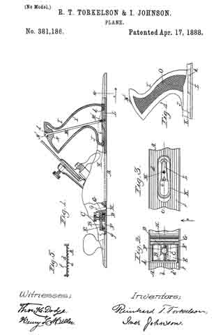
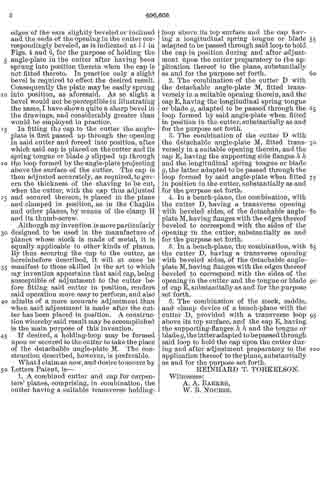
Figure 1 represents a side view, partly in section, of a bench-plane embodying my improvements. Fig. 2 is a plan of the lower part of the cutter with my improved cap secured thereon, as hereinafter more fully described. Figs. 3 and 4 are transverse sections through said cutter and cap, taken on lines a and b in Fig. 2, respectively, looking in the direction of the arrow in said figure. Fig. 5 is a central longitudinal section through the cutter and cap, taken on line c, Fig. 2; and Fig. 6 is a perspective view of the detachable angle-plate employed for adjustably fastening the cap to the cutter, as hereinafter specified.

To enable those skilled in the art to which my invention appertains to better understand the nature and purpose thereof, I will now proceed to describe it more in detail.

My said invention relates to improvements upon the carpenter’s plane patented by O. R. Chaplin in the United States under date of May 7, 1872, No. 126,519; and it consists of improvements in the construction of the cutter and cap, as hereinafter set forth.

In the drawings, the part A represents the plane-stock; B, its handle; C, its knob for holding the front end of the plane; D, the cutter; E, the cap; F, the supporting-saddle, fastened at its lower end to the boss G, projecting up and backfrom the bottom of the stock.

H is the clamp, having the lugs d upon each side adapted to catch under the sides of the saddle.

I is the thumb-screw for operating said clamp.

J is a screw-cam fitted to turn on the stationary pin e.

K is a half-nut projecting down from the upper end of the saddle and engaging with said screw-cam, and L is a lever for operating through the screw-cam and half-nut the saddle and cutter longitudinally.

Any further description of the old parts of the plane may be obtained, if desired, by reference to the patent previously alluded to.

My improvements in the cutter and cap are as follows: Instead of fastening the cap E to the clamp H, as in said Chaplin patent, it is in this instance fastened to the cutter D by forming a transverse opening f in said cutter to receive a transverse angle-plate M, which is passed up through the cutter from the under side, so as to form a holding-loop above the cutter. Through said loop is passed the longitudinal tongue or blade g, formed on the cap E, whereby said cap is held in position. The tongue or blade is made curving or bow-shaped lengthwise, so as to produce a constant pressure upward against the holding angle-plate when it is slipped under the same, and the cap is also provided with two flanges h h, one at each side of the tongue or blade, curved downward, and bearing at their ends upon the top surface of the cutter, the purpose of the latter being to hold the edge j of the cap elevated above the cutter to prevent injury to the cutting-edge of said cutter in the operation of placing the cap in position thereon. Although said flanges h h are preferable for the above purpose, I do not limit myself thereto, as the same result may be obtained by forming the cap so as to bear upon the cutter in a similar manner at any suitable point between the sides or edges thereof, said modification consisting simply in changing the positions of said bearing-points. The same will be readily understood without special illustration in the drawings. The angle-plate is held in position in the cutter against the upward pressure produced by the spring tongue or blade g by means of ears or projections k k, formed upon each end thereof, adapted to bear upon and hold against the under side of the cutter. Said ears are preferably recessed into said cutter, as is shown in Fig. 4, so as to bring the bottoms of said plate and cutter flush with each other. It is also preferable to make the edges of the ears slightly beveled or inclined and the ends of the opening in the cutter correspondingly beveled, as is indicated at l l in Figs. 4 and 6, for the purpose of holding the angle-plate in the cutter after having been sprung into position therein when the cap is not fitted thereto. In practice only a slight bevel is required to effect the desired result. Consequently the plate may be easily sprung into position, as aforesaid. As so slight a bevel would not be perceptible in illustrating the same, I have shown quite a sharp bevel in the drawings, and considerably greater than would be employed in practice.

In fitting the cap to the cutter the angle-plate is first passed up through the opening in said cutter and forced into position, after which said cap is placed on the cutter and its spring tongue or blade g slipped up through the loop formed by the angle-plate projecting above the surface of the cutter. The cap is then adjusted accurately, as required, to govern the thickness of the shaving to be cut, when the cutter, with the cap thus adjusted and secured thereon, is placed in the plane and clamped in position, as in the Chaplin and other planes, by means of the clamp H and its thumb-screw.

Although my invention is more particularly designed to be used in the manufacture of planes whose stock is made of metal, it is equally applicable to other kinds of planes. By thus securing the cap to the cutter, as hereinbefore described, it will at once be manifest to those skilled in the art to which my invention appertains that said cap, being susceptible of adjustment to the cutter before fitting said cutter in position, renders said operation more easy to perform, and also admits of a more accurate adjustment than when said adjustment is made after the cutter has been placed in position. A construction whereby said result may be accomplished is the main purpose of this invention.

If desired, a holding-loop may be formed upon or secured to the cutter to take the place of the detachable angle-plate M. The construction described, however, is preferable.

What I claim as new, and desire to secure by Letters Patent, is —

1. A combined cutter and cap for carpenters’ planes, comprising, in combination, the cutter having a suitable transverse holding-loop above its top surface and the cap having a longitudinal spring tongue or blade adapted to be passed through said loop to hold the cap in position during and after adjustment upon the cutter preparatory to the application thereof to the plane, substantially as and for the purpose set forth.

2. The combination of the cutter D with the detachable angle-plate M, fitted transversely in a suitable opening therein, and the cap E, having the longitudinal spring tongue or blade g, adapted to be passed through the loop formed by said angle-plate when fitted in position in the cutter, substantially as and for the purpose set forth.

3. The combination of the cutter D with the detachable angle-plate M, fitted transversely in a suitable opening therein, and the cap E, having the supporting side flanges h hand the longitudinal spring tongue or blade g, the latter adapted to be passed through the loop formed by said angle-plate when iitted in position in the cutter, substantially as and for the purpose set forth.

4. In a bench-plane, the combination, with the cutter D, having a transverse opening with beveled sides, of the detachable angle-plate M, having flanges with the edges thereof beveled to correspond with the sides of the opening in the cutter, substantially as and for the purpose set forth.

5. In a bench-plane, the combination, with the cutter D, having a transverse opening with beveled sides, of the detachable angle-plate M, having flanges with the edges thereof beveled ito correspond with the sides of the opening in the cutter and the tongue or blade of cap E, substantially as and for the purpose set forth.

6. The combination of the stock, saddle, and clamp device of a bench-plane with the cutter D, provided with a transverse loop above its top surface, and the cap E, having the supporting-flanges h h, and the tongue or blade g, the latter adapted to be passed through said loop to hold the cap upon the cutter during and after adjustment preparatory to the application thereof to the plane, substantially as and for the purpose set forth.

REINHARD T. TORKELSON.

Witnesses:
A. A. BARKER,
W. B. NOURSE.

No. 381,186 – Plane (Reinhard T. Torkelson And Iver Johnson) (1888)

[paiddownloads id=”435″]381186


UNITED STATES PATENT OFFICE.

_________________

REINHARD T. TORKELSON AND IVER JOHNSON, OF WORCESTER, MASSACHUSETTS.

PLANE.

_________________

SPECIFICATION forming part of Letters Patent No. 381,186, dated April 17, 1888.
Application filed September 14, 1885. Serial No. 177,099. (No model.)

_________________

To all whom it may concern:

Be it known that we, REINHARD T. TORKELSON and IVER JOHNSON, both of the city and county of Worcester, and Commonwealth of Massachusetts, have invented certain new and useful Improvements in Planes; and we do hereby declare that the following is a full, clear, and exact description of the same, reference being had to the accompanying drawings, forming a part of this specification, in which —

Figure 1 represents a vertical section through the ends of the plane on line b c, Figs. 2 and 3; Fig. 2, a top or plan view of the front of the plane; Fig. 3, a top or plan view of the rear section of the plane with the handle removed; Fig. 4, a side view of the handle and a small section of the plane-bed; and Fig. 5 represents a cross-section on line a, Fig. 1, looking in the direction of arrow 1.

To enable those skilled in the art to which our invention belongs to make and use the same, we will proceed to describe it more in detail, the nature of which consists, first, in certain improvements in the construction of an adjustable throat device; second, in improvements in the construction, whereby the handle may be detachably fastened to the bed; and, third, in an improved plane-bed, all as will be hereinafter more fully described.

In the drawings, A represents the bed of the plane,which is provided with corrugations d, the lower edges, e, of which are flat, and upon its upper side with round corrugations f. By this construction of the bed it can be made very light, while at the same time it is very stiff, thus utilizing in material, while at the same time rendering it light, and thus requiring less labor to operate it.

B represents an adjustable throat arranged upon the upper side of the plane-bed, through which a thumb-screw, C, passes into a set-nut, D. This nut works between two dovetail flanges, F F, (shown in full lines, Fig. 1, and dotted lines, Fig. 2,) the sides of the nut being made dovetailing to fit, and, consequently, while the nut can be moved back and forth it cannot be raised out of place until screw C and throat B are removed.

The body part E of the adjustable throat rests upon upright flanges g, (shown in full lines, Fig. 1, and dotted lines, Fig. 2,) and between the side flanges ofthe plane-bed F F. A forward projection, G, fits into the throat H, and which projection can be slid back and forth, as indicated in full and dotted lines, Fig. 1, and quickly adjusted, by means of the thumb-screw G, to give any desired opening to the throat H. This arrangement also leaves the under side of the bed of the plane smooth, thereby obviating the objections to the adjustable throats heretofore fitted to work on the under side of the plane.

I represents the handle of the plane, made of vulcanized india-rubber. It is made hollow, as seen at I’, and with a rounded base, J, to fit into a socket-piece, K, which in turn is made with an oblong slot, i, having edges inclined toward each other, so that said socket-piece K may be placed over the dovetail projection L on bed A, and when forced forward into the position shown in Fig. 1 it is securely held in said position vertically under the beveled edges k of said projection L. The base of handle I is now placed in the socket-piece K, and the screw-rod M passed down through the top and screwed into hole M’ in the dovetail projection L, thereby securing the handle firmly in position, while at the same time admitting of the detachment of said handle in an easy and expeditious manner. A forward projection, N, is cast upon the under side of the top of the handle, as fully indicated in Fig. 1, and a metal socket-piece, Z, is ntted into the top of handle I, to receive and hold the head N’ of the screw-rod M. The sides of the handle are made with a series of notches or corrugations, O, whereby when the handle is clasped in the hand the soft skin and flesh of the fingers will be pressed into the corrugations and notches on one side of the handle, while the skin and soft flesh of the hand at the base of the fingers will be pressed into the corrugations upon the opposite side of the handle. By this arrangement the operator can handle the plane much easier and with less exertion, particularly when he is obliged to hold up the plane to plane the edge of a piece of board, which is frequently required in the usual work of a carpenter. If the handle were smooth, a little perspiration or oil would require a great strain upon the fingers and cords of the hand to hold the plane from turning; but with the corrugations as made upon the sides of said handle the difficulty is obviated. If preferred, the socket-piece K may be cast with the bed of the plane and dovetail projections omitted.

We are aware that planes with adjustable throats have been used before, and we do not therefore claim said device, broadly.

Having described our improvements in planes, what we claim therein as new, and desire to secure by Letters Patent, is —

1. The combination of bed A, having the rear projection, L, upon the top thereof provided with the dovetail or bevel edges k, substantially as described, with the detachable socket-piece K, provided with an oblong vertical slot, i, having edges inclined toward each other, and adapted to be placed over said projection L, then forced forward and held vertically under the beveled edges k aforesaid, handle I, fitted at the bottom in said socket-piece K, and fastening-rod M, passed longitudinally through said handle and into bed A, substantially as and for the purpose set forth.

2. In a bench-plane, a throat-adjusting device located above the bed A in front of the throat H, consisting of said bed having the dovetail flanges F F and supporting-flanges g, in combination with the slide B, arranged over said flanges, and having the projection G next to said throat, the nut D, fitted to slide longitudinally over the bed between the dovetail flanges F F aforesaid, the latter holding said nut and slide B in position vertically, and thumb-screw C, fitted to turn in suitable vertical openings in the slide and nut, substantially as and for the purpose set forth.

REINHARD T. TORKELSON.
IVER JOHNSON.

Witnesses:
THOS. H. DODGE,
H. L. MILLER.

No. 381,141 – Bench-Plane (Iver Johnson And Reinhard T. Torkelson) (1888)

[paiddownloads id=”434″]381141


UNITED STATES PATENT OFFICE.

_________________

IVER JOHNSON AND REINHARD T. TORKELSON, OF WORCESTER, MASSACHUSETTS;
SAID TORKELSON ASSIGNOR TO SAID JOHNSON.

BENCH-PLANE.

_________________

SPECIFICATION forming part of Letters Patent No. 381,141, dated April 17, 1888.
Application filed October 31, 1887. Serial No. 253,829. (No model.)

_________________

To all whom it may concern:

Be it known that we, IVER JOHNSON and REINHARD T. TORKELSON, both of Worcester, in the county of Worcester and State of Massachusetts, have invented certain new and useful Improvements in Bench-Planes; and we do hereby declare that the following is a full, clear, and exact description of the same, reference being had to the accompanying drawings, forming a part of this specification, and in which–

Figure 1 represents a top or plan view of a bench-plane embodying our improvements. Fig. 2 is a side view thereof, partly in section. Fig. 3 is a bottom or face view of the plane. Figs. A and 5 are transverse or cross sections upon an enlarged scale, taken on lines a a and b b, respectively, in Fig. 1, looking in the directions indicated by the arrows above said figure; and Figs. 6 and 7 are enlarged detail views, Fig. 6 being a plan and Fig. 7 a side view of our improved throat-adjusting plate, hereinafter more fully described.

Our invention relates to metallic bench-planes, and more particularly to improvements in the means employed for regulating the width of the throat, as hereinafter more fully set forth.

Following is a detailed description of our invention with reference to the accompanying drawings.

The part A is the body or stock; B, the handle; C, the knife; C’, the usual means for holding said knife in position; D, the throat, and E our improved throat-regulating plate.

The stock is provided with the usual parallel grooves, c, in the bottom or face thereon and with a series of parallel ribs or corrugations, d, upon its upper side between the outer side flanges, e e, preferably in a vertical line with said grooves c, as shown in Figs. 4 and 5. Said ribs d serve a double purpose — viz., to lighten or decrease the weight of the stock A, as well as to strengthen or stiffen said stock.

Our improvement in the throat-adjusting device consists in making the usual slide or plate, E, with a tongue or blade, E’, extending forward therefrom to the front end of the plane. Said plate is fitted in a suitable recess in the stock flush with the face of said stock, and may be moved longitudinally therein to regulate the width of the knife-opening or throat D in the usual way. It is clamped to the under side of the stock after adjustment, as ordinarily, by means of the screw-bolt f, extending up therefrom, and screw-handle g, having a bearing upon the top of stock A, and into which said screw-bolt is turned. By thus forming the plate with a narrow blade or tongue, E’, we are enabled to extend the face of the stock forward solid and groove the same at each side of said blade or tongue, as best shown in Figs. 3 and 4, thus greatly strengthening the plane, in addition to the top ribbing or corrugations previously described, while at the same time it may be operated in narrowing or widening the width of the throat with equal facility to the slides in other planes used for a similar purpose.

If desired, the tongue or blade may be strengthened by forming ribs h upon the top surface thereof, as shown in the drawings, the body or stock A being made with a wide longitudinal rib and deep groove underneath, as Shown at A’, to receive the same.

It is obvious that the construction we have adopted in making plate E and the forward end of the stock in which it is arranged admits of the least possible amount of stock being used in accomplishing the desired result, thus reducing the cost thereof to a minimum, while at the same time producing a very strong, durable, and easy-working plane. By said construction the greater portion of the stock of said plane is made solid and grooved in front of the throat, as well as back of the same, the advantages of which will at once be apparent to those skilled in the art to which our invention appertains.

We are aware of United States Patents No. 153,399, to G. M. Thompson, dated July 21, 1874, and No. 81,879, to A. H. Comp, dated September 8, 1868, which show, respectively, the corrugation of the top and bottom of the plane bed or stock and the use of a T-shaped plate in the under side of said stock, and we therefore make no claim thereto, broadly. In view of said patents we limit our invention to the specific construction herein specified, and pointed out in the claims.

Having thus described our said invention, what we claim as new, and desire to secure by Letters Patent, is —

1. In a bench-plane, the combination of the stock or body having a T-shaped recess in its under side in front of the throat, with the widest part thereof next to said throat, with the T-shaped plate E, fitted to slide longitudinally in said bottom recess, vertical screw-bolt f fastened to the top of said plate E, preferably to the tongue portion E’ thereof, and screw-handle g, having a threaded opening to receive the upper threaded portion of the screw-bolt, and whereby when said handle is turned the plate may be clamped to the stock after adjustment, substantially as shown and described.

2. In a bench-plane, the combination of the stock or body having its bottom and top surfaces corrugated in the manner described, and also having a T-shaped recess in its under side in front of the throat, with the widest part thereof next to said throat, with the T-shaped plate E, fitted to slide longitudinally in said bottom recess, vertical screw-bolt f fastened to the top of said plate E, preferably to the tongue portion E’ thereof, and screw-handle g, having a threaded opening to receive the upper threaded portion of the screw-bolt, and whereby when said handle is turned the plate may be clamped to the stock after adjustment, substantially as shown and described.

IVER JOHNSON.
REINHARD T. TORKELSON.

Witnesses:
ALBERT A. BARKER,
WALTER B. NOURSE.