No. 198,180 – Improvement In Bench-Planes (Heinrich Baecker) (1877)

UNITED STATES PATENT OFFICE.
_________________
HEINRICH BAECKER, OF REMSCHEID, GERMANY.
IMPROVEMENT IN BENCH-PLANES.
_________________
Specification forming part of Letters Patent No. 198,180, dated December 18, 1877.; application filed October 8, 1877.
_________________
To all whom it may concern:
Be it known that I, HEINRICH BAECKER, of Remscheid, Germany, have invented Improvements in the Construction of Planes, of which the following is a specification:
This invention relates to bench-planes, the common form of which consists of a stock in which the plane-iron is fastened by means of wedges. These plane-irons are, in their main part, composed of an iron plate, to the end of which a strip or facing of steel is attached to form the cutting-edge. Such planes are deficient in many respects. They are rendered expensive by the forging operation necessary to unite the main part of the plane-iron and its steel facing, which mode of manufacture often ruins the structure. The mode of their production frequently renders the said irons defective by destroying the high quality required for the steel cutting-edge. Such irons require to be bulky, and therefore more difficult to grind, and on account of the limited extent of their steel portion must soon be destroyed when frequently ground.
My invention relates to that class of planes wherein the iron or bit is composed of a plate having an even thickness, and composed entirely of steel — such an iron or bit as may be sharpened until its length is so diminished that it can no longer be supported in the stock.
My invention consists in the means for securing and adjusting such an iron or bit in the plane-stock, the details of which are too fully hereinafter set forth to need preliminary description.
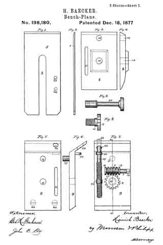
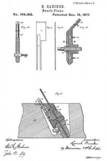
In the accompanying drawings, illustrating my invention, in which like reference-characters indicate the same parts, Figure 1 is a plan view, and Fig. 2 an edge view, of the plane iron or bit; Fig. 3 is a plan view, and Fig. 4 an edge view, of the upper break-iron. Fig. 5 is a plan view, and Fig. 6 an edge view, of the under break-iron, with the adjusting mechanisms attached; Fig. 7, a view of the clamping mechanism. Fig. 8 shows the clamping-screw, and Fig. 9 an operating-key. Fig. 10 shows an adjusting-screw. Fig. 11 is a vertical section of all the parts fitted together in operative position. Fig. 12 is a plan view, and Fig. 13 an edge view, of a rabbet-plane iron, and Fig. 14 is a modification of the mode of fastening the iron or bit in place.
The steel iron or bit 5 is composed of a thin sheet of steel, of even thickness, which is sharpened at its bottom edge, and it is provided with a slot, 2, extending centrally from its top edge to a distance beyond its middle part. It is adjusted in the plane-stock between two break-irons, 8 9, one of which (the lower, 9) is secured to the plane-stock. The iron or bit lies between these break-irons, as in Fig. 11, and the said devices are fastened securely together by means of a clamping-screw, 10, whose stem passes through a hole, 11, in the under break-iron 9, through the slot 2 in the iron or bit, and enters a screw-threaded hole, 12, tapped into the upper break-iron 8. When the iron or bit is properly adjusted between these break-irons, it may be firmly secured by properly tightening said clamping-screw. The upper break-iron 8 and the plane iron or bit are prevented from moving laterally with respect to the under break-iron 9 by means of a pin, 13, projecting from the inner face of the under break-iron 9, passing through the slot 2 of the iron or bit, and entering a hole, 14, in the upper break-iron 8. The parts thus held together are secured in the mortise in the plane-stock 15 by means of an arm, 16, projecting rearward from the under break-iron, and fastened to the stock 15 by means of a screw. The lower end of the under break-iron rests upon one side of the mortise, where it is secured by screws 40, while the front surface of the end of the upper break-iron rests upon the other side of said mortise, the devices being thus held steadily in place.
In order that the iron or bit 5 may be adjusted while its break-irons are hired in the mortise in the plane-stock, the head 6 of the clamping-screw is provided with gear-teeth, fitting a worm, 4, the shank 7 of which turns in arms 17 18 projecting from the rear face of the under break-iron 9. The shank 7 of this worm is provided with a squared head, 19, which fits a similar socket in a turning-key, 20.
By these devices the said clamping-screw 10 may be turned in and out of the screw-threaded hole 12 by inserting the key 20 through a hole (not shown) in the side of the plane-stock, engaging the same with the head 19 and operating said key in the proper direction.
In order to adjust the plane-iron vertically with respect to the break-irons and plane-stock, and thus protrude its cutting-edge the desired distance, each of the break -irons is provided with slots in which a pin connected with said plane-iron may freely play. The slot in the upper break-iron is marked 21, and that in the lower break-iron is marked 22. The pin 23, operating the iron 5, projects from a hub, 24, and enters one of two holes, 25 26, with which said plane-iron is provided. An ad-
justing-screw, 27 , having a screw-threaded shank, which runs in a threaded hole tapped through the hub 24, is supported in a collar, 30, fast to the underbreak-iron, and its squared head (adapted to fit the socket of the turning-key 20) projects above the plane-stock. This construction permits the rotation of said screw 27 to raise or lower the hub 24, and to impart a like movement to the plane-iron without disturbing the break-irons.
It is evident that in order to adjust the plane-iron in either direction the clamping-screw 10 must be first loosened, whereupon the adjusting movement may be imparted by means of the adjusting-screw 27. This done, the iron may be again secured by operating the clamping-screw 10.
Furthermore, if it is desired to remove the plane-iron it may be done when the break-irons are adjusted so as not to clamp and hold the said iron.
In the modification , Figs. 12, 13, 14, which represent the irons of a rabbet-plane, the devices are constructed substantially as before described, except that the adjusting-screw 27 is omitted, and the clamping-screw is adapted by means of a squared head to be operated by means of the turning-key, which operation may be the more readily effected by having the head of said screw project from the front side of the upper break-iron, the under break-iron, in this instance, being provided with the screw-threaded hole 12.
What is claimed is —
1. The combination of the plane iron or bit 5, upper and under break-irons 8 9, and clamping-screw 10, substantially as described.
2. The combination of the plane iron or bit 5, upper break-iron 8, having hole 14, under break-iron 9, having projecting pin 13, and clamping-screw 10, substantially as described.
3. The combination of the plane iron or bit 5, break-irons 8 9, clamping-screw 10, worm 4, and geared head 6, substantially as described.
4. The combination of the break-irons 8 9, having slots 21 22, with the plane iron or bit 5, having a slot, 2, pin 23, and adjusting-screw 27, substantially as described.
5. An improved plane, consisting of a bit having an equal thickness throughout its length, and a slot, 2, break-irons 8 9, clamping-screw 10, and an adjusting mechanism, as screw 27 and pin 23, substantially as described.
In testimony whereof I have signed my name to this specification in the presence of two subscribing witnesses.
HEINRICH BAECKER.
Witnesses:
BERNH. SCHENK,
FRANZ MAYENBARN.


