No. 1,092,326 – Fastening For Plane-Bits (John Bahmiller) (1914)
[paiddownloads id=”695″]1092326


UNITED STATES PATENT OFFICE.

_________________

JOHN BAHMILLER, OF SALEM, OHIO.

FASTENING FOR PLANE-BITS.

_________________

1,092,326. Specification of Letters Patent. Patented Apr. 7, 1914.
Application filed November 25, 1912. Serial No. 733,449.

_________________

To all whom it may concern:

Be it known that I, JOHN BAHMILLER, a citizen of the United States, residing at Salem, in the county of Columbiana and State of Ohio, have invented certain new and useful Improvements in Fastenings for Plane-Bits, of which the following is a specification, reference being had to the accompanying drawings.

This invention relates to new and useful improvements in fastenings for plane-bits and has for its object to provide a fastening which will admit of the bit being readily adjusted to the various positions desired.

A further object of the invention resides in providing a bit having a central longitudinal slot, the one wall of which is provided with rack teeth and a still further object resides in providing means on the securing member between the bit and cap-iron adapted for cooperation with said rack teeth to adjust said bit to its various positions.

A further object of the invention resides in providing a device which is extremely simple and durable in construction, inexpensive to manufacture and one which will be very eflicient and useful in operation.

With these and other objects in view, the invention consists in the novel features of construction, combination and arrangement of parts as will be hereinafter referred to and more particularly pointed out in the specification and claim.

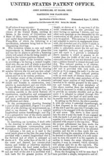
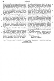
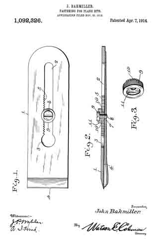
In the accompanying drawing forming a part of this application, Figure 1 is a plan view of a bit showing my improvements applied to use thereon. Fig. 2 is a vertical longitudinal section therethrough; and Fig. 3 is a perspective view of the sleeve member adapted to cooperate with the rack teeth on the bit.

In describing my invention, I shall refer to the drawing in which similar reference characters designate corresponding parts throughout the several views and in which —

1 indicates a bit such as is used in the usual bench plane or the like, the same being provided with a central longitudinal slot 2, the forward end of which is enlarged as shown at 3. The under face of the bit 1, at the outer end thereof, has counter-sunk therein and welded or otherwise similarly secured thereto, the hard metal surface 4, which extends to the cutting edge thereof and one wall of the slot 2 is provided with rack teeth for the greater portion of its length, as shown at 5. A cap-iron 6 of the usual construction, is also provided, the same having an opening 7 therein, and any other such openings as are demanded by the construction of the plane to which the same is to he applied. This opening 7 is threaded and adapted to receive in engagement therewith, the threaded end of a screw 8 which is extended through the slot 2 of the bit 1. In order to adjustably secure the bit and cap-iron together, however, and properly support the screw 8, I provide a substantial sleeve member 9, which is greater in diameter than the width of the slot 2 and is externally reduced at one end thereof to permit a portion thereof to extend through said slot. This reduced portion is of substantially the same diameter as the width of said slot and is provided with rack teeth, as shown at 10, to engage the teeth 5 in the one wall of said slot. This reduced portion with its rack teeth 10 thereon forms a substantial gear and the outer periphery of the enlarged upper portion of said member 9 is knurled to be readily grasped by the operator and turned. The inner periphery of this sleeve member from the enlarged end thereof, is increased in width as shown at 11 to provide an annular shoulder and as the screw 8 is adapted to extend through this sleeve member, the head of said screw may be readily seated on this annular shoulder.

In setting up the device, the sleeve member 9, with the screw 8 extended therethrough, is first disposed in the enlarged portion 3 of the slot 2 and the cap-iron 6 brought into position to be engaged with the threaded end of said screw. The sleeve is then moved into the slot 2 until the teeth 10 are engaged with the teeth 5 of said slot, whereupon said member 9 is rotated until the bit is properly adjusted with respect to the cap-iron. When the proper adjustment has been made, the screw 8 is then turned until the same securely clamps said member 9 in its adjusted position and the bit is then ready for use. Should, during the operation of the plane, it be desired to adjust said bit, it is only necessary to turn the screw 8 in the opposite direction to loosen the same, whereupon the member 9 may be rotated, which operation will adjust said bit on the cap-iron. The screw is then tightened to securely retain the bit in the desired position.

From the foregoing it will be seen that I have provided a simple, inexpensive and efficient means for carrying out the objects of the invention, and while I have particularly described the elements best adapted to perform the functions set forth, it is obvious that various changes in form, proportion and in the minor details of construction may be resorted to without departing from the spirit or sacrificing any of the principles of the invention.

The hard metal surface 4 which is counter-sunk in the under face of the bit 1, and extends to the cutting edge thereof, is a plate which will prevent the cutting edge from being unnecessarily nicked during the use of the device and thereby obviate the necessity of constantly sharpening the same, The provision of such a plate on the bit will not materially add to the cost thereof and in the end will save considerable time and expense.

Having thus described this invention, what I claim is:–

In a plane, the combination with a cap iron having a threaded opening arranged about centrally therein; of a bit provided with a longitudinal slot terminating in an enlargement at one end thereof, one wall of said slot being provided with teeth extending for the greater portion of its length, a sleeve disposed in the slot of said bit having teeth formed on the outer periphery thereof, in engagement with the teeth of the one vvall of said slot, the teeth on said sleeve also contacting lightly with the opposite wall of said slot to prevent a loose movement of the sleeve therein, a disk-like head member formed on the upper end of said sleeve to project on opposite sides of the slot in said bit and rest on the top face of the latter, said head member being of less diameter than the diameter of the enlargement of said slot and provided with a socket in the top face thereof, means provided on the outer peripheral edge of the head member, whereby to readily grasp the same, and a headed screw disposed through said sleeve and engaged at its lower end with the threaded opening of said cap iron, the head of said screw being received snugly in the socket of the head of said sleeve to bind tightly therein and retain the bit in any adjusted position with respect to the cap iron.

In testimony whereof I hereunto affix my signature in the presence of two witnesses.

JOHN BAHMILLER.

Witnesses:
K. L. COBOURN,
MYRTA L. COBOURN.

_________________

Copies of this patent may be obtained for five cents each, by addressing the “Commissioner of Patents, Washington, D. C.”
_________________

No. 748,199 – Matching-Plane (Alexander Mason) (1903)

[paiddownloads id=”595″]748199


UNITED STATES PATENT OFFICE.

_________________

ALEXANDER MASON, OF SALEM, MASSACHUSETTS.

MATCHING-PLANE.

_________________

SPECIFICATION forming part of Letters Patent No. 748,199, dated December 29, 1903.
Application filed March 20, 1903. Serial No. 148,745. (No model.)

_________________

To all whom it may concern:

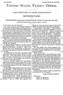
Be it known that I, ALEXANDER MASON, a citizen of the United States, residing at Salem, in the county of Essex and State of Massachusetts, have invented certain new and useful Improvements in Matching-Planes; and I do hereby declare the following to be a full, clear, and exact description of the invention, such as will enable others skilled in the art to which it appertains to make and use the same.

This invention relates to matching-planes; and it consists in the novel construction and combination of the parts hereinafter fully described and claimed.

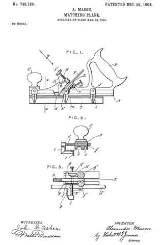
In the drawings, Figure 1 is a side view of the matching-plane. Fig. 2 is a cross-section taken on the line x x in Fig. 1. Fig. 3 is a partial plan view showing the clamping-levers and looking in the direction of the arrow y in Fig. 1.

A is the body of the plane, provided with a handle B at one end and a knob C at the other end. The body portion A has a broad groove b and a narrow groove c in its under side, and D is a longitudinal rib on the upper side of the body portion.

E is an inclined support for the blades, which also projects on the upper side of the body portion, and d represents slots or notches in the body portion A for the blades to project through.

F is a single cutting-blade, and G is a forked cutting-blade. These blades are laid upon the support E, one on each side of the rib D, and are clamped in position by means of two clamping-levers f and g, which are pivoted on the end portions of a pin H, which is secured in the rib D. These clamping-levers are provided at their upper ends with thumb-screws f’ and g’, which bear against the blades, so that the lower ends of the levers clamp the said blades securely in position.

I is a guide for the plane. This guide is provided with projecting brackets i at its end and middle portions. The end brackets carry bars J, which are slidable in guide-holes j in the body of the plane. The middle bracket carries a bar K, which is slidable in a hole k in the body of the plane and which is provided with a series of cross-holes m.

M is a spring-pressed stop-pin which is slidable in a lug n on the body of the plane and which engages with the said cross-holes. The guide is slid so as to suit the work, and it is then secured in position by means of the said stop-pin.

The two blades form three separate cutters, and they will tongue and groove boards of widely-varying thickness in a very satisfactory manner.

What I claim is —

In a matching-plane, the combination, with a body portion, of a guide for the said body portion provided with projecting brackets at its middle and end portions, bars projecting from the said end brackets and slidable in cross-holes in the said body portion, a bar projecting from the middle bracket and provided with a series of cross-holes and slidable in a hole in the said body portion, and a spring-actuated stop-pin carried by the said body portion and engaging with the cross-holes of the said bar.

In testimony whereof I affix my signature in presence of two witnesses.

ALEXANDER MASON.

Witnesses:
ALICE J. MURRAY,
FRED. K. DAGGETT.

No. 109,037 – Improvement In Planes (Ellis H. Morris) (1870)

[paiddownloads id=”174″]109037


United States Patent Office.


ELLIS H. MORRIS, OF SALEM, OHIO.

Letters Patent No. 109,037, dated November 8, 1870.
_________________

IMPROVEMENT IN PLANES.

_________________

The Schedule referred to in these Letters Patent and making part of the same.

_________________

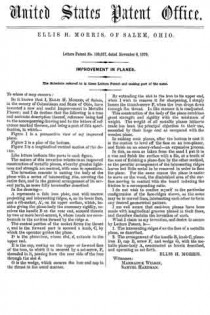
To whom it may concern:

Be it known that I, ELLIS H. MORRIS, of Salem, in the county of Columbiana and State of Ohio, have invented a new and useful Improvement in Metallic Planes; and I do declare that the following is a true and accurate description thereof, reference being had to thc accompanying drawing and to the letters of reference marked thereon, and being a part of this specification, in which —

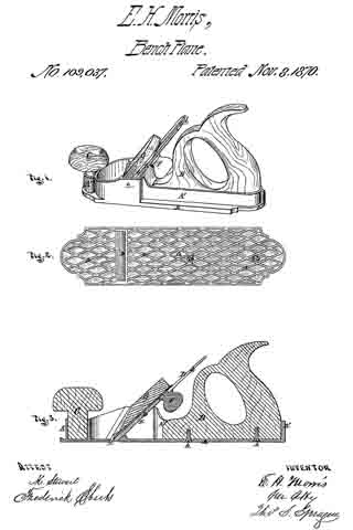
Figure 1 is a perspective view of my improved plane.
Figure 2 is a plan of the bottom.
Figure 3 is a longitudinal vertical section of the device.

Like letters indicate like parts in each figure.

The nature of this invention relates to an improved construction of metallic planes, whereby greater lightness and strength are secured, with case in operation.

The invention consists in casting the body of the plane with a series of intersecting ribs, covering the entire face, and in the general arrangement of its several parts, as more fuily hereinafter described.

In the drawing —

A represents a thin iron plate, cast with narrow projecting and intersecting ridges, a, on its lower face, and a rib-socket, A’, on its upper surface, which, besides giving the plane-body the necessary rigidity, receives thc handle B at the rear end, secured therein by two or more bevel-screws, b, whose heads are countersunk in the cavities formed by the ridge a.

The central portion of the socket forms the throat c, and in the forward part is secured a knob, C, by which the operator guides the plane.

D is the plane-iron, whose slot, d, extends to the upper end.

E is the cap, resting on the upper or forward face of the iron, to which it is secured by a set-screw, F, threaded in it, passing from the rear side of the iron through the slot d.

G is the wedge, which secures the iron and cap in the throat in the usual manner.

By extending the slot in the iron to its upper end, when I wish to remove it for sharpening, I simply loosen the thumb-screw F, when the iron drops down through the throat. In like manner it is readjusted.

This construction of the body of the plane combines great strength and rigidity with the minimum of weight. The weight of all metallic planes hitherto made has been the principal objection to their use, seconded by their large cost as compared with the wooden plane.

In making such planes, after the bottom is cast it is the custom to level off the face on an iron-planer, and finish on an emery-wheel — an expensive process.

In this, as soon as taken from the sand I put it in a vise and finish the surface with a file, at a tenth of the cost of finishing a plane-face by the other method, as the peculiar arrangement of the intersecting ridges leaves but little metal to be removed in order to face the plane. For the same reason the plane is easier to move on the wood, the diminished area ofthe surface moving in contact with the board reducing the friction in a corresponding ratio.

I do not wish to confine myself to the particular configuration of the face-ridges shown, as the same may be in curved lines, intersecting each other to term any desired geometrical pattern.

I am well aware that cast-iron planes have been made with longitudinal grooves planed in their faces, and therefore disclaim the invention of such.

What I claim as my invention, and desire to secure by Letters Patent, is —

1. The intersecting ridges d on the face of a metallic plane, as described.

2. The arrangement of the handle B, knob C, plane-iron D, cap E, screw F, and wedge G, with the metallic plane-body A, constructed as herein described, and operating as set forth.

ELLIS H. MORRIS.

Witnesses:
MARMADUK WILSON,
SAMUEL HARDMAN.