No. 355,031 – Bench-Plane (Samuel D. Sargent) (1886)
[paiddownloads id=”418″]355031


UNITED STATES PATENT OFFICE.

_________________

SAMUEL D. SARGENT, OF NEW BRITAIN, CONNECTICUT, ASSIGNOR TO
THE STANLEY RULE AND LEVEL COMPANY, OF SAME PLACE.

BENCH-PLANE.

_________________

SPECIFICATION forming part of Letters Patent No. 355,031, dated December 28, 1886.
Application filed September 6, 1886. Serial No. 212,803. (No model.)

_________________

To all whom it may concern:

Be it known that I, SAMUEL D. SARGENT, a citizen oi the United States, residing at New Britain, in the county of Hartford and State of Connecticut, have invented certain new and useful Improvements in Bench-Planes, of which the following is a specification.

My invention relates to improvements in bench-planes, and has particular relation to the manner of holding the cutting-bit within the stock.

One object of my improvement is to produce a plane in which the bit can be clamped by fewer and more direct motions, and therefore more conveniently, than heretofore.

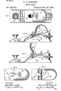
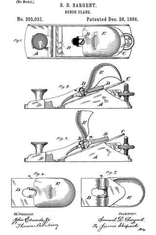
In the accompanying drawings, Figure 1 is a plan view of my plane. Fig. 2 is a side view of the same, partly in section and partly in elevation. Fig. 3 is a like view with the holding-cap placed in position with its lever raised ready for clamping the bit. Fig. 4. is a plan view of my holding-cap and its lever detached from the plane, and Fig. 5 is a like view of the reverse side of the same.

The stock A and the means for adjusting the cutting-bit after it is clamped within said stock may be of any ordinary construction.

B designates a headed screw set in a threaded hole in the frog or stock in the ordinary manner of this class of planes, so that by screwing it in or out the distance between the under side of the screw-head and the upper side of the cutting-bit C may be adjusted. A fixed stud with an adjustable head or a headed bolt adjusted by a nut would be the equivalent of this screw.

D is the holding cap or wedge, having a hole near its center, as viewed in plan view, which hole is large enough to let the head of the screw B pass through it. Pivoted to this cap by means of the pintle a is the clamping-lever E, the upper end of which is preferably of a form which will serve as a handle for the plane, while its lower and short end is slotted to take under the head of the screw upon two sides. The slot in this lever opens into the central hole in the cap. Said slot also extends both forward and backward of the pintle a, and hence said pintle is in two parts — one on each side of said slot — as indicated by the broken lines in Fig. 5.

The holding-cap is so formed on its under side as to bear upon the cutter only at the ends of said cap. After setting the bit in place the holding-cap and attached lever are placed on the bit (or on the cap-iron in case of a double plane-iron) by letting the central hole pass over the screw-head, then slipping the holding-cap downward to let the slotted end of the lever under the head of the screw, as shown in Fig. 3. The long end of the lever E is then depressed, when said lever fulcrums on the under side of the screw-head and carries the holding-cap downward into the position shown in Fig. 2, in which the pintle a (indicated by the broken circle) is slightly in advance of the lever on the screw-head, and consequently the pressure on the screw will hold the lever in its clamping position. If the adjusting-screw is properly set, the bit will be then firmly clamped. In putting in the clamping device the operator takes hold of the handle only and sets the holding-cap in place, then merely presses the outer end of the handle obliquely downward with only one motion. It will thus be seen that in clamping the bit the movement of the cap and lever-handle is practically in the same direction — forward and downward — and therefore these parts are more conveniently handled than parts which require to be moved in reverse directions — as, for instance, when the lever requires to be first moved backward and upward, as is the case in several prior planes. The clamping mechanism is also believed to be very efficient.

I claim as my invention —

In a plane, the combination of the holding-screw B, the holding-cap D, adapted to bear at each end upon the bit, and the clamping-lever pivoted or hinged to said cap between the bearing ends and having its upper face adapted to engage and fulcrum upon the under side of the screw-head, substantially as described, and for the purpose specified.

SAMUEL D. SARGENT.

Witnesses:
F. N. STANLEY,
W. J. WORAM.

No. 216,577 – Improvement In Flexible-Faced Plane-Stocks (Samuel D. Sargent) (1879)

[paiddownloads id=”303″]216577


UNITED STATES PATENT OFFICE.

_________________

SAMUEL D. SARGENT, OF NEW BRITAIN, CONNECTICUT, ASSIGNOR TO STANLEY RULE AND LEVEL COMPANY, OF SAME PLACE.

IMPROVEMENT IN FLEXIBLE-FACED PLANE-STOCKS.

_________________

Specification forming part of Letters Patent No. 216,577, dated June 17, 1879; application filed April 16, 1879.

_________________

To all whom it may concern:

Be it known that I, SAMUEL D. SARGENT, of New Britain, in the county of Hartford and State of Connecticut, have invented certain new and useful Improvements in Flexible Faced Plane-Stocks, of which the following is a specification.

My invention consists of the combination, in a flexible-faced plane-stock, of the body of the stock, having a transverse recess adjacent to the throat, with an independent throat-piece fitted to said recess and having the flexible face attached, as hereinafter described; also, in the throat-piece, of malleable metal, independent or otherwise, and provided with a series of lugs rigidly formed in one and the same piece with the throat-piece, in combination with the flexible face-plate having a series of holes through which said lugs pass, as hereinafter described.

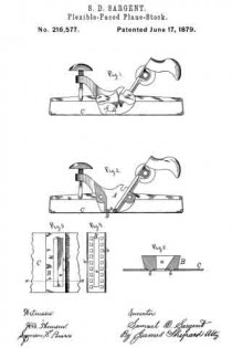
In the accompanying drawings, Figure 1 is a side elevation of a flexible-faced plane-stock which embodies my invention. Fig. 2 is alongitudinal section of the same through one side of the stock. Fig. 3 is a detached portion of the flexible-faced plate and attached throat-piece of the same. Fig. 4 is a detached under-side view of said throat-piece, and Fig. 5 is an enlarged sectional view on line x x of Fig. 3.

The flexible-faced stock, the mechanism for adjusting said face-plate, and the mechanism for adjusting the plane-iron are, with the exception of the parts hereinafter described, substantially the same as shown in the two patents to H. M. Clark, September 25, 1877; but they may be of any other style or kind.

The body of the stock A, I make of iron and with a dovetailed groove transversely across the bottom at the point where the throat a is designed to be located.

A dovetailed throat-piece, B, is fitted snugly into said groove, as shown in Figs. 1 and 2. This throat-piece has the ordinary throat a formed in it, through which throat the cutting-bit or plane-iron extends.

The flexible face-plate C is firmly secured to said throat-piece before it is inserted in the stock.

Heretofore, so far as I know, the flexible face-plates of circular plane-stocks have been secured directly and permanently to the stock, and generally by screws the heads of which were ground or polished off so as to take out the slot therein. A face-plate so secured could not be removed for repairs by an ordinary carpenter, and in any event could only be removed with more or less difficulty.

I intend to have the stocks and throat-pieces made by machinery and all alike, so that in case it is desired to remove the flexible face-plate and replace it with a new one it is only necessary to disconnect the ends of the face-plate and drive out the throat-piece.

A new face-plate can be ordered from the factory and inserted in its place, all of which can be done by any ordinary carpenter or mechanic, and without returning the plane-stock to the factory.

Thus it will be seen that the throat-piece and its attached face-plate are both attachable and detachable from the stock, whereby I call the throat-piece an independent one.

So far as the above feature of my invention goes the face-plate may be secured to the independent throat-piece by screws, rivets, or in other ordinary manner; but I prefer the method hereinafter described, and which constitutes the second feature of my invention.

I make the throat-piece of some kind of malleable metal, (good malleable iron will answer,)
and with a series of lugs, b, upon its under side. A mill is then run over the surface of the throat-piece both lengthwise and crosswise, to mill the entire surface, except that occupied by the lugs, leaving them square, as shown in Fig. 4.

A series of holes of corresponding shape and location are punched in the face-plate, which holes are conntersunk on the face side of the plate by a proper revolving tool. The lugs of the throat-piece are then driven into the holes in the plate, their ends upset or riveted, and then polished off, when the plate is ready for use.

The under face of the throat-piece outside of the lugs may be slightly rounded, and said piece may be made so thick that the face-plate will project slightly below the other parts of the stock, so that a good convex curve may be given to the face of said plate.

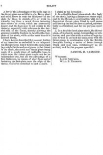
A few of the advantages of the solid lugs on the throat-piece are as follows, viz: Being short and solid, there is only the thickness of the plate for them to stretch, give, or work in, whereby they form a much firmer fastening than screws or rivets, which are necessarily longer, and the lugs may be set nearer to the throat a, especially with reference to the beveled side of the throat, thereby allowing the greatest possible freedom in bending the face-plate of the stock, while at the same time it is secured firmly.

I have herein described this second feature of my invention as embodied in an independent throat-piece; but if desired the same rigid lugs might be formed contiguous to the throat in the stock, the stock and throat-piece being made of a single piece of malleable iron, in which case the throat-piece would not be an independent one, but all the advantage of a firm fastening, by reason of short lugs and of fastening the face-plate near the edge of the throat, would be embodied in such a stock.

I claim as my invention —

1. In a flexible-faced plane-stock, the body of the stock, having a transverse recess adjacent to the throat, in combination with an independent throat-piece itted to said recess and having the flexible face attached, substantially as described, and for the purpose specified.

2. In a flexible-faced plane-stock, the throat-piece, of malleable metal, independent or otherwise, and provided with a series of lugs rigidly formed in one and the same piece with the throat-piece, in combination with the flexible face-plate having a series of holes through which said lugs pass, substantially as described, and fbr the purpose specified.

SAMUEL D. SARGENT.

Witnesses:
JAMES SHEPARD,
WILL. B. THOMSON.

No. 192,132 – Improvement In Bench-Planes (Samuel D. Sargent) (1877)

[paiddownloads id=”279″]192132


UNITED STATES PATENT OFFICE.

_________________

SAMUEL D. SARGENT, OF NEW BRITAIN, CONNECTICUT, ASSIGNOR TO THE STANLEY RULE AND LEVEL COMPANY, OF SAME PLACE.

IMPROVEMENT IN BENCH-PLANES.

_________________

Specification forming part of Letters Patent No. 192,132, dated June 19, 1877; application filed November 4, 1876.

_________________

To all whom it may concern:

Be it known that I, SAMUEL D. SARGENT, of New Britain, in the county of Hartford and State of Connecticut, have invented certain new and useful Improvements in Bench-Planes, of which the following is a specification:

My invention consists, in a device for adjusting plane-bits, of a link constructed to operate in the manner hereinafter shown and described.

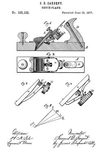
In the accompanying drawing, Figure 1 is a longitudinal section of a bench-plane which embodies my invention. Fig. 2 is a plan view of the same with the cap and plane-irons removed. Figs. 3 and 4 are side elevations, showing diifcrent modifications of the adjusting mechanism for said plane; and Fig. 5 is a diagram to aid in the explanation of my invention.

A designates the stock, and B the handle, both of which may be of any ordinary form and of any suitable material.

The object of my invention is to provide cheap, simple, and eflicient means for adjusting the cutting-bit in its proper position within the stock.
C designates the bit, which may be either a single or double iron, as may be desired. Upon the under side of said bit a series of alternate ribs and channels are formed, as shown in Fig. 1. Upon the under side of the frog a, which frog is the bed upon which the plane iron or bit rests, there is a screw, b, which, in Fig. 1, is a fixed stud threaded externally, and upon it is a larger screw, c, threaded internally to fit the screw b, and externally to fit the nut d, which it carries, the external. thread of the screw c being one banded, and its internal thread and thread of the screw b being threaded in the reverse direction. The larger screw c is also provided with a suitable head, D, or operating-handle.

To the nut d of the screw c one end of a link, e, is secured, and its opposite end lies loosely in a longitudinal slot formed in the frog a, as shown in Fig. 2. This lower end of the link e has a thin projection, which projects a little above the face of the frog, and engages in one of the grooves or channels formed in the under side of the bit, and it is necessary that the link at this end shall rest on ways or other support, so that said end cannot disengage from the plane-bit. The link between its two ends must be clear of all bearings, so as to allow of its free movement. The ordinary holding-cap E, or other proper means, holds the bit in place.

By turning the screw c in one direction the nut d is forced toward the frog a, carrying with it that end of the link e, and, as said link cannot change its length, it follows that the lower end, which is engaged with the cutting-bit, must move downward in the slot in the frog a, and, being so engaged. it must also force the cutting-bit downward with it. By turning the screw in the opposite direction the bit is drawn upward.

The link, for convenience’ sake, is made crooked; but its operation is the same, so long as it is sufficiently rigid, as if it was formed on a straight line between its ends — that is, from the point at which it is secured to the nut to its projecting point at the time of the frog. The operation of this link is, perhaps, more clearly illustrated by reference to the diagram, Fig. 5. The screw, the frog, and the link together form a triangle. In Fig. 5 the side J K is the base of the triangle, and represents the axial line of the screw; the side J 1 the perpendicular, and represents the face line of
the frog, and the side K 1 the hypotenuse, and represents the axial line of the link.

ln the adjustment of the plane iron with this triangular mechanism the link or hypotenuse of the triangle is made to change its position; but it is so confined that its two ends will always be one on the base-line, and the other on the perpendicular-Iine, of a triangle. Three different positions of the link are represented in Fig. 5 — the first by the solid line K 1, the second by the broken line L 2, and the third by the dotted line M 3 — by which it will be seen that, as one end of the hypotenuse is changed in such direction as to shorten the base, the vertex of the vertical angle is carried away from the base. In the diagram the vertex of the vertical angle is changed about one-eighth of an inch for every change there represented. A link engaging with a plane-bit, and changing its position in like manner, would move said bit one-eighth of an inch for every such change.

In Fig. 1 there is a compound screw, hereinbefore described. Its object is to get all the advantage of a fine-threaded screw and the speed of a coarse-threaded one. Such compound screw moves the nut fd just twice as far as it would be moved by it single screw having the same number of threads to an inch, whereby a less number of revolutions of the screw are required in order to effect the desired adjustment than with a single screw.

In Fig. 3 a single screw, F, is shown; but the link and nut are the same as those shown in Fig. 1. The screw is also set at an oblique angle to the face of the frog, in which position the movement of the nut endwise on the screw gives a greater range of motion to the lower end of the link than it would otherwise have.

In Fig. 4 two links, f g, are employed, and jointed together at their meeting ends. The link g is confined to the frog at one end to prevent longitudinal movement. An arm or extension at one end of the link f rests in at grooved nut, h, working on the screw G, and the opposite end of said link f plays loosely in a slot in the frog, as before described for the link e, the object of the additional link g in said rnodification being merely to give a little more throw to the adjustment.

In all of the modifications and mechanisms herein described the link e is employed and arranged to operate substantially the same.

I claim as my invention —

In a device for adjusting plane-bits, the link e, constructed to operate substantially as shown and described, for the purpose set forth.

SAMUEL D. SARGENT.

Witnesses:
FRED. N. STANLEY,
T. A. CONKLIN.