
No. 299,927 – Plane (Samuel E. Hilles) (1884)
UNITED STATES PATENT OFFICE.
_________________
SAMUEL E. HILLES, OF CINCINNATI, OHIO.
PLANE.
_________________
SPECIFICATION forming part of Letters Patent No. 299,927, dated June 3, 1884.
Application filed March 19, 1884. (No model.)
_________________
To all whom it may concern:
Be it known that I, SAMUEL E. HILLES, a citizen of the United States, and a resident of Cincinnati, in the county of Hamilton and State of Ohio, have invented certain new and useful Improvements in Planes, of which the following is a specification.
My invention relates to an improvement in planes.
The object of my invention is, first, to provide suitable attachments for holding the cutter or bit in position; second, to provide improved means for attaching both vertical and side guides to regulate the cutting of grooves, gains, or rabbets.
The invention consists in the novel construction and combination of devices hereinafter described and claimed, reference being had to the accompanying drawings, in which —
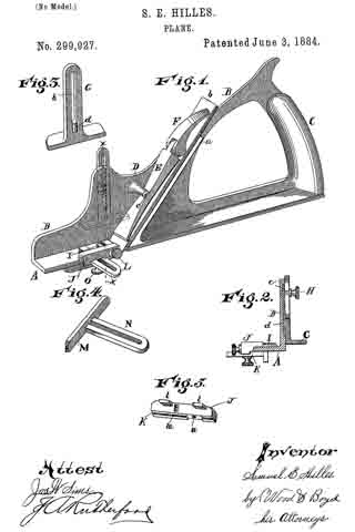
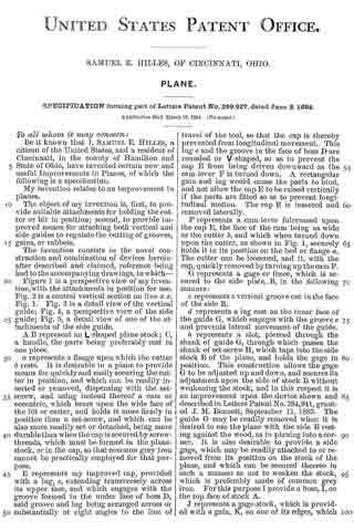
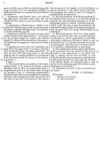
Figure 1 is a perspective view of my invention, with the attachments in position for use. Fig. 2 is a central vertical section on line x x, Fig. 1. Fig. 3 is a detail view of the vertical guide; Fig. 4, a perspective view of the side guide; Fig. 5, a detail view of one of the attachments of the side guide.
A B represent an L-shaped plane-stock; C, a handle, the parts being preferably cast in one piece.
a represents a flange upon which the cutter b rests. It is desirable in a plane to provide means for quickly and easily securing the cutter in position, and which can be readily inserted or removed, dispensing with the set-screw, and using instead thereof a cam or eccentric, which bears upon the wide face of the bit or cutter, and holds it more firmly in position than a set-screw, and which can be also more readily set or detached, being more durable than when the cap is secured by screw-threads, which must be formed in the plane-stock, or in the cap, so that common grey iron cannot be practically employed for that purpose.
E represents my improved cap, provided with a lug, e, extending transversely across its upper face, and which engages with the groove formed in the under face of boss D, said groove and lug being arranged across or substantially at right angles to the line of travel of the tool, so that the cap is thereby prevented from longitudinal movement. This lug e and the groove in the face of boss D are rounded or V-shaped, so as to prevent the cap E from being driven downward as the cam-lever F is turned down. A rectangular gain and lug would cause the parts to bind, and not allow the cap E to be raised vertically if the parts are fitted so as to prevent longitudinal motion. The cap E is inserted and removed laterally.
F represents a cam-lever fulcrumed upon the cap E, the face of the cam being as wide as the cutter b, and which when turned down upon the cutter, as shown in Fig. 1, securely holds it in its position on the bed or flange a. The cutter can be loosened, and it, with the cap, quickly removed by turning up the cam F.
G represents a gage or fence, which is secured to the side plate, B, in the following manner:
c represents a vertical groove cut in the face of the side B.
d represents a lug cast on the inner face of the guide G, which engages with the groove c and prevents lateral movement of the guide.
h, represents a slot, pierced through the shank of guide G, through which passes the shank of set-screw H, which taps into the side stock B of the plane, and holds the gage in position. This construction allows the gage G to be adjusted up and down, and secures its adjustment upon the side of stock B without weakening the stock, and in this respect it is an improvement upon the device shown and described in Letters Patent No. 284,941, granted J. M. Bennett, September 11, 1883. The guide G maybe readily removed when it is desired to use the plane with the side B resting against the wood, as in planing into a corner. It is also desirable to provide a side gage, which may be readily attached to or removed from its position on the stock of the plane, and which can be secured thereto in such a manner as not to weaken the stock, which is preferably made of common grey iron. For this purpose I provide a boss, I, on the top face of stock A.
J represents a gage-stock, which is provided with a gain, K, on one of its edges, which gain is of the same width as the side gage, M, so as to allow it to be retracted outward a sufficient distance to employ the full width of the cutter b.
l represents lugs formed upon one side of the gage-stock J, which rests upon the top surface of the stock A, and prevents it from rocking.
L represents a thumb-screw, which is inserted through the gage-stock J, and taps into the boss I, rigidly securing stock J in position to firmly hold the gage M.
n represents a transverse gain cut upon the under surface of the gage-stock J. It is made of the proper shape to receive the slotted shank N, which slides laterally in the gain n, for adjusting the gage M to any desired width of cut.
O represents a set-screw for attaching the gage M to the gage-stock J in such a manner as to adjust the gage, as before described. It will be seen that the gage-stock J and the gage M can be readily attached to or removed from the plane-stock by means of the attaching screw L.
I claim —
1. The combination, in a plane, of the right-angled stock A B, having the flange a, and attached lateral boss D, constructed with a longitudinal groove on its under side, the cap E, having a lug, e, extending transversely across its upper face, and adapted to be slipped sidewise into engagement with the groove of the boss to prevent movement of the cap in the direction of its length, and the swinging cam F, pivoted to the upper end of the cap, for clamping the cutter b upon the flange a substantiallty as described.
2. The combination, with the plane-stock A B, formed with a groove, c, in one side of the part B, but not extending through it, of the adjustable gage G, slotted vertically and provided with the lug d and the set-screw H passed through the slot of the gage and tapped into the part B of the stock, substantially as described.
3. The combination, With the right-angled stock A B, having the boss I on the top face of the part A, of the gage-stock J, provided with lugs l, resting on the face of stock A, and the thumb-nut L inserted through the stock J, and tapped into the boss I to secure stock J in position, substantially as described.
4. The combination of the right-angled stock A B, provided with the boss I on the face of the part A, the gage-stock J, provided with lugs l resting on the face of stock A and , formed with the transverse gain n, and secured to the stock by screw L, the gage M, formed with slotted shank N, entering gain n, and screw O for attaching gage M to stock J substantially as described.
In testimony whereof I have hereunto set my hand.
SAML. E. HILLES.
Witnesses:
ANDREW E. SCOTT,
A. GLUCHOWSKY.