
No. 453,524 – Bench-Plane (Saverio Tuoti) (1891)
UNITED STATES PATENT OFFICE.
_________________
SAVERIO TUOTI, OF NEW YORK, N. Y.
BENCH-PLANE.
_________________
SPECIFICATION forming part of Letters Patent No. 453,524, dated June 2, 1891.
Application filed August 7, 1888. Serial No. 282,165. (No model.)
_________________
To all whom it may concern:
Be it known that I, SAVERIO TUOTI, of the city, county, and State of New York, have invented a new and Improved Bench-Plane, of which the following is a full, clear, and exact description.
My invention relates to bench-planes for wood-workers’ use, and has for its object to provide a simple, easy-working, efficient, and durable plane of this character.
The invention consists in certain novel features of construction and combinations of parts of the plane, all as hereinafter described and claimed.
Reference is to be had to the accoinpanying drawings, forming a part of this specification, in which similar letters of reference indicate corresponding parts in all the figures.
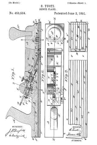
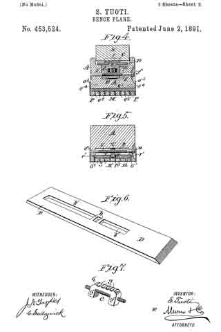
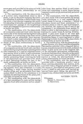
Figure 1 is a vertical longitudinal section of my improved bench-plane, taken on the line x x in Fig. 2. Fig. 2 is a plan view of the plane partly broken away and in section. Fig. 3 is a bottom face view of the plane partly broken away. Fig. 4 is a vertical transverse section of the plane, taken on the line y y in Fig. 1. Fig. 5 is a cross-section taken on the line z z in Fig. 1. Fig. 6 is a top perspective view of the plane iron or cutter, and Fig. 7 is a detail perspective view of the nut and part of the screw by which the cutter is adjusted endwise.
The plane-stock A is made with the usual top recess a, which opens to a throat or passage a’, up through which escape the shavings made by the cutter B, which rests on or at the inclined bottom face or wall of the recess.
In the plane-stock and at the lower inclined wall of the recess a there is formed a groove or recess to accommodate a screw C, which is fitted at its forward end in a metal step-bearing c, set into the stock, and at its rear part is reduced in diameter at two places c’ c2, which form journals which are fitted, respectively, to a split box or bearing D and a block E. The two halves or parts of the bearing D are screwed or otherwise fixed to the plane-stock, and the block E is also a nut, into which is fitted a transversely-ranging screw F, which is journaled to or in the plane-stock and cannot move endwise, and has a head or finger-piece f which is accommodated in a recess made in the side of the plane-stock and does not project beyond the stock, and thus does not interfere with the free working of the plane.
The nut E is provided with an upper lug e, which fits laterally within the slot b’ of the plane iron or bit B, and the nut is laterally slotted at e’, where the main adjusting-screw C passes through it, and whereby as the screw F is turned the nut E may be caused to move laterally either way in the plane-stock, and the nut-lug e will shift the back end of the plane-iron laterally to adjust the cutting-edge of the iron properly with relation to the working-face of the plane either before or after the iron has been adjusted endwise by the main screw C, working in a nut G, fitted on it, and as presently explained. It will be noticed that the bearing and nut D E, by fitting the reduced parts of the screw C, prevent endwise motion of the screw.
The nut G is preferably formed with pendent end lugs g’ g’, into which the screw C is fitted, and at its upper face the nut is provided with a series of transverse notches g, into which one or more transverse bars b, which cross the plane-iron slot b’, are adapted to enter when the plane-iron is adjusted in the stock.
The wedge H is provided at its lower face with a plate I, which is fixed to the wedge at one end and at its other or free end is adapted to bear on a cross-bar b of the plane-iron or on the adjusting-nut or on both the cross-bar and nut, and onto which the plate I, which is preferably elastic, may be forced by a screw J, fitted into the wedge and preferably into a metal nut j, set into it. The forward end or part of the wedge enters beneath a cross bar or rod K, fixed in the stock across its recess a, and the bar forms a fulcrum on which the wedge will rock when the screw J is tightened to cause its extrerne front end h’ to clamp the plane-iron down hard to the plane-stock very near the cutting-edge of the iron, and thus firmly hold it to prevent chattering of it when the plane is in use and assuring smooth clean work. The effect in this respect would be the same were the plate I dispensed with, in which case the screw J would bear directly on the plane-iron or on its adjusting-nut; but the plate I is preferably used, as it guards the plane-iron or its nut from injury by the end of the screw and assures a better clamping action of the wedge than would be afforded without it.
The screw C is provided at its rear end with a bevel-pinion c3, which meshes with a like pinion l3 on a short shaft l2, journaled in a bearing l’ on the plane-stock and provided with a head or finger-piece l, by turning which the screw C will be turned to shift the nut G for adjusting the plane-iron endwise for a finer or coarser cut, and which may be done without loosening the wedge-clamping screw. When the plane iron or cutter wears so it cannot be set farther ahead by operating the screw, the cross-bar b of the iron may be set into another front notch g after the nut is run back on the screw, this adjustment allowing all the tempered forward part of the iron to be used.
The plane-stock has the usual back and front handles A’ A2, andis also provided with a working-face of peculiar construction, the front part of which face is made adjustable backward or forward to narrow or broaden the shaving-throat a’ of the plane-stock, and as will next be described.
The larger section or portion M of the plane-face and its smaller adjustable section or portion N are made on the same general principle, or with a metal frame having strips of hard wood inserted in longitudinal grooves thereof. The face-section M is made with a cast-metal frame O, which has a broad cross-bar o behind the shaving-throat a’ of the plane-stock and beveled at the upper face to give substantial support to the plane-iron and to prevent undue wear of that part of the plane-face just behind the cutting-edge of the iron or at the back of the shaving-throat of the plane-stock, which usually wears quickly when made wholly or partly of wood. From each side of the cross-bar o there projects a forward ex-
tension o’ of the metal frame O, which form forward side parts m m of the main face-section M. These parts o’ o’ give support to the front sliding section N of the plane-face, as presently described, and at their front ends and above the section N they are connected and braced by a fIange-piece or bar m’, which is screwed to the front end of the plane-stock and really forms the front cross-bar or part of a flange o2, which projects upward all around the frame O and above its solid top plate o3 far enough to receive screws o4, which pass through the flange to hold the frame O and its front extensions o’ o’, or, in other words, the entire main plane-face section M m m, securely to the plane-stock.
Behind the metal cross-bar o and within the margin of the frame O said frame is provided with a series of longitudinally-ranging thin metal ribs or plates o5, which are cast on the back plate o3 of the frame and are set apart to provide spaces or form grooves between them, and into which are tightly fitted a series of hard-wood strips P, and the forward extensions o’ o’ of the frame O are also made hollow to accommodate like strips P, as most clearly shown in Figs. 3, 4, and 5 of the drawings.
The plane-face section N consists of a metal frame R, the inner face-plate r of which is provided with side tongues r’ r’, which enter grooves made in the opposite front side extensions m m of the main plane-face section M. On the plate r and between end lips or flanges r2 r2 of the frame R there is cast a series of lips or plates r3, set apart to provide between them a series of grooves or spaces, into which are tightly fitted a series of hard-wood strips S, like those P of the other face-section M.
In the forward end of the plane-stock and above its face-section N is provided a transverse slot or groove t, which accommodates a nut-block T, fitted to threads of a screw U, which is journaled in the plane-stock and traverses the recess t, and is provided at one end with a finger-piece or head u, which works in a recess at the side of the stock, so as to be out of the way in working the plane. The ends of the lower part of the nut T are inclined the same way horizontally, and are preferably rounded a little, so as to enter a diagonally-ranging slot V, which is formed at the inner face of the adjustable plane-face section N and preferably in the back of the metal frame R of said section. It is obvious that as the screw U is turned in one direction the nut T will slide in the plane-stock recess t, which guides it laterally, and also in the diagonal recess V’ of the movable plane-face section N, and will slide said section forward to open the throat a’ farther or make it broader, and that by turning the screw U in the other direction the face-section N will be moved backward nearer to the cutting-edge of the plane-iron to narrow the shaving-throat a’ of the plane, as the nature of the work to be done may require.
It will be seen that the plane-iron B sets at quite a sharp angle with the working-face of the plane. Consequently it will cut very easily, and this feature, combined with the simple and efiicient means provided for adjusting the plane-iron endwise and laterally, as hereinbefore explained, and the adjustability of the face-section N to regulate the size of the shaving-throat a’, insures true and smooth working of the plane on any quality or grade of lumber, whether it be soft or hard.
Having thus described my invention, what I claim as new, and desire to secure by Letters Patent, is —
1. The combination, with the plane-stock and its bit, of the longitudinal!y-extending screw having a bevel-gear on its outer end, a nut connecting the screw and the bit, and the transverse shaft l2, mounted on the stock under the upper end of the bit and having a bevel-gear at its inner end meshing with the screw-gear and provided at its outer end with an operating-handle, substantially as set forth.
2. The combination, with the plane-stock, of a cutter and a longitudinal screw in the stock, a nut on the screw engaging the cutter for adjusting it endwise, a transversely-ranging screw, a nut thereon engaging the cutter for adjusting it laterally, and said nut slotted transversely for passage of the longitudinal screw, all arranged for operation substantially as herein set forth.
3. The combination, with the plane-stock, of a composite metal and wood main face-section in rear of the throat and having front side extensions m m extending to the front end of the stock, and an adjustable front face-section fitted to slide longitudinally in said side extensions to regulate the size of the shaving-throat of the plane, substantially as herein set forth.
4. The combination, with the plane-stock, of a composite metal and wood main rear face-section having longitudinally-extending front side extensions m m, and an adjustable front face-section fitted to slide in said extensions, said main face-section provided with an upwardly-projecting flange receiving the body of the plane-stock and provided with screw or other fastenings holding the face to the stock, substantially as herein set forth.
5. The combination, with the plane-stock, of a face consisting of a main section M, having opposite front side extensions m m and comprising a metal frame having inserted wooden strips, and an adjustable front face-section fitted to slide in the extensions m to regulate the shaving-throat of the plane, substantially as herein set forth.
6. The combination, with the plane-stock, of a face consisting of a main section having opposite front side extensions and an adjustable front face-section fitted to said extensions and comprising a metal frame having inserted wooden strips, substantially as herein set forth.
7. The combination, with the plane-stock, of a face made with a main section M, having front extensions m m and consisting of a metal frame O, having a cross-bar o behind the plane-throat and front extensions o’ o’, division plates or ribs O5, and wood strips P, set between the plates or ribs O5 and in the extensions o’, an adjustable front section N, fitted to slide in the extensions m m and consisting of a metal frame R, having division-plates r3, and wood strips S, set next said plates, and said frame O having an upwardly-projecting flange o2, receiving screw or other fastenings to hold the face to the plane-stock, substantially as herein set forth.
8. The combination, with the plane-stock or guides thereon, of a front endwise-adjustable face-section provided with a diagonal slot or recess, a transverse screw in the stock, and a nut fitted to said screw and to the diagonal slot of the adjustable face-section, substantially as shown and described, whereby as the screw is turned said face-section will be shifted to narrow or widen the shaving-throat of the plane, substantially as herein set forth.
9. The combination, with the plane-stock provided with a transverse groove t and a front endwise-adjustable face-section, as N, provided with a diagonal groove or recess V, of a screw U, journaled at said groove t, and a nut T, fitted on said screw and having upper and lower parts fitting the grooves t V, respectively, substantially as herein set forth.
SAVERIO TUOTI.
Witnesses:
HENRY L. GOODWIN,
C. SEDGWICK.