No. 837,978 – Scraping-Tool (Justus A. Traut) (1906)

[paiddownloads id=”636″]837978


UNITED STATES PATENT OFFICE.

_________________

JUSTUS A. TRAUT, OF NEW BRITAIN, CONNECTICUT, ASSIGNOR TO STANLEY RULE &
LEVEL COMPANY, OF NEW BRITAIN, CONNECTICUT, A CORPORATION OF CONNECTICUT.

SCRAPING-TOOL.

_________________

837,978. Specification of Letters Patent. Patented Dec. 11, 1906.
Application filed May 26, 1906. Serial No. 318,811.

_________________

To all whom it may concern:

Be it known that I, JUSTUS A. TRAUT, a citizen of the United States, residing at New Britain, Hartford county, Connecticut, have invented certain new and useful Improvements in Scraping-Tools, of which the following is a full, cllear, and exact description.

My invention relates to improvements in woodworking-tools; and it consists in an improved scraper, the construction of which is such that it may be used, if desired, with an ordinary plane, merely substituting the same for the usual plane-iron. In this connection the device is capable of all of the adjustments to which the usual plane-iron is adapted and may be employed with an unusual degree of success.

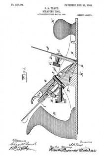
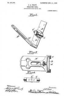
In the accompanying drawings, Figure 1 is a longitudinal section of an ordinary plane-body fitted with my improved scraper. Fig. 2 is a perspective view of the scraper and scraper frame or carrier. Fig. 3 is a plan view of the same. Fig. 4. is a detail view of a clamping member.

I will first describe the scraper and scraper-carrier.

A is the scraper-blade, having the usual sharpened edge.

B B’ are two arms of the frame or scraper-carrier arranged to carry the blade A. As shown, these arms B B’ are arranged in the form of a wedge or a V — that is, the outer bearing-surfaces of the same form a V. The plane-iron A is clamped against the outer bearing-surface of the arm B by means of any suitabie clamping device — for example, the member C, carrying the clamping-screw C’. The arm B’ is so constructed and arranged that it may be readily applied to the plane-iron support or “frog” of a plane, the connection being preferably such that the various adjusting devices commonly found on planes will be available for the purpose of adjusting the position of the cutting edge of the scraper-blade in the throat of the plane. In the drawings, Fig. 1, I have shown the scraper-frame as it would appear in place on an ordinary plane. In this view, D indicates the main body of the plane. E E’ are the handles. F is the usual frog on the plane-iron support. G is the usual clamping- plate cooperating with the screw-post J. H I are adjusting-levers such as commonly employed in planes and by which the plane-iron may be given any desired adjustment. These levers need not be explained in detail, since their operation is well understood.

On referring to Fig. 1 it will be seen that the scraper-frame is clamped to the frog precisely as the ordinary plane-iron is clamped thereon, and the edge of the scraper-blade A will project through the throat or passage in the sole of the plane in the same manner as will the edge of the plane-iron, excepting that it will stand at a substantially different angle. The arm B of the scraper-frame is cut back or recessed transversely near its lower end, as indicated at K, to give a clearance back of the cutting edge of the scraper-blade. This is done to permit the cutting edge of the scraper to yield slightly and is productive of the most effective results in operation. While the scraper-frame is primarily adapted for use in connection with the plane, nevertheless the frame or carrier will itself afford a convenient grip when the scraper is used independently of a plane-body. The angle of the bearing-surfaces of the arms B B’ (indicated in the drawings) is that best adapted for the most successful results when the scraper is to be used in connection with the plane; but this angle, of course, may be varied to some extent at will. In the arm B’ of the scraper-frame a central longitudinal passage B2 adords clearance for the post J.

L is the usual cam by which the clamping-plate G may be set down hard, so as to hold the scraper-frame firmly on its seat.

What I claim is —

1. As an article of manufacture, a scraper attachment for a plane, comprising a body having two arms inclined relatively to each other, a scraper-blade, means for adjustably securing the scraper-blade to one of said arms, the other arm having a longitudinal recess and a transverse recess above said longitudinal recess, said recesses being adapted to accommodate mechanism of a plane for effecting lateral and vertical adjustment respectively.

2. As an article of manufacture, a scraper attachment for a plane comprising, a body having two arms arranged at an angle relatively to each other and furnishing two bearing-surfaces, one for contact with the plane-support, the other for the reception of a scraper-blade, a scraper-blade, means for adjustably securing the same to the said bearing-face, said bearing-face at and near the meeting angle of the two arms being recessed to afford clearance for the blade adjacent to its cutting edge.

JUSTUS A. TRAUT.

Witnesses:
H. S. WALTER,
L. E. CLEMONS.

No. 755,587 – Scraping-Plane (William Ulses) (1904)

[paiddownloads id=”600″]755587


UNITED STATES PATENT OFFICE.

_________________

WILLIAM ULSES, OF LOS ANGELES, CALIFORNIA.

SCRAPlNG-PLANE.

_________________

SPECIFICATION forming part of Letters Patent No. 744,587, dated March 22, 1904.
Application filed October 29, 1903. Serial No. 179,070. (No model.)

_________________

To all whom it may concern:

Be it known that I, WILLIAM ULSES, a citizen of the United States, residing at Los Angeles, in the county of Los Angeles and State of California, have invented new and useful Improvements in Scraping-Planes, of which the following is a specification.

My invention relates to a plane for finishing surfaces made nearly smooth by the ordinary cutting-planes; and the object thereof is to provide a tool by means of which planed surfaces may be readily finished and with less danger of roughing the surface than if an ordinary scraper were used.

I accomplish this object by the scraping-planes described herein and illustrated in the accompanying drawings, in which —

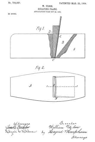
Figure 1 is a side elevation, with a portion in longitudinal central section taken on the line 1 1 of Fig. 2, of my scraping-plane. Fig. 2 is a view of the sole of my plane.

In the drawings, A is the stock, having a throat B for the reception of the plane-iron C and the binding-wedge D, which secures the plane-iron in the throat, binding it against abutments A’ on the sides of the throat. These abutments are shown in dotted lines in Fig. 1, the inner dotted line representing the top line of the abutments and the outer line representing the bottom line of the abutments. The tops of these abutments project forwardly of the bottoms, so that the top of the plane-iron is inclined forwardly, as shown in Fig. 1, when the wedge and iron are in place. I have found by practical test that an inclination of five-sixteenths of an inch in a stock of two inches in height produces very satisfactory results. The plane-iron is constructed, preferably, of a thin piece of tempered steel having the lower edges C’ thereof sharpened, as shown in Fig. 1, or otherwise formed into a scraping-surface. The front side of the binding-wedge forms the segment of a circle, and when the scraper-iron is secured in the stock it is bent into circular shape, as shown in Fig. 2, which causes the central portion thereof, by reason of the forward inclination of the top, to project through the stock a greater distance than the edges. With a scraper-iron two inches wide I have found that one-sixteenth of an inch produces a very satisfactory curvature and that a plane thus constructed will take out all the tool-marks and perfectly finish the surface. The curvature of the plane-iron caused by the wedge when in place in the stock prevents it from chattering. It will be observed that by this construction the central portion of the iron does its scraping in advance of the side portions, and thereby the danger of catching under the grain of the wood is lessened over that of using a scraper with a straight edge. It will also be observed that when the plane-iron is out of the stock its cutting edge is a perfect straight line and that it can thus be readily sharpened and that when put in place in the stock the edges follow at the rear of the center and are a little elevated above the center, thus preventing any marring of the surface upon which the plane is being used, the edges being preferably placed in the same plane as the sole of the stock.

Having described my invention, what I claim as new, and desire to secure by Letters Patent, is —

1. A scraping-plane comprising a stock having a throat with abutments on the sides and in the front portion thereof; a plane-iron composed of thin resilient metal and having its lower edges formed into a scraping-surface; a rigid binding-wedge of a length substantially equal to the height of the stock having a circular face adapted to pass into said throat back of the scraper-iron and bind said iron in said stock in a forwardly-projecting curved form.

2. A scraping-plane comprising a stock having a throat with abutments on the sides and in the front portion thereof, the tops of said abutments projecting forwardly of the bottom thereof; a plane-iron composed of thin resilient metal and having its lower edge formed into a scraping-surface; a rigid binding-wedge having a circular face adapted to pass into said throat back of the scraper-iron and bind said iron in place in the stock and to produce in said iron a forwardly-projecting curve.

ln witness that I claim the foregoing I have hereunto subscribed my name this 22d day of October, 1903.

WILLIAM ULSES.

Witnesses:
G. E. HARPHAM,
MARGARETÉ C. NICHOLSON.

No. 316,296 – Plane (Louis C. Rodier) (1885)

[paiddownloads id=”391″]316296


UNITED STATES PATENT OFFICE.

_________________

LOUIS C. RODIER, OF DETROIT, MICHIGAN.

PLANE.

_________________

SPECIFICATION forming part of Letters Patent No. 316,296, dated April 21, 1885.
Application filed November 8, 1884. (Model.)

_________________

To all whom it may concern:

Be it known that I, LOUIS C. RODIER, of Detroit, county of Wayne, State of Michigan, have invented a new and useful Improvement in Planes; and I do hereby declare the following to be a full, clear, and exact description of the same, such as will enable others skilled in the art to which it pertains to make and use it, reference being had to the accompanying drawings, which form a part of this specification.

My invention relates to bench-planes, and more particularly to metallic bench-planes, and has for its object, first, the combination, with a stock, of an improved knife holder or carriage provided with devices for operating the same and adjusting the knife to secure the desired depth of cut; second, the combination, with a stock, of a novel attachment for holding a toothing iron or scraper; third, to combine in a bench-plane the said knife-holder and said attachment for toothing irons and scrapers, said attachment being removable, so that the knife or bit may be removed and the toothing or scraper attachment be engaged with the stock,or said attachment be removed and the knife inserted, the plane being thus readily convertible for various uses; and, fourth, it consists in the general construction and arrangement of the novel devices, hereinafter described, and more particularly pointed out in the claims.

I carry out my invention as follows:

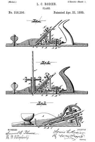
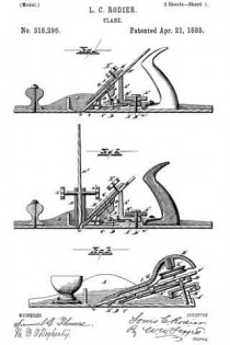
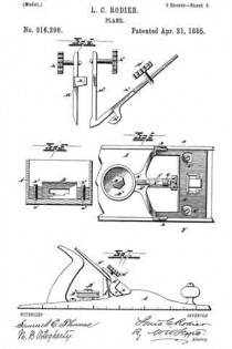
In the drawings, Figure 1 is a longitudinal section of a jack-plane, showing the knife-holder in position with the knife or bit in place. Fig. 2 is a similar section showing the toothing or scraper attachment in position. Fig. 3 is a modihcation adapting features of the device more particularly for a smoothing-plane or block-plane. Fig. 4. is a separate view of the toothing iron and scraper attachment. Fig. 5 is a cross-section along the line at x y, Fig. 6. Fig. 6 is a view showing the knife-carriage and its operating devices. Fig. 7 is a side elevation.

A represents the stock provided with a throat, a.

B is the knife-rest, which may be constructed of any suitable form or pattern, and adapted to hold the knife on a proper incline. It may be provided with ears b extending upward at the side of the knife, or these ears may be dispensed with, as shown in Fig. 3. This knife-rest is provided with a rearwardly-extending arm, b’, provided with a screw-orifice, b2, (shown in Fig. 1,) or otherwise adapted to receive the head of a screw, and to receive its force, as shown in Fig. 3. I also prefer to construct the knife-rest, when applied to jack-planes, with an extended knife-brace, b8. This knife-rest may be secured within the walls of the stock and suitably adjacent to the throat in any suitable manner, as sh own in Fig. 5. The knife-rest is screw-tapped to receive the screws b3 and b4 These screws are preferably constructed with rounded ends to engage in corresponding sockets, a’ and a2, in the base of the stock, the construction being such that the knife-rest may have a movable or slightly-vibratory movement, so that either side of said knife-rest may be elevated or depressed to more effectually adjust the knife to cut evenly across its entire edge.

C is a spring engaged with the knife-rest at one end, as shown at c, and under the arm b’
and upon a raised bed, A’, upon the base of the stock.

D is a bridging constructed preferably integral with the stock, under which the spring is extended, said bridging also preferably provided with a screw, d, adapted to bear upon the spring to give it greater tension upon the knife-rest. I do not limit myself to any special construction of this bridging.

The bed A’ is screw-tapped, as shown at a3, to receive a screw, B’.

B2 is a thumb-nut adapted to operate upon said screw, and to bear upon the rear of the arm b’ to tilt the knife-rest to any desired angle.

E is a knife-clamp provided with hooked arms e, adapted to engage over the ears b of the knife-rest, said ears being suitably cut away at their rear edge to receive said hooked arms, so that the one will be flush with the other, as shown in Fig. 7. The side walls of the stock are preferably cut away slightly to receive said ears and arms also, as shown also in Fig. 7.

E’ is a thumb-screw tapped into said clamp and adapted to tighten and hold the knife upon the knife-rest beneath. F is the knife. The clamp may have, however, any suitable engagement with the knife-rest.

When the thumb-nut B2 is forced down upon the arms b’ of the knife-rest, the effect will be to tilt the knife-rest and so adjust the knife relatively to the throat, said rest being adapted to have a slight longitudinal vibratory motion upon the ends of the screws b3 and b4, as well as a vibratory motion across the stock, while the pressure of the thumb-screw E clamps the lower part of the knife-clamp upon the knife near its cutting-edge, so that the knife is held firmly between said clamp and the knife-rest. The knife is thus readily held in position. The knife may be put in place by loosening the clamp, which is then raised to disengage its hooked arms from the ears of the knife-rest. When the knife is in place, the clamp is forced down so that its hooked arms shall be engaged over the ears of the knife-rest, and the thumb-screw may be tightened thereon when the cutting-edge of the knife has been properly adjusted.

As shown in Fig. 3, instead of providing the knife-rest with the screws b3 and b4, having rounded ends, forming the bearings of said rest, I may construct said rest with integral bearings or lugs b5, answering the same purpose as the screws in Fig. 5, the only difference being that the knife-rest cannot readily be adjusted across the stock as can be done, as already described, where the screws b3 and b4 are employed. So, also, instead of engaging the spring in the knife-rest, as shown in Figs. 1 and 2, the tension may be secured in essentially the same way by constructing the arm b with a cross-bar, as shown at b6, in which case the end of the spring may be engaged under the bridging, being passed over said cross-bar, as shown in Fig. 3, the tension being secured by means of the screw B’. By operating said screw the knife-rest may be tilted, as before, to secure the desired adjustment of the knife relative to the throat to make it cut more or less, as may desired.

To insure the proper location of the knife upon the rest and relatively to the throat, I also prefer to construct the knife with an orifice, f adapted to engage over a lug, G, which may be adjustably located beneath it either upon the spring, as shown in Fig. 3, or upon an arm, b7, integral with the knife-rest. This device when the lug is once adjusted properly will permit the ready engagement of the knife relatively to the throat, and when the knife becomes worn the lug can be adjusted to compensate for the wear.

H represents my improved toothing iron or scraper attachment, substantially as shown in Fig. 2, consisting of a suitable front clamp, H’, and rear clamp, H2, the front clamp being preferably provided with engaging-arms h, adapted to engage upon the rear clamp, said clamps provided with thumb-screws h and h2 to bind the toothing iron or scraper H3 between said clamps, as shown in Fig. 2. By means of the said screws the toothing-iron may be readily engaged in said clamps or removed thereupon for the insertion of the scraper, as desired, said clamps forming a holder or harness for the cutting-tool.

The rear clamp is provided with a wing, h3, constructed and arranged to be seated upon the knife-rest B. The knife-clamp E is then clamped upon the wing, the knife F being removed, which holds the said attachment firmly in place. It is evident that this attachment may be readily removed and the knife inserted, and vice versa.

Instead of engaging the wing h3 upon the knife-rest by means of the knife-clamp already described, the wing itself may be provided with engaging-shoulders h4, similar to the hooked arms e of said clamp, and serving a similar purpose.

I design to provide the stock of the plane with a scale-bar or measure, as shown in Fig. 7. The spring serves to take up any slack which may result in the adjustment of the knife-rest by means of the screw B’.

In the jack-plane, as shown in Figs. 1 and 2, the spring is engaged with the knife-rest forward of the bearings b3 and b4. In Fig. 3 the spring is engaged with the rest in the rear of the bearings, the spring operating simply in a reverse manner to take up the slack.

Instead of a screw, B’, a suitable cam may be employed. I would have it understood that I do not limit myself to the screw alone to secure this proper adjustment.

I do not limit myself to the definite and precise construction of the parts H’ and H2 of the attachment, as shown, nor providing the part H2 with a wing, h3, as they may be of any suitable construction to removably hold the toothing iron or scraper suitably in position in the stock.

What I claim is —

1. The combination of a plane-stock, a knife-rest provided near its lower end with a support which permits the rest to be tilted in the direction of the length of the stock and also transversely thereto, a spring to exert an upward pressure upon the rest, and means to regulate the longitudinal tilting of the rest, substantially as described.

2. The combination of a plane-stock, a knife-rest, screws passed through said rest near opposite sides thereof and bearing against said stock to permit the rest to be tilted in the direction of the length of the stock and transversely thereto, a spring to exert an upward pressure upon the rest, and means to regulate the longitudinal tilting of the rest, substantially as described.

3. The combination of a plane-stock, a knife-rest, screws passed through said rest near the opposite sides thereof and bearing against said stock to permit the rest to be tilted in the direction of the length of the stock and transversely thereto, a spring to exert an upward pressure upon the rest, means to regulate the tension of said spring, and a screw to regulate the longitudinal tilting of the rest, substantially as described.

4. The combination of the plane-stock, the knife-rest, a support under the rest, a lug, G, supported by and capable of sliding longitudinally on the support and adapted to engage and move with a knife, a knife-clamp above the rest, and a screw engaging a screw-socket in the clamp for holding the knife upon the rest, substantially as described.

5. The combination, with a metallic plane-stock, of a removable toothing iron or scraper composed of two clamps provided each with a clamping-screw, one of said clamps being provided with a wing to engage with a knife-rest on the stock, substantially as described.

6. The combination, with a plane-stock provided with a knife-rest and knife-clamp, of a removable toothing iron or scraper attachment consisting of front and rear clamps constructed and arranged to be engaged with each other and provided with clamping-screws, said rear clamp provided with a wing, h3, adapted to be engaged upon the knife-rest, the construction being such that said attachment may be removed and the knife be clamped upon the rest, and vice versa, substantially as described.

In testimony whereof I sign this specification in the presence of two witnesses.

LOUIS C. RODIER.

Witnesses:
N. S. WRIGHT,
W. B. O’DOGHERTY.

No. 315,014 – Bench-Plane (James Duncan) (1885)

[paiddownloads id=”389″]315014


UNITED STATES PATENT OFFICE.

_________________

JAMES DUNCAN, OF COSHOCTON, OHIO, ASSIGNOR TO HIMSELF,
WILLIAM W. BOSTWICK, AND FRANK C. HAY, ALL OF SAME PLACE.

BENCH-PLANE.

_________________

SPECIFICATION forming part of Letters Patent No. 315,014, dated April 7, 1885.
Application filed January 24, 1885. (No model.)

_________________

To all whom it may concern:

Be it known that I, JAMES DUNCAN, a citizen of the United States, residing at Coshocton, in the county of Coshocton and State of Ohio, have invented certain new and useful Improvements in Planes; and I do declare the following to be a full, clear, and exact description of the invention, such as will enable others skilled in the art to which it appertains to make and use the same, reference being had to the accompanying drawings, and to the letters and figures of reference marked thereon, which form a part of this specification.

This invention has for its object to improve the bench plane and scraper for which Letters Patent were granted to myself and Wm. H. Talbot, November 24, 1874, and numbered 157,162; and it consists in the construction and arrangement of the several parts, as hereinafter fully described and claimed.

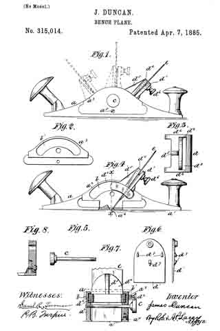
In the drawings, Figure 1 is a side elevation of the plane-stock, showing the outer face of the removable cheek and an adjustment of of the bit. Fig. 2 shows the inner face of the removable cheek. Fig. 3 shows the adjustable frame which carries the bit and bit-clamping plate. Fig. 4 is a side elevation of the plane-stock, having the cheek removed to show the inner face of the opposite or immovable cheek and the edge of the adjustable frame. Fig. 5 is the clamping-bolt, which passes through both cheeks and has its end threaded to fit the threaded opening in the immovable cheek. Fig. 6 shows-the outer face and an edge view of the bit-clamping plate. Fig. 7 is a vertical cross-section of the plane-stock on line x x, Fig. 4; and Fig. 8 is a detail view on an enlarged scale to show the joint between the movable cheek and the flange, the joint being exaggerated to show clearly the construction.

a is the plane-stock, composed of a-base-plate, a’, provided with suitable handles on its opposite ends, an im movable cheek, a2, and a movable cheek, a3. The plane-stock is so formed as to provide a flange, a4, set slightly in from the outer edge of the base-plate, and against which the lower edge of the movable cheek fits snugly. The flange and the movable cheek are jointed together, so as to bring the outer face of the cheek flush with the cuter edge of the base-plate, and the inner face thereof flush with the inner face of the flange. The plane-stock and the movable cheek are both so constructed and jointed by means of tenons and mortises that when brought together and a small retaining-screw, a5, inserted, as shown, the said cheek will be held in place. The joint between the movable cheek is so formed as to permit a slight movement — of the top of the cheek inward toward the plate d. This construction is shown in the enlarged detail view in Fig. 8. The cheek by this movement is more easily clamped against the plate d, and obviates the necessity of springing the cheek by the clamping-bolt. The slight beveling of the joining edges of the flange and cheek and the slight enlargement of the hole in the cheek through which the screw of passes permits a movement of the top of said cheek. of about one thirty-second part of an inch.

The plane-stock is provided with a transverse bit-opening or throat, a6, of common form, to permit the edge of the bit to project below the base-plate in all planes.

Guide-channels b b’ are formed in the inner faces of the cheeks. These channels are arcs of circles described on radii having their centers in the transverse throat a6, and have their ends arranged near the base-plate, as shown.
They extend on both sides of a vertical line, as x x, Fig. 4, drawn from the throat a6. This extension of the guides permits the shifting of the bit to either side of said line for purposes hereinafter explained.

c is the clamping-bolt, which passes through the cheek a3 and into a threaded opening in cheek a2, as shown.

d is the adjustable frame which carries the bit and the clamping-plate d’. The ends d2 d2 are curved to correspond with and are adapted to fit neatly into and slide easily in the guide-channels b b’. It is provided with a transverse bit-opening, d3, made wide enough to receive the bit and the clamping-plate d’. A bearing-plate, d4, is projected upward from the frame d, having its smooth face flush with the side of the opening d3, and arranged on a radial line having its center in the throat a6. This plate d4 is suitably braced on its back by a rib, d5. The bit e lies against the smooth face of the plate d4, and is held by a set-bolt, d6, threaded in the upper end of the clamping-plate d’, as shown.

The clamping-plate d’ has its face next the bit e made smooth, and on its back are provided a series of lugs, d7, so arranged that part of them will be on the upper side of and the others below the plate d. The clamping-plate is held from moving vertically by these lugs, and at the same time will have all the needed horizontal movement of its ends, whereby it is adjusted to the position of bit e. The adjustable frame is put in position in the bit-stock by removing the cheek a3 and placing the curved edges d2 in the guide-channels. The screw a5 holds the cheek a3 in place after the latter is put into position. The clamping-bolt c binds the jaws against the edges of the frame d, and holds the latter in any desired position.

In adjusting the plane the bit-plate d’ is first placed in the slot d3, and its lugs are properly engaged upon the frame. The bit is then inserted between the plates d’ and d4, and after being set properly is clamped in place by the set-bolt d6.

In this device the operation of setting the bit, whether for planing or scraping, is very much simplified. By slightly loosening the bolt c the frame d can be moved to give to the bit any desired set, inclined or vertical. By taking the bolt c out the frame d can be moved to throw the bit inclined toward the opposite end of the stock, as shown in dotted lines, when such a set is desired.

To convert the tool into a smoothing-plane, the bolt c is arranged below the plane of movement of the frame d, so that no interference ever occurs between these two parts.

The channels b b’ hold the frame d securely against vertical movement, but permit the free longitudinal movement for purposes of adjustment of the bit to the desired angle.

Instead of the clamping bolt c, a movable clamp may be employed having two jaws to slide down over the upper edges of the cheeks and be held in place by friction, or by a set-screw, or by any well-known means. Such a clamp is indicated in dotted lines in Fig. 7. I do not prefer such a clamp, as it would be somewhat troublesome in use; but I do not limit myself to the clamping-bolt c as a means for clamping the cheeks against the bit carrying frame.

Having thus described my invention, what I claim, and desire to secure by Letters Patent, is —

1. The improved planing implement hereinbefore described, having cheeks provided with guides made in the arc of a circle extended on opposite sides of a line vertical to the throat in the base-plate, a bit-carrying frame supported by the guides, and movable thereon to either side of the vertical line aforesaid, and a clamp, substantially as and for the purposes set forth.

2. In a bench plane or scraper, the improved bit-carrying frame composed of the main frame adjustable longitudinally in the stock and provided with a transverse slot or bit-opening and having a bearing-plate projected upward flush with the front side of the opening, a clamping-plate supported loosely in the bit-opening in and carried by the main frame, and having on its rear side lugs or retaining means, which engage on and hold it from vertical movement in the frame, and a clamping-bolt threaded in the upper end of the clamping-plate to clamp the bit against the fixed bearing-plate, substantially as set forth.

3. The combination of the stock provided on one side with a flange, a4, and on its other side with the immovable cheek a2, having in its inner face a guide-channel formed on the are of a circle, a removable cheek, a3, having its lower edge loosely jointed with and secured to the flange a4, so that its top portion may be slightly inclined inward, and having in its inner face a guide-channel formed in the arc of a circle parallel with and corresponding to the guide-channel in the inner face of the immovable cheek, a sliding bit-carrying frame having curved end guides, d2, fitted into the guide-channel in the cheeks, and a stationary clamping-bolt passed through the cheeks midway the lower and upper edges thereof, substantially as and for the purposes set forth.

4. The bench plane and scraper hereinbefore described, composed of the base-plate, the two jaws, one of which is movable, having formed therein curved guide-channels having their ends approximately at the lower edges of the cheeks, a bit-carrying frame having its edges fitted into the guide-channels and adjustable longitudinally from one end to the other thereof, whereby it may be set to carry a plane-bit or a scraper-bit and a clamping device, substantially as set forth.

In testimony whereof I affix my signature in presence of two witnesses.

JAMES DUNCAN.

Wtnesses:
J. S. ELLIOTT,
J. H. ASKREN.

Correction in Letters Patent No. 315,014

It is hereby certified that in Letters Patent No. 315,014, granted April 7, 1885, upon the application of James Duncan, of Coshocton, Ohio, for an improvement in “Bench-Planes,” the name of one of the assignees was inadvertently omitted; that said patent should have been issued to James Duncan, Jesse P. Forbes, William W. Bostwick, and Frank C. Hay; and that the proper correction has been made in the files and records of the case in the Patent Office, and should be read in the said Letters Patent to make it conform thereto.

Signed, countersigned, and sealed this 14th day of April, A. D. 1885.
[SEAL]

H. L. MULDROW,
Acting Secretary of the Interior.

Countersigned:
M. V. MONTGOMERY,
Commissioner of Patents.

No. 157,162 – Improvement In Bench-Planes (James Duncan And William H. Talbot) (1874)

[paiddownloads id=”234″]157162


UNITED STATES PATENT OFFICE.

_________________

JAMES DUNCAN AND WILLIAM H. TALBOT, OF BUCHANAN, MICHIGAN.

IMPROVEMENT IN BENCH-PLANES.

_________________

Specification forming part of Letters Patent No. 157,162, dated November 24, 1874; application filed June 17, 1874.

_________________

To all whom it may concern:

Be it known that we, JAMES DUNCAN and WILLIAM H. TALBOT, of Buchanan, in the county of Berrien and State of Michigan, have invented a new and useful Bench-Plane for Scraping Veneers, of which the following is a specification:

The nature of our invention relates to the combination, with a small metallic plane-stock, of a scraping-bit, and certain devices for securing the said bit at any angle or inclination with the plane-throat; and it consists in the peculiar construction and arrangement of the devices for adjusting and securing the scraping-bit in the plane-stock, as more fully hereinafter set forth.

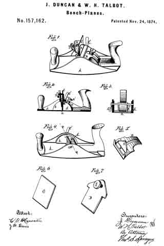
Figure 1 is a perspective view. Fig. 2 is a longitudinal vertical section through the center of the tool. Fig. 3 is a cross-section at x x, in Fig. 4, which is a perspective view of the plane-stock, the bit, segment, and pressure-plate being removed. Fig. 5 is a perspective view of the segment. Fig. 6 is a similar view of the scraper-bit. Fig. -7 is a similar view of the pressure-plate and screw.

In the drawing, A represents a small metallic plane-stock, having the form of the metallic smoothing-plane in common use, provided with the usual handles, and with a transverse throat, a. To the inner side of each cheek is secured or formed therewith a semi-circular shoulder, b, in the radius of the throat a, from which the circle is struck. In the middle, and behind the throat, a shell-like quadrant, A’, rises from the flat of the plane-stock, having the same radius as the shoulders b. c is a screw-threaded bolt tapped through the cheek of one side of the plane-stock, passing through the quadrant and the other cheek, where it receives on its threaded protruding end a tail-nut, C’, by means of which the cheeks may be slightly sprung toward each other, and thus clamp anything fitted between them. B is a sliding segment lying on the shoulders b b and quadrant A’, to the latter of which it may be secured at any point by a set or clamp screw, c’, passing through a longitudinal slot in the segment, and tapped into the quadrant. The segment is still more firmly secured by clamping its sides between the cheeks of the plane-stock by means of the screw c and nut C’. In the fore end of the segment is a transverse slot, d, from the back of which rises a plate, e, which serves as a rest for the steel scraping-bit C which is inserted in the slot, its lower end projecting through the throat a. In front of the bit a pressure-plate, D, is inserted in the slot. A set-screw, f, is tapped through the top of the plate D bearing against the bit, as does the lower edge of said plate D, forcing the bit against the bearing-plate e, thus securing the scraping-bit to the segment B, the former being adjusted to take more or less cut, like an ordinary plane-iron, while it may be adjusted to a vertical position or to any inclination with relation to the work without altering its set, an essential feature in finishing veneers of different woods and structure of fiber or grain.

What we claim as our invention, and desire to secure by Letters Patent, is —

1. The combination, with the plane-stock A having the throat a, of the shoulders b, quadrant A’, segment B, scraper-bit C, pressure-plate D, and screws c’ f, substantially as and for the purpose set forth.

2. The combination, with the plane-stock A, of the shoulder b, quadrant A’, segment B, bolt c, nut C’, scraping-bit C, pressure-plate D, and screws c’ f, as and for the purpose set forth.

JAMES DUNCAN.
WM. H. TALBOT.

Witnesses:
L. P. FOX,
JAMES K. WOODS.

No. 135,341 – Improvement In Planes For Scraping (Joseph Jones) (1873)

[paiddownloads id=”207″]135341


UNITED STATES PATENT OFFICE.

_________________

JOSEPH JONES, OF NEWARK, NEW JERSEY, ASSIGNOR TO
WILLIAM A. FREEMAN, OF SAME PLACE.

IMPROVEMENT IN PLANES FOR SCRAPING.

_________________

Specification forming part of Letters Patent No. 135,341, dated January 28, 1873.

_________________

To all whom it may concern:

Be it known that I, JOSEPH JONES, of Newark, in the county of Essex and State of New Jersey, have invented an Improvement in Scraping-Planes, of Which the following is a specification:

This invention relates to that class of implements used in smoothing the surface of hard wood and other hard material, known as scraping-planes; and it consists in the combination, with the holder which carries the scraping-tool and with suitable slotted supports arranged at the sides of the stock, of a transverse bolt and a locking-nut, in such manner that the scraping-tool may be adjusted at any angle required in the work to which the implement is applied.

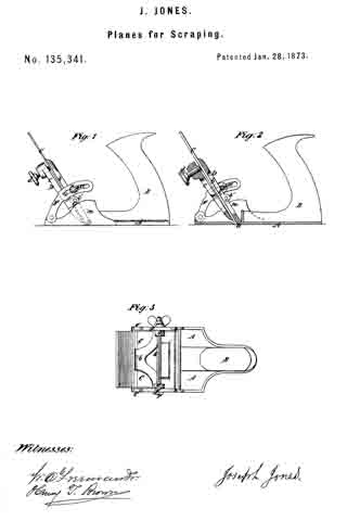
Figure 1 is a side view of an implement made according to my invention. Fig. 2 is a vertical longitudinal section of the same. Fig. 3 is a plan view of the same.

A is the stock, made of metal, and, in the main, in the ordinary manner, and provided with the handle B, whereby the requisite reciprocating movement is given to the implement when in use, and also with the upwardly-projecting cheeks m at the sides. At a, is the throat through which project the lower or scraping edges of the plane-iron C, this iron C being confined in the holder D. The holder is composed of two parts, b c, the former of which is pivoted by the lateral bearings at its lower end in close proximity to the throat a, as indicated in dotted outline in Fig. 1, and also shown in Fig. 2. The part c is attached by lugs b’ and pivots c’ to the part b, and carries at its upper end the screw d. By placing the iron C between the two parts and tightening the screw d, the iron is, of course, firmly clamped in place in the said holder. At each lateral edge of the part b of the holder is a lug or ear, g, and arranged in due relation thereto is a bar or support, F, pivoted, as shown at e’, to that end of the stock opposite the handle, and formed at its upper part with a longitudinal slot, a’, of a curvature which, when the supports are in position, as herein presently described, is on an arc more or less concentric with the pivoted point near the throat a of the holder. A transverse bolt, G, having a head, r, at one end and a nut, r’, at the other, is passed through the slots a’ of the supports just mentioned, and also through holes formed in the lugs g of the holder, in such manner that, by tightening the nut r’, the frictional hold of the head and nut of the bolt G upon the supports F will rigidly retain the same in a fixed position, and thereby insure the retention of the holder and its contained scraping-tool at any angle to which it may be adjusted. The degree of adjustment is, of course, limited only by the length of the slots in the supports F, Which latter serve to brace and sustain the tool against the strain exerted when the same is in use. Instead of having the supports pivoted, as hereinbefore described, the same may be constituted in one with the cheeks m — the latter being extended upvvard to a sufficient height, and provided With arc-shaped slots answering to those of the pivoted supports F, and for the same purpose.

What I claim as my invention is —

The combination, With the holder D having lugs g, of the slotted supports F pivoted to the stock A and the tightening-bolt G, the whole arranged and operating substantially as and for the purpose herein set forth.

JOSEPH JONES.

Witnesses:
HERBERT COTTRELL,
I. M. TAYLOR.