No. 37,694 – Improvement In Bench Planes (Seth C. Howes) (1863)

[paiddownloads id=”97″]37694


UNITED STATES PATENT OFFICE.

_________________

SETH C. HOWES, OF SOUTH CHATHAM, MASSACHUSETTS.

IMPROVEMENT IN BENCH-PLANES.

_________________

Specification of Letters Patent No. 37,694, dated February 17, 1863.

_________________

To all whom it may concern:

Be it known that I, SETH C. HOWES, of South Chatham, in the county of Barnstable and State of Massachusetts, have invented a new and useful Improvement in Bench-Planes, such as are used by joiners and other artisans in wood; and I do hereby declare that the following is a full, clear, and exact description of the same, reference being had to the accompanying drawings, making part of this specification, in which —

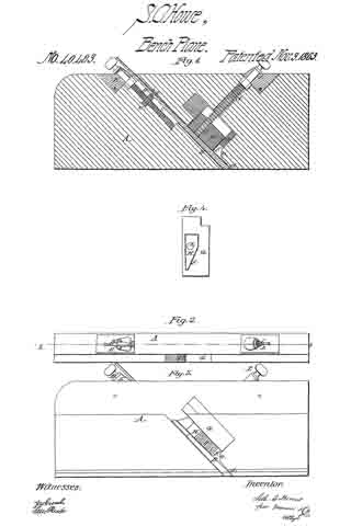
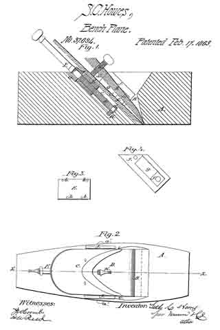
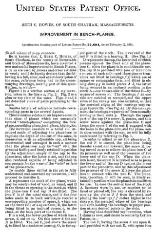
Figure 1 is a vertical section of my invention, taken in the line x, x, Fig. 2. Fig. 2 is a plan or top view of the same. Figs. 3 and 4 are detached views of parts pertaining to the same.

Similar letters of reference indicate corresponding parts in the several figures.

This invention relates to an improvement in that class of planes which are commonly termed “bench-planes,” comprising the fore-plane, smoothing-plane, jack-plane, jointer, &c.

The invention consists in a novel and improved mode of adjusting the plane-iron to regulate the depth of the cut of the same, in connection with an adjustable cap, all being constructed and arranged in such a manner that the plane-iron may be “set” with the greatest facility and firmly retained in position by the adjustment simply of the cap to the plane-iron, after the latter is set, and the cap also rendered capable of being adjusted to compensate for the wear of the “sole” or face of the plane-stock.

To enable those skilled in the art to fully understand and construct my invention, I will proceed to describe it.

A represents the stock of the plane, which may be constructed of wood, as usual, and B is the throat or opening in the stock, in which the plane-iron C and cap D are fitted. The iron C is of the usual shape, and it has four holes made in its back surface, to receive a corresponding number of spurs, b, which are on the front side of a square nut, E, the latter being fitted in an inclined recess, c, in the stock, at the back part of the throat B.

F is a rod, the lower portion of which has a screw, d, cut on it. On this screw d the nut E is fitted. The rod F, just above the screw d, is fitted in a socket or bearing, G, in the upper part of the stock. The lower end of the rod F is fitted in a bearing, H. (See Fig. 1.)

D represents the cap, the lower end of which presses against the front side of the plane-iron G, when the plane is in condition for use. The cap D is provided with pins or trunnions e e — one at each side — and these pins or trunnions are fitted in bearings f f, which are of square or rectangular form, and fitted in oblong slots g g in metal plates J J, the latter being secured in an inclined position in the stock A — one at each side of the throat B — by means of screws a’. The bearings f at one side are notched or serrated, and the upper sides of the slots g are also serrated, so that the serrated edges of the bearings may engage therewith. (See Fig. 4.) By this arrangement the bearings are prevented from casually moving in their slots g. Through the upper part of the cap D a screw, K, passes, and this screw bears against the plane-iron C and keeps the spurs b of the nut E engaged with the holes in the plane-iron, and the plane-iron in close contact with the nut, as will be fully understood by referring to Fig. 1. In order to adjust or set the plane-iron C, the rod F is turned, the plane-iron being thereby raised and lowered, the screw K being turned so as to relieve the plane-iron C of its pressure as well as of the pressure of the lower end of the cap D. When the plane-iron is set, the screw K is turned so as to press the lower end of the cap D against the lower part of the plane-iron, and by this adjustment the pressure of the screw K keeps the plane-iron in contact with the nut E. The plane-iron, therefore, it will be seen, is firmly retained in position when the plane is in condition for use. In case the sole or face of the stock A becomes worn by use, or requires to be faced or planed off, the cap is elevated by removing the plates J J from the stock and placing the bearings f f rather higher in the slots g g, the serrated edges of the bearings and slots holding the bearings in proper position at any desired points in the slots.

Having thus described my invention, what I claim as new, and desire to secure by Letters Patent, is —

The rod F, having the screw d cut upon it, and provided with the nut E, with spurs b on its outer surface, to fit in holes in the plane-iron C, in combination with the cap D, provided with the screw K and trunniouse e the f f, which are placed in slotted plates J J , and retained therein at the desired point by the serrated edges of the bearings and the slots or a equivalent means, all arranged substantially as set forth.

SETH C. HOWES.

Witnesses:
JOHN G. DOANE,
FREEMAN E. CHASE.

No. 40,483 – Improvement In Planes For Beading And Molding (Seth C. Howes) (1863)

[paiddownloads id=”99″]40483


UNITED STATES PATENT OFFICE.

_________________

SETH C. HOWES, OF SOUTH CHATHAM, MASSACHUSETTS.

IMPROVEMENT IN PLANES FOR BEADING, MOLDING, &c.

_________________

Specification forming part of Letters Patent No. 40,483, dated November 3, 1863 ; antedated October 24, 1863.

_________________

To all whom it may concern:

Be it known that I, SETH C. HOWES, of South Chatham, in the county of Barnstable and State of Massachusetts, have invented a new and useful Improvement in Planes for Beading, Molding, &c., &c. ; and I do hereby declare that the following is a full, clear, and exact description of the same, reference being had to the accompanying drawings, making a part of this specification, in which —

Figure 1 is a vertical section of my invention, taken in the line x x, Fig. 2; Fig. 2, a plan or top view of the same 5 Fig. 3, a side view of the same; Fig. 4, a detached face view of the clamp which holds the plane iron in proper position.

Similar letters of reference indicate corresponding parts in the several figures.

This invention relates to an improvement in that class of planes used by joiners for forming beads and moldings, and also for forming rabbets, and which discharge the shavings at the side of the stock.

The object of the invention is to obtain a plane of the kind specified which will discharge the shavings freely and without the liability of choking or clogging in the throat, and one also which will admit of the iron being adjusted with the greatest facility to regulate the depth of cut and admit of the iron being firmly secured in the stock.

To enable those skilled in the art to fully understand and construct my invention, I will proceed to describe it.

A represents the stock of the plane, which is constructed of wood, and of the usual form, and B is the “iron,” the lower end or cutting-edge of which is made of a form corresponding to that of the bead, molding, or rabbet to be cut. This iron has a notch, a, made in its back surface, near its upper end, and into this notch a projection or spur, b, on a nut, C, is fitted, said nut being in an inclined recess or groove, c, in the stock. The nut C is on a screw, D, the upper part of which is iitted in a metal socket, F, placed in a recess in the upper part ofthe stock. The upper part of the plane-iron is fitted in the front part of the recess or groove c, while the lower part passes through a recess, F, which is open at its side, and forms what is commonly termed the throat, to admit of the shavings out by the iron to pass out from the stock. This throat is narrow at its lower end, as shown at d, and it widens very gradually for a short distance upward, and then suddenly expands or increases in width, with a rounded front, e, as shown clearly in Figs 1 and 3.

Within this enlarged part of the throat there is fitted a metal socket or guide, G, in which a clamp, H, works. This clamp is also constructed of metal, and may be described as being formed of a rectangular bar, having one side beveled, as shown at f (See Fig. 4.) The clamp is allowed to work freely in the socket or guide G, and it is moved or operated by a screw, I, which works in an internal screw-thread, g, in the clamp, as shown in Fig. 1, and is litted in a metal socket, J, placed in a recess in the upper part of the stock. The portions of the screws I and D, which are htted in the sockets E and J, are smooth, (see Fig. 1,) and the beveled surface f is placed outward.

From the above description it will be seen that by turning the screw-rod D, the iron may be raised and lowered according to the depth of cut or thickness of shaving required, as by turning said screw the nut C is moved, and with it the iron, and when the desired set of the iron is obtained, the latter is secured in position by pressing the clamp H against it, the latter result being attained by turning the screw I. The back part of the iron is pressed by the clamp H firmly against the back part of the throat F.

In using the implement the shavings will readily pass up the lower narrow part of the throat, and in passing into the enlarged part they will turn freely the rounded corner e, and, coming in contact with the hard, smooth metal surfaces of the inner side of the socket or guide G, and the beveled surface f of the clamp H, are discharged freely from the throat, and all choking and clogging of the latter avoided.

The ordinary throats of this class of planes are very liable to choke or clog with shavings, as they have a comparatively long narrow opening at their lower parts, and are not provided with any rnetal surfaces, which have a tendency to prevent the sticking or adhering of the shavings in the throat.

Having thus described my invention, I claim, as an improved article of manufacture —

A molding-plane provided with the adjusting-nut C, screw D, the holding-clamp H, screw J , and curved throat e, all constructed and operating together, as herein shown and described.

SETH C. HOWES.

Witnesses:
JOHN G. DOANE,
FREEMAN E. CHASE.