No. 284,919 – Bench-Plane (William Steers) (1883)
[paiddownloads id=”340″]284919


UNITED STATES PATENT OFFICE.

_________________

WILLIAM STEERS, OF SHERBROOKE, QUEBEC, CANADA.

BENCH-PLANE.

_________________

SPECIFICATION forming part of Letters Patent No. 284,919, dated September 11, 1883.
Application filed January 25, 1883. (No model.)

_________________

To all whom it may concern:

Be it known that I, WILLIAM STEERS, a citizen of Canada, residing at Sherbrooke, in the county of Sherbrooke and Province of Quebec, Canada, have invented certain new and useful Improvements in Adjustable Composite Bench-Planes, of which the following is a specification, reference being had therein to the accompanying drawings.

This invention relates to improvements in bench-planes; and it consists in the devices for adjusting the cap upon the cutting-iron, the movements of the cutting-iron, and the closing of the throat of the plane to suit the different materials to be dressed, and also in the construction of the metallic body or frame of the stock, all of which will be hereinafter more fully described, and set forth in the claims.

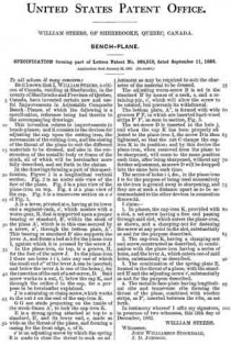
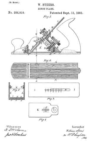
In the drawings forming apart of this specification, Figure 1 is a longitudinal vertical section. Fig. 2 is an under side view of the face of the plane. Fig. 3 is a plan view of the plane-iron on top. Fig. 4 is a plan view of the cap. Fig. 5 is a transverse section on as so of Fig. 1.

A is a lever, pivoted at a, having at its lower end a segment-rack, a’, which meshes with a worm-gear, B, that is supported upon a proper bearing or standard, B’, within the stock of the plane A’, which is in this case secured by a screw, a”, through the bottom plate, A”. This bearing or standard B’ also supports the lever A, and forms a bed at b for the plane-iron I, against which it is pressed by the screw J.

In the plane-iron, on top, is a groove, H, for the foot of the screw J. In the plane-iron I there are holes i i i, into any one of which the small end a”’ of the lever A can be inserted; and below the lever A is one of the holes j, for the insertion of the end of a set-screw, D. Said screw works in a nut, C, below the cap K, and through the orifice d in the cap, for a purpose to be hereinafter explained.

J is a straining or clamp screw, which works in the nut k on the end of the cap-iron K.

G G are studs projecting on the inside of the stock-frame A’, to lock the cap-iron K.

E is a strong spring attached at top to a standard, E’, and its lower end, e, made as wide as the throat of the plane, and forming a casing for the front edge, e, of it.

e’ is an adjusting-screw by which the spring E is made to close the throat to such an adjustment as may be required to suit the character of the material to be dressed.

The adjusting worm-screw B is set in the standard B’ by means of a neck, c, and a retaining-pin, c’, which will allow the screw to be rotated, but prevents its withdrawal.

The bottom plate, A”, is formed with wide grooves F F, in which are inserted hard-wood strips F’ F’, as seen in section, Fig. 5.

The set-screw D is inserted in the hole j, and when the cap K has been properly adjusted to the plane-iron I, the screw D is then tightened, so that the nut C clamps the cap-iron K in its position; and by this device the plane-iron, when removed from the plane to be sharpened, will come to the same position each time, after being sharpened, without any further adjustment, as screw D will be dropped into the same hole each time.

The series of holes i i, &c. , in the plane-iron I is for the purpose of being used successively as the iron is ground away in sharpening, and they are at such a distance apart as to be accommodated to the other devices in connection therewith.

I claim —

1. In planes, the cap-iron K, provided with a slot, a set-screw having a free end passing through said slot, which enters the plane-iron, as shown, and a clamping-nut for fastening the screw at any point in the slot, substantially as and for the purpose described.

2. The cap-iron K, having a clamping-nut and screw, constructed as described, in combination with the plane-iron having a series of holes, andthe lever A, which enters one of said holes, substantially as described.

3. The combination of the spring-plate E, located in the throat of a plane, with the standard E’ and the adjusting-screw e’, substantially as and for the purpose described.

4. The metallic face-plate having longitudinal ribs and transverse ribs forming the throat of the plane, combined with wooden strips, as F’, inserted between the ribs, as set forth.

In testimony whereof I affix my signature, in presence of two witnesses, this 18th day of December, 1882.

WILLIAM STEERS.

Witnesses:
JOHN WILLIAMSON STOCKDALE,
J. D. JOHNSON.

No. 227,452 – Bench-Plane (William Steers) (1880)

[paiddownloads id=”307″]227452


UNITED STATES PATENT OFFICE.

_________________

WILLIAM STEERS, OF SHERBBOOKE, QUEBEC, CANADA.

BENCH-PLANE.

_________________

SPECIFICATION forming part of Letters Patent No. 227,452, dated May 11, 1880.
Application filed February 2, 1880.

_________________

To all whom it may concern:

Be it known that I, WILLIAM STEERS, of the city of Sherbrooke, in the Province of Quebec, in the Dominion of Canada, have invented new and useful Improvements in Metallic Planes, which improvements are fully set forth in the following specification, reference being had to the accompanying drawing.

The first part of my invention relates to the device by which the knife or “iron” is adjusted to various inclinations and secured in any position to suit the various degrees of hardness and grain of the different kinds of wood on which it may be used. The second part relates to the device by which the “cap ” or “back-iron” is adjusted to suit the required angle of the knife, and at the same time the back-iron serves in place of both holder and of back-iron or cap as ordinarily used; and, thirdly, to the device by which the knife is regulated to project from the face ofthe plane.

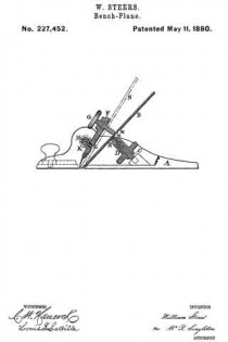
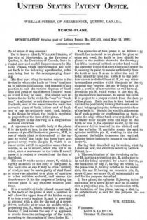
The figure in the drawing is a longitudinal sectional elevation.

A represents the metallic body of the plane. B is the knife or iron, in the back of which is a series of parallel horizontal grooves, M M, in one of which (that is determined by the extent to which the knife has been worn and ground away) works the pin E, which is secured to the nut D in a position somewhat eccentric, so as to impart, when the nut is rotated, such a movement to the knife B as will cause it to project or recede from the face of the plane.

The nut D works upon a screw, C, which is rigidly attached to the body of the plane A. The back-iron or cap F may be either entirely of steel, or may be made partly of steel fused or otherwise attached to a plate of cast-iron or other suitable material, and carries the thumb-screw G, for the purpose of locking the various parts in any required relative positions.

H is a metallic cylinder placed transversely to the body of the plane in such a position as will allow the upper face of the holder or cap F to bear evenly against it, and is provided at one end with a slot for the end of a screw-driver, and also at or near its middle with a projecting pin, K, which works in a slot, L, in the cap F, and causes the cap F to approach or recede from the cutting-edge of the knife, according to the rotation of the cylinder H.

The operation of this plane is as follows: Should the material to be planed be pine or other soft wood, the knife or iron should be placed in the position shown in the drawing; but if the material be birch or other hard wood the operator would first turn the thumb-screw G, causing its point to recede sufficiently from the knife or iron B so as to allow the nut D to be turned to raise the knife B to the position shown in dotted lines at N, or any other intermediate position which the grain of the material may require, the nut D being left at such a portion of a revolution as will have allowed the pin E, which works in the slot M, by its eccentric movement, to cause the knife B to project to a proper extent from the face of the plane. Each portion is then locked in its relative position by turning the thumb-screw G and bringing its point to bear upon the face of the knife B. Should the wood in either case be of such a grain or conformation as to require the edge of the back-iron or holder F to be nearer to or farther from the edge of the knife or iron B, the operator would, by the use of a screw-driver inserted in the slotted end of the cylinder H, partially rotate the said cylinder until the pin K, working in the slot L, caused the holder to assume the required position before locking by means ofthe thumb-screw G.

Having thus described my invention, what I claim as new, and desire to secure by Letters Patent, is —

1. The combination of the revolving cylinder H, having a projecting pin, K, and a slot in its end for being operated by a screw-driver, the back-iron or cap F, having an orifice, L, the plane-iron B, having notches in the under side, the nut D, having an eccentric pin, E, screw C, and set-screw G, all substantially as and for the purpose described.

2. In a plane, the cylinder H, having in its end a slot for a screw-driver and on its under side a projecting pin, K, in combination with the back-iron of the plane, having a slot, L, all substantially as and for the purpose described.

WM. STEERS.

Witnesses:
LOUIS S. LA BILLE,
THOMAS W. SANNER.