No. 277,556 – Bench-Plane (Daniel M. Fielding) (1883)
UNITED STATES PATENT OFFICE.
_________________
DANIEL M. FIELDING, OF DECATUR, ILLINOIS.
BENCH-PLANE.
_________________
SPECIFICATION forming part of Letters Patent No. 277,556, dated May 15, 1883.
Application filed January 31, 1883. (No model.)
_________________
To all whom it may concern:
Be it known that I, DANIEL M. FIELDING, a citizen of the United States, residing at Decatur, in the county of Macon and State of Illinois, have invented certain new and useful Improvements in Bench-Planes, of which the following is a specification.
The object of my invention is to provide a plane which is adapted to be applied to shoulders or rabbets for the purpose of squaring, cutting, and truing the same, and this in such directions as is required by the grain of the material of either or both faces of the rabbet or shoulder, in order to properly proportion it for the reception of other structures intended to be seated therein, such as doors, windows, and inset box-covers and the like.
With this object in view my invention consists in a plane having certain characteristics hereinafter described, and specifically set forth in the claims.
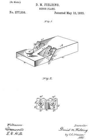
In the accompanying drawings, forming a part hereof, Figure 1 is a perspective, and Fig. 2 a transverse vertical section, of a plane constructed in accordance with my invention.
Like letters refer to like parts in both figures.
A represents the plane-stock, having a perfectly flat bottom, a, throughout its entire length. It may be of wood or of metal, and from the top of this stock projects the push and guide handle a2, the forward end of the stock being in this instance thinner than the rear end. Two separate detached independent plane-iron seats, a3 a4, are formed one upon each side of the stock, and between these seats a rib or partition, a5, remains, the lower surface of which lies in the same plane with the bottom surface of the stock, while the upper surface of said rib is in this instance inclined from the thick rear end to the front end of said stock.
B B represent the plane-irons, secured in their seats in this instance by screws b and washers b1. Any of the well-known means for securing and adjusting the irons in their seats may be substituted for the screw and washer, if desired. Each of the irons may have one or two cutting-edges, as b2 b3; but forthe purpose above set forth a single cutting-edge, b2, is preferable.
The plane is used in the following manner: Suppose, for an instance, that the edge of a door fits too snugly against the adjacent face of the casing, and that the side of the door stands od at points along the adjacent face of the casing. Instead of removing portions of the edge and face of the door, which is supposed to be true and square, the face and edge surfaces of the rabbet or shoulder of the casing is dressed down by the plane. Now, if the grain of these surfaces run contrary to each other, in which case a neat finish of both with the ordinary rabbet-plane could not be easily accomplished, all that is necessary with my improved plane is to turn it bodily to the left or right and use the desired separate plane-iron, making the cutting-strokes in the direction required by the grain of each surface, and it will be seen that each of said surfaces may be then neatly finished and closely to its adjacent surface, so that a perfect fit of the door is accomplished.
I do not claim, broadly, a double bitted or ironed plane, as these are common in molding-planes; but
What I do claim as new, and desire to secure by Letters Patent, is —
1. A plane comprising a flat-bottomed stock provided with parallel plane-iron seats on opposite sides thereof, separated by a rib, the bottom of which is in a common plane with said bottom, substantially as described.
2. As an article of manufacture, a plane having a flat uniform bottom surface, and separate independent irons arranged in seats formed in opposite edges thereof, and adapted to operate in conjunction with said bottom surface, substantially as shown and described.
3. The combination, with the stock A, having a flat bottom, a, and separate seats a3 a4, of the separate independent plane-irons B B, substantially as and for the purpose described.
In testimony whereof I affix my signature in presence of two witnesses.
DANIEL M. FIELDING.
Witnesses:
CHARLES P. HOUSUM,
JOHN S. BIXBY.