No. 1,104,454 – Plane (William E. Sparks) (1914)

[paiddownloads id=”699″]1104454


UNITED STATES PATENT OFFICE.

_________________

WILLIAM E. SPARKS, OF NEW HAVEN, CONNECTICUT, ASSIGNOR TO SARGENT &
COMPANY, OF NEW HAVEN, CONNECTICUT, A CORPORATION OF CONNECTICUT.

PLANE.

_________________

1,104,454. Specification of Letters Patent. Patented Jul. 21, 1914.
Application filed July 11, 1913. Serial No. 778,591.

_________________

To all whom it may concern:

Be it known that I, WILLIAM E. SPARKS, a citizen of the United States, residing in the city and county of New Haven and State of Connecticut, have invented certain new and useful Improvements in Planes, of which the following is a full, clear, and enact description.

This invention relates to planes, and more particularly to reversible rabbet planes.

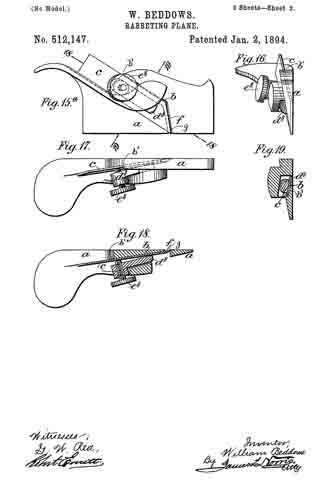
The plane selected for illustration is of the type known as a show-case plane, it being adapted to cut the rabbets of showcases by movement in either direction.

The primary object of the invention is to provide a simple, efficient form of reversible rabbet plane in which reversal may be effected without adjustment of the cutting mechanism. To this end, the plane is provided with two cutters having a novel relation to each other and to the body or stock and clamped on the stock in a novel manner.

The invention also aims to improve certain general and detail features of construction in planes of the class to which my invention relates.

To these and other ends, the invention consists in the novel features and combinations of parts to be hereinafter described and claimed.

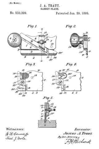
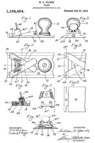
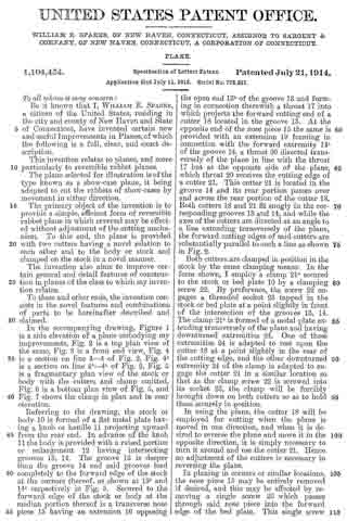
In the accompanying drawing, Figure 1 is a side elevation of a plane embodying my improvements, Fig. 2 is a top plan view of the same, Fig. 3 is a front end view, Fig. 4 is a section on line 4–4 of Fig. 2, Fig. 4a is a section on line 4a–4a of Fig. 2, Fig. 5 is a fragmentary plan view of the stock body with the cutters and clamp omitted, Fig. 6 is a bottom plan view of Fig. 5, and Fig. 7 shows the clamp in plan and in rear elevation.

Referring to the drawing, the stock or body 10 is formed of a flat metal plate having a knob or handle 11 projecting upward from the rear end. In advance of the knob 11 the body is provided with a raised portion or enlargement 12 having intersecting grooves 13, 14. The groove 13 is deeper than the groove 14 and said grooves lead completely to the forward edge of the stock at the corners thereof, as shown at 13a and 14a respectively in Fig. 5. Secured to the forward edge of the stock or body at the median portion thereof is a transverse nose piece 15 having an extension 16 opposing the open end 13a of the groove 13 and forming in connection therewith a throat 17 into which projects the forward cutting end of a cutter 18 located in the groove 13. At the opposite end of the nose piece 15 the same is provided with an extension 19 forming in connection with the forward extremity 14a of the groove 14, a throat 20 directed transversely of the plane in line with the throat 17 but at the opposite side of the plane, which throat 20 receives the cutting edge of a cutter 21. This cutter 21 is located in the groove 14 and its rear portion passes over and across the rear portion of the cutter 18. Both cutters 18 and 21 fit snugly in the corresponding grooves 13 and 14, and while the axes of the cutters are directed at an angle to a line extending transversely of the plane, the forward cutting edges of said cutters are substantially parallel to such a line as shown in Fig. 2.

Both cutters are clamped in position in the stock by the same clamping means. In the form shown, I employ a clamp 21a secured to the stock or bed plate 10 by a clamping screw 22. By preference, the screw 22 engages a threaded socket 23 tapped in the stock or bed plate at a point slightly in front of the intersection of the grooves 13, 14. The clamp 21a is formed of a metal plate extending transversely of the plane and having downturned extremities 24. One of these extremities 24 is adapted to rest upon the cutter 18 at a point slightly in the rear of the cutting edge, and the other downturned extremity 24 of the clamp is adapted to engage the cutter 21 in a similar location so that as the clamp screw 22 is screwed into its socket 23, the clamp will be forcibly brought down on both cutters so as to hold them securely in position.

In using the plane, the cutter 18 will be employed for cutting when the plane is moved in one direction, and when it is desired to reverse the plane and move it in the opposite direction, it is simply necessary to turn it around and use the cutter 21. Hence no adjustment of the cutters is necessary in reversing the plane.

In planing in corners or similar locations, the nose piece 15 may be entirely removed if desired, and this may be effected by removing a single screw 25 which passes through said nose piece into the forward edge of the bed plate. This single screw will hold the nose piece securely on the end of the bed plate in connection with a tongue and groove joint 26 formed at the meeting surfaces of the nose piece and bed plate, as shown in Figs. 1 and 4.

Without limiting myself to the construction shown, I claim:

1. In a plane, a bed plate or stock having transversely arranged throats at the opposite forward corners thereof, there being grooves in said bed plate extending rearwardly from said throats and intersecting each other, cutters adapted to fit said grooves, clamping means for said cutters located in front of the intersection of said grooves; and a knob fixed on said bed plate at the rear of such intersection; substantially as described.

2. In a plane, a bed plate having intersecting grooves, one of said grooves being deeper than the other at the point where said grooves intersect, cutters located in said grooves and overlapping each other, and a single means for clamping both cutters in said grooves; substantially as described.

3. In a plane, a bed plate having cutter-receiving grooves extending to one edge thereof, and a detachable nose piece applied to said edge of the bed plate and forming in connection with the ends of said grooves, throats for the cutting ends of the cutters; substantially as described.

4. In a plane, the combination of a bed plate or stock having transversely arranged throats at the opposite forward corners thereof, there being grooves in said bed plate extending rearwardly from said throats, cutters fitting said grooves, a single clamp to secure both of said cutters in the respective grooves at the same time, and a knob fixed to the bed plate at the rear of the cutters; substantially as described.

5. In a plane, the combination of a bed plate or stock, having intersecting cutter-receiving grooves terminating at the forward corners thereof, one of said grooves being deeper than the other at the point of intersection, cutters fitting the respective grooves, a single clamp for securing the cutters in the respective grooves, in overlapping relation, and a single detachable nose piece cooperating with the forward ends of both grooves to form throats for the cutters; substantially as described.

6. In a plane, a bed plate having cutter-receiving grooves on the upper surface thereof extending to one edge of the bed plate, a nose piece detachably secured to said edge of the bed plate between said grooves, and extensions on said nose piece located in front of the groove ends; substantially as described.

7. In a plane, the combination of a substantially flat bed plate, cutters projecting beyond the front edge of said bed plate at different points, means to secure said cutters on said bed plate, and a nose piece detachably secured to the front edge of the bed plate between said cutters and forming, in conjunction with the bed plate, throats for both cutters; substantially as described.

8. In a plane, the combination of a stock, crossed overlapping cutters having their cutting edges arranged at the respective forward corners of the stock, a single clamp for clamping both cutters on the stock at the same time, and a knob hired to the rear portion of the stock; substantially as described.

In witness whereof, I have hereunto set my hand on the 9th day of July 1913.

WILLIAM E. SPARKS.

Witnesses:
JOHN H. SHAW,
BERTHA RAY.

_________________

Copies of this patent may be obtained for five cents each, by addressing the “Commissioner of Patents, Washington, D. C.”
_________________

No. 533,329 – Rabbet-Plane (Justus A. Traut) (1895)

[paiddownloads id=”512″]533329


UNITED STATES PATENT OFFICE.

_________________

JUSTUS A. TRAUT, OF NEW BRITAIN, CONNECTICUT.

RABBET-PLANE.

_________________

SPECIFICATION forming part of Letters Patent No. 533,329, dated January 29, 1895.
Application filed October 8, 1894. Serial No. 525,202. (No model.)

_________________

To all whom it may concern:

Be it known that I, JUSTUS A. TRAUT, a citizen of the United States, residing at New Britain, in the county of Hartford and State of Connecticut, have invented certain new and useful Improvements in Rabbet-Planes, of which the following is a specification.

This invention relates to rabbet-planes, and it has for its principal object to furnish an improved plane of this general class, which may he readily converted from an ordinary rabbet-plane to a “bull-nose” plane without decreasing or adding to the number of parts of the tool.

Another object of the invention is to furnish an improved clamping-device for this kind of planes, by means of which the plane-iron or cutter may be securely and positively held substantially upon its longitudinal axis.

In the drawings accompanying and forming a part of this specification, Figure 1 is a side elevation of a rabbet-plane embodying my present invention. Fig. 2 is a front elevation of the same. Fig. 3 is a side elevation of a portion of the forward end or toe of the plane, looking toward the side opposite that shown in Fig. 1, and showing a reversible, auxiliary duplex runner in position to form an ordinary side-rabbet-plane. Fig. 4 is a view similar to Fig. 3, but showing the reversible member in position to form a “bull-nose” side-rabbet-plane. Fig. 5 is a transverse section taken in line x–x, Fig. 1, looking in the direction of the arrow and illustrating one use of the plane.

Similar characters designate like parts in all of the views.

In rabbet-planes as heretofore constructed it has been the practice to provide one form of plane for working in continuous open grooves, or cuts, and a separate, or “bull-nose,” plane for working in grooves or cuts closed at one or both ends thereof.

It is the main object of the present invention to combine the ordinary rabbet-plane and the “bull-nose” plane so that the two may be readily and quickly converted from one to the other, without decreasing or adding to the number of parts thereof, while at the same time maintaining the strength and solidity of the ordinary forms of plane of these types now in use. I attain this end by the provision of an auxiliary reversible member, or duplex runner removably secured to the forward end of the plane, in such a manner as to be fixedly held against movement laterally and longitudinally of the stock when in position thereon, and so that, when in either of its positions, one of the runners will have its sole in alignment with the sole of the stock, and will also have a vertical stop-face adjacent to the cutting edge of the plane-iron or cutter and adapted to close the chip-space or throat of the plane.

My invention also contemplates the provision of a clamp, adapted to be held positively in position substantially upon its longitudinal axis, so that the end thrust upon the cutter, when the plane is in use, will not loosen the clamp, but will be taken up by a fixed portion of the stock.

In the preferred embodiment of my invention, herein shown and described, P designates the stock of the plane, and is shown herein as comprising a body-portion 2, and a runner 3, of reduced cross-section, having the usual beveled face 4 sloping toward the outer side of said runner to form the usual narrow sole 5. This stock is shown herein as of substantially rectangular outline, and as provided at the upper rear end thereof with a handle 6, which may be of any desired construction. This handle is shown as formed separately from the stock and as secured thereto by a screw fastening but it is obvious that it might be integral with the stock. An oblique channel is shown, at 7, as extending from the upper, inner corner of the plane to the lower, outer corner thereof, and is adapted for maintaining the cutter or bit in position. The walls of this channel are shown as parallel with each other, and as intersecting the outer face of the plane in a line perpendicular with the sole thereof, so as to form an inner stop-wall for the outer side of the cutter-iron, and thereby maintain the cutting-edge of said iron perpendicular to the plane of the sole of the stock.

The plane-iron or bit is designated in a general way by B, and is shown as having parallel, longitudinal edges, and as adapted to lit snugly within the guides, 8 and 9, which form the upper and lower walls of the channel 7. This bit or cutter is also shown as beveled at its forward end to form a cutting edge 10, which, when the cutter is in position, will be substantially perpendicular to the sole of the stock, and is represented as beveled also adjacent to its lower, longitudinal edge, to conform with the outline of the beveled runner 3, and prevent interference with the work, which might result from the projection of a portion of the cutter beyond the inner, beveled edge of the runner.

The stock is shown herein as having formed upon its inner side a channel or guide-way 12, perpendicular to its sole but inclined to the sides of said stock at the same angle as is the channel 7, and adapted to position a clamping-device for locking the cutter against the walls of said channel 7, the two guide-ways or channels being shown as intersecting each other.

The clamping-device for securing the cutter is shown as comprising a locking-member or bridge-piece 13, having a body portion, non-contiguous to the stock, and two transverse terminal members or clamping faces, 13′ and 13”, the latter of which is disposed obliquely of the body-portion, so that when in position it will engage the inner face of the bit substantially upon the longitudinal axis thereof. This bridge-clamp is shown as provided with a central aperture or opening adapted for the reception of a clamping thumb-screw 14, the outer screw-threaded end of which engages a correspondingly-threaded aperture or tap, passing through the body portion of the plane, at a point substantially centrally-disposed relatively to the side-walls of the guide-way 12.

A washer 15 may be provided, if desired, between the head of the clamp-screw and the face of the bridge-piece.

It will be seen that, when the cutter is in position and the bridge-clamp is adjusted between the walls of the channel 12, if the body-portion of the clamp is forced or sprung inwardly toward the inner wall of the stock by the clamp-screw, all the pressure exerted will be transmitted to the two locking-faces 13′ and 13”, and that the cutter will be securely engaged and maintained in position, as the side edges of the clamp 13 engage against the walls of the guideway and fill the same so that there can be no movement of the clamp until the screw is released.

Pressure upon the cutter during the operation of the plane is transmitted to the clamp in such a way as to be received against the vertical stop-walls of the guide-way 12, and hence the clamp can not work loose.

At the forward end of the outer side of the stock, a channel or guide-way, shown at 16 as disposed substantially perpendicularly to the sole of the plane, is formed, and said channel is provided with a rearwardly-extending re-
cess or countersunk portion 16′, the transverse wall of which is described by a curve which is shown as approximately a semi-circle, but it will be understood that this recess or countersink might be of a different conformation, if desired. The forward end of the stock is shown herein as undercut to thepoint where the channel 7, or cutter-way, intersects the outer face of the plane to the sole of the runner thereof, but for only a portion of this distance.

An auxiliary reversible, member, designated in a general way by R’, and having reversible runners separately adapted to be brought into alignment with the main runner to form therewith a continuous sole, is shown herein as adapted to be seated within said channel or guide-way, and to be maintained against longitudinal movement, relatively to the stock, by the vertical stop walls, 17 and 18, thereof. This auxiliary runner is shown as of partially rectangular outline —
that is to say, it is formed with parallel front and rear walls, and with transverse parallel soles perpendicular to said front and rear walls. Said duplex runner is shown herein as having at each of its upper and lower ends a runner and a sole, designated, respectively, by 19, 19’, 20 and 20′. Each of said, runners is beveled to correspond with the beveled edge of the runner of the stock, one of said beveled faces being shown in Fig. 1. One end of this auxiliary runner is shown herein as of considerable length, and as having a toe-portion or nose, 20”, extending slightly beyond the forward end of the stock in the manner common to side-rabbet-planes as ordinarily constructed. The other end of said duplex runner is shown as having a very short runner formed by undercutting this end of the auxiliary member for a considerable distance, so that when said auxiliary member is secured to the stock in the position shown in Fig. 4, the construction willbe that of a “bull-nose” plane, the toe-portion or nose of which extends under the forward end of the stock and is but slightly in advance of the cutting edge of the bit. In order that said auxiliary runner may be properly positioned, without unnecessary adjustment thereof, I have shown the same as provided herein with an aperture or opening, extending through the same transversely thereof, at a point centrally located with respect to both the vertical, parallel outer walls and the horizontal, parallel outer walls thereof, and as secured to the stock, within the guide-way 16, by a locking device, which is shown herein as a screw 21, passing through the central opening in said stock and into a correspondingly-threaded opening therein, which latter opening is so placed as to be at the same perpendicular distance from the main sole (extended), as is the opening in the auxiliary, duplex runner from the soles 19′ and 20′. It will, be seen, therefore, that, when the auxiliary stock is secured in position by the screw 21, in either of its positions the sole of the corresponding runner will be in exact alignment with the sole of the runner upon the stock. The parallel, vertical walls of the duplex runner are so disposed as to engage snugly against the corresponding, forward and rearward stop-walls of the guide-way 16, so that longitudinal movement of the auxiliary runner, relatively to the stock, is positively prevented.

It will be understood that the laterally-extending recess 16′ is merely to form a seat for the nose 20″, and may be of any desired outline so long as it is of sufficient area to inclose the same; and also, that the outer faces of the stock and the duplex runner, when the parts are assembled form a continuous, plane surface, which presents no obstruction to the surface against which it may be held when the plane is in use, the head of the screw 21 being flush with or sunken below the outer face of the auxiliary runner, and the point of the clamping screw also being flush with the outer face of the stock.

By means of the reversible, auxiliary member just described it will be evident that, by simply removing the screw 21 and reversing the position of said auxiliary member, the plane may be quickly changed from an ordinary rabbet-plane to a “bull-nose” rabbet-plane and vice versa, without changing any of the parts thereof, so that the plane may be readily and quickly adapted for use for smoothing the sides of grooves or cuts which are continuous from end to end of the material being operated upon, or which extend but part-way along the material and are closed at their ends, which latter require a plane having a very short nose extending but slightly in advance of the cutter. It will also be noticed that the rearward, vertical wall of the auxiliary runner closes the throat of the plane and forms the forward wall of said throat in both of its positions.

A perfect convertible-plane is formed by the combination with the main stock of an auxiliary runner of the character described, whereby the plane may be adapted for use either as an ordinary rabbet-plane or as a “bull-nose” rabbet-plane, by the removal and re-setting of a single screw and the member secured thereby.

Having thus described my invention, I claim —

1. In a rabbet-plane, the combination with the stock and its runner, of an auxiliary member adapted to be secured to said stock and to close the throat of the plane and having oppositely-disposed runners separately adapted to be brought into alignment with the main runner upon the stock and form with said runner a continuous sole, substantially as described.

2. In a rabbet-plane, the combination with the stock and its runner, and with the cutter secured to said stock, of an auxiliary member adapted to be secured to the stock and to close the throat of the plane and formed with oppositely-disposed runners having respectively projecting and undercut portions forming auxiliary runners adapted to be separately brought into alignment with the main runner upon the stock and to form therewith a continuous sole, whereby said plane is adapted for use either as an ordinary rabbet-plane or as a “bull-nose” rabbet-plane, substantially as described.

3. In a rabbet-plane, the combination with the stock and its runner, and with the cutter secured to said stock, of a vertically-disposed channel or guide-way at the forward end of said stock, a reversible auxiliary member adapted to be seated in said guide-way and having oppositely-disposed long and short runners separately adapted to be brought adjacent to and to close the throat of the plane, and securing means in position and adapted for securing said auxiliary member in said guideway with the sole of either of its runners in alignment with the main sole of the stock, and thereby adapting the plane for use either as an ordinary rabbet-plane or as a “bull-nose” rabbet-plane, substantially as described.

4. In a rabbet-plane, the combination with a stock having a throat open at its forward side, and with a runner carried by said stock, of a reversible duplex auxiliary runner secured to the stock and adapted in either of its positions to close the throat of the plane and to form with the main runner a continuous runner and sole, and stops carried by said stock and adapted to prevent longitudinal movement of said auxiliary runner relatively to the stock, substantially as described.

5. In a rabbet-plane, the combination with a stock having an obliquely-disposed channel, a cutter mounted therein, and a vertically-disposed guide-way intersecting said channel, of a bridge clamp seated in said guide-way and held therein against movement longitudinally of the stock and having remotely-disposed locking-faces one of which is adapted to engage the rear wall of said guide-way and the other of which is adapted to engage the cutter substantially upon the axial line thereof, and a clamping-screw passed through said clamp and into the stock and adapted to bind said clamp to the cutter, substantially as described.

JUSTUS A. TRAUT.

Witnesses:
FRED. J. DOLE,
FREDERICK A. BOLAND.

No. 512,147 – Rabbeting-Plane (William Beddows) (1894)

[paiddownloads id=”500″]512147


UNITED STATES PATENT OFFICE.

_________________

WILLIAM BEDDOWS, OF NOTTINGHAM, ENGLAND.

RABBETING-PLANE.

_________________

SPECIFICATION forming part of Letters Patent No. 512,147, dated January 2, 1894.
Application filed August 27, 1892. Serial No. 444,288. (No model.) Patented in England January 28, 1892, No. 1,736.

_________________

To all whom it may concern:

Be it known that I, WILLIAM BEDDOWS, a subject of the Queen of Great Britain and Ireland, residing at Nottingham, in the county of Nottingham, England, have invented new and useful Improvements in Rabbeting-Planes, (for which I have obtained a patent in Great Britain and Ireland, No. 1,736, bearing date 28th January, 1892,) of which the following is a specification.

My invention relates to improvements in side planes or those planes wherein the cutting edge of the iron or bit lies at the side, as contradistinguished from the bottom of the plane stock, and the object of said invention is to provide a plane of the class mentioned which is adapted to smooth the side walls of narrow grooves, quirks and beveled shoulders in wood work and which is constructed in a novel manner, whereby the edge of the iron or bit will give a clear cut, the iron being firmly bedded, fiat, and of a form capable of being sharpened and adjusted in the stock, so as to be used for a long period of time.

To these ends the invention consists in the novel construction and combination of parts hereinafter described and claimed, reference being had to the accompanying drawings, wherein —

Figure 1, is a side elevation of a plane constructed according to my invention. Fig. 2, is an end elevation thereof. Fig. 3 is a cross sectional view taken on the line x–x Fig. 1. Fig. 4 is a plan view, the iron or bit and its retaining devices being removed. Figs. 5 and 6, illustrate, respectively, a face and an edge view of the plane iron or bit. Fig. 7 is a detail vertical sectional view of the iron or bit retaining plate. Figs. 8 and 9 are, respectively, plan and end views illustrating a different arrangement. Figs. 10, 11 and 12, illustrate, respectively, plan, edge, and end views of a triangular plane iron or bit. Figs. 13 and 14, illustrate, respectively, a side view and a longitudinal section of a construction particularly adapted for curved work. Fig. 15, is a detail transverse sectional view, illustrating another arrangement. Figs. 15a, 16 and 17, illustrate, respectively, a side elevation, an end view and a plan view of a further different arrangement. Figs. 18 and 19, are sectional views, taken, respectively, on the lines 18–18 and 19–19, Fig. 15a.

In said drawings the reference letter a designates the plane stock or body which is substantially triangular in section and of narrow dimensions transversely or in width and which is provided with a vertical working side face, the width of the upper part of the stock being comparatively large, so as to form a firm and strong bed or support for the iron and to give rigidity to the tool, while the lower part is extremely narrow and may be only one-tenth or one-twentieth of an inch in transverse section, so as to permit its entrance into narrow grooves in wood-work, to plane or smoothen the side walls of such grooves. Said stock is provided with an iron or bit-receiving channel b which extends from the top to the bottom of the stock a in an inclined, forward direction, as best shown in Figs. 1, 13, 15a and 20, of the drawings, and which also slants laterally, or extends in a transversely inclined direction from its commencing end b’ to its finishing end f.

In order to employ an iron or bit of flat form and having the advantages above described, in a stock which has an inclined mouth, that is to say, a mouth making any angle say from ten degrees to eighty-nine degrees with the bottom or riding edge of the plane, the iron or bit and its channel or bed are so inclined or canted with respect to the face or side of the plane stock as indicated by the reference letter b3, as to bring the cutting edge of the iron in the mouth when the iron or bit is in place in said channel. This will be better understood by reference to Figs. 1 to 6 and 15 to 19 of the drawings which show stocks with the mouth inclined at angles less than ninety degrees and by reference to Fig. 13, which represents a stock with the mouth at ninety degrees to the bottom or riding edge.

The reference letter c indicates the plane iron or bit having a cutting edge g formed at an angle with the side edge of the said iron or bit, the cutting end being of the same thickness as the remainder of the iron or bit and with a top beveled cutting edge, that is to say, the cutting edge when in place in the mouth slants away from the face, the fiat or unbeveled side of the iron being toward the bed, so that a thin or thick shaving may be produced and the acuteness of the cutting edge increased or decreased in sharpening as desired, the shavings being similar to those produced by ordinary surfacing planes in contradistinction to planes for cutting cigar lighters which have an inclined iron in a more or less rectangular stock and are designed to produce a shaving of a special form, and which cannot be used for surfacing, and which is adapted to be placed in and removed from the channel b, and when in operative position in said channel its cutting edge lies in the rearwardly inclined finishing end f of said channel.

The mouth f of the stock may be at any desired angle with respect to the bottom edge of the plane, the angle being different according as the plane is intended for surfacing soft, fibrous or hard woods, and as it is desired that the iron shall have a more or less shear cut.

The plane iron or bit c is firmly retained in position in the channel b as illustrated in Figs. 1, 2 and 3, by means of a retaining plate d which lies over the channel b and is provided with a flange d’ which bears upon the plane iron or bit c when it is forced in the proper direction by the screw e which passes through an orifice in said plate and has a screw-threaded engagement with the plane stock; a, as clearly shown.

In Fig. 15, I have shown the retaining plate held in place by a bolt e’ passing therethrough and through the stock a, a nut e2 engaging the end thereof, by turning which nut the retaining plate is tightened to clamp the plane iron or bit in place, or loosened to permit its removal.

In Figs. 8 and 9, the plane iron or bit c is shown retained in place by means of a wedge h, the retaining plate d, and its screw or bolt being dispensed with. In this construction the upper part of the stock a is enlarged so as to receive the plane iron or bit and wedge, the wedge being driven into place in the channel to forcibly hold the iron or bit within the channel.

In Figs. 10, 11 and 12 a plane iron or bit c’ is shown triangular in cross section so that it will accurately fit and fill the channel b, which is also triangular in cross section.

A plane particularly adapted for curved work is illustrated in Figs. 13 and 14 wherein the dimensions of the bottom edge of the stock a’ are greatly reduced. In these figures I have also shown a different arrangement of devices for retaining the plane iron or bit in place, that is to say, a retaining lever j and thumb screw k, the fulcrum of the lever being a bar, bridge or pivot l, fixed to or cast in one piece with the stock a’, as shown in section Fig. 14.

In Figs. 15a to 19, I have shown other means for retaining the plane iron or bit in place, wherein the letter a indicates the plane stock; b, the channel and c, the plane iron secured in the channel by the retaining block d3 and screw e3 which engages the screw socket in the retaining block d3 and bears at its inner end against the plane iron c.

It will be understood that the degree of inclination possessed by the channel b herein described may be varied to suit different conditions without departing from the scope of my invention, and that a side rabbeting plane having a stock wide at the top and narrow at the bottom so as to be capable of entering narrow grooves and yet forming a strong, firm support for a single, flat or triangular section top beveled adjustable iron or cutter, which lies in the bed of the stock which bed is inclined from top to bottom and also slants transversely of the stock and is capable of being easily clamped or secured in position in said bed, may be made with the bottom or riding edge of various lengths according as the tool is intended for straight or curved work, for rough or fine work, and also that the mode or means of clamping the iron or bit may be varied, the wedge as in Figs. 8 and 9 being preferable for deep narrow grooves and the means shown in Figs. 1, 2, 3, 13,15, 16, 17, and 18 being more desirable for shallow grooves or large work. For this reason three methods of clamping are shown and described. The plane stock is so shaped at its upper part as to be easily held in the hand of the user.

Having thus described my invention, what I claim is —

1. In a plane, the combination with a transversely narrow stock, having a vertical working side face, and provided with a channel which is inclined from top to bottom of the stock and slanted transversely of the stock, and one side wall of which is canted, whereby said channel terminates in a rearwardly inclined opening in the vertical working side face of said stock, of a plane iron located in said channel with its cutting edge lying in a rearwardly inclined direction with respect to the working face of the stock, and means for holding said plane iron in position, substantially as described.

2. In a side rabbet plane, the combination with a channeled plane stock of substantially triangular section and having a slit or mouth in the vertical side face thereof, of a uniform iron or cutter having a top beveled cutting edge angularly to the sides of the iron or cutter, and devices for holding said iron or cutter in position, substantially as described.

In witness whereof I have hereunto signed my name in the presence of two subscribing witnesses.

WILLIAM BEDDOWS.

Witnesses:
EDW. D. HEARN, Junr.,
6 Victoria Street, Nottingham.
ISAAC GALE.