No. 688,969 – Plane (Solon R. Rust And Arthur E. Rust) (1901)
UNITED STATES PATENT OFFICE.
_________________
SOLON R. RUST AND ARTHUR E. RUST,
OF PINE MEADOW, CONNECTICUT.
PLANE.
_________________
SPECIFICATION forming part of Letters Patent No. 688,969, dated December 17, 1901.
Application filed June 25, 1900. Serial No. 21,440. (No model.)
_________________
To all whom it may concern:
Be it known that we, SOLON R. RUST and ARTHUR E. RUST, of Pine Meadow, in the county of Litchfield and State of Connecticut, have invented a new and useful lmprovement in Planes; and we do hereby declare the following, when taken in connection with the accompanying drawings and the letters of reference marked thereon, to be a full, clear, and exact description of the same, and which said drawings constitute part of this specification, and represent, in —
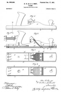
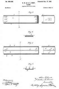
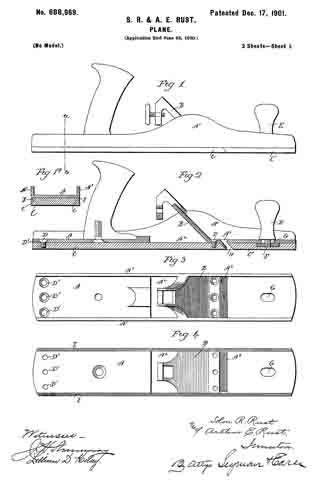
Figure 1, a view in side elevation of a plane constructed in accordance with our invention; Fig. 1a, a view thereof in transverse section on the line a b of the preceding figure; Fig. 2, a view of the plane in vertical central longitudinal section; Fig. 3, a plan view of the body of the plane stripped of all other parts; Fig. 4, a reverse plan view thereof; Fig. 5, a plan view of the removable sectional wooden face, the sections of which are separated from each other; Fig. 6, a view in transverse section on the line c d of Fig. 5; Fig. 7, a plan view of the removable sectional metal face of the plane with the sections drawn apart; Fig. 8, a view in transverse section on the line e f of the preceding figure.
Our invention relates to an improvement in that class of bench-planes designed for smoothing as distinguished from beading or rabbeting, and more particularly to smoothing-planes having metal bodies, the object being to produce at a low cost for manufacture a simple and strong plane constructed with particular reference to its adaptation to have a metal or a wooden face applied to it interchangeably, so as to readily adapt it to be used in situations requiring wooden faces as well as in situations requiring metal faces.
With these ends in view our invention consists in a plane having certain details of construction and combinations of parts, as will be hereinafter described,and particularly recited in the claims.
In carrying out our invention as herein shown the metal body A of the plane has cast integral with it an inclined cutter-supporting bed B, the opposite edges of which are supported or trussed by longitudinal flanges A’, rising from the opposite edges of I the upper face of the body. As shown, these flanges extend throughout the length of the body for increasing the strength thereof; but this is not essential. These flanges A’, as shown, are raised at points opposite the bed B, but elsewhere are straight and uniform in height. The said bed is provided for supporting the cutter, (not shown,) which may be of the usual construction and which is secured in place and adjusted in any desired manner. For the purpose of casting the said integral cutter-supporting bed without the use of cores a large casting-opening A2, which is located directly below the bed, is formed. This opening performs no function in the completed plane, but, as aforesaid, permits the body A to be cast without the use of a core, whereby the expense of producing the plane is greatly reduced. The body. A is also formed with a throat-opening A2, located directly in front of the casting-opening aforesaid and permitting the shavings removed by the cutter to escape upward through the plane.
To adapt the plane to be used in situations requiring wooden as well as metal faces, we design to provide each plane-body with interchangeable faces made of wood and of metal, respectively, these faces being constructed to correspond in size to the lower face of the body, so as to completely cover the casting-opening A2, formed therein.
These removable faces of wood and metal may be formed in one piece or in sections, as desired. As an illustration of their construction we have shown a sectional wooden face composed of a long rear section C and a short forward section C’. The said wooden section C is secured in place by screws D passing downward into it through the body of the plane, which for that purpose is formed with screw-holes D’, while the forward section is adjustably secured in place by means of a handle E, having a threaded stud F passing downward through an elongated slot G, formed in the forward portion of the body. The stud F is entered into the said forward section C’, which by turning the handle E is clamped against the forward end of the lower face of the body, so as to be held firmly in place; but as the adjacent ends of the two sections wear so as to unduly increase the opening H, Fig. 2, between them below the throat-opening A3 the forward section is moved rearwardly, so as to take up this wear by loosening the handle E.
As shown in Fig. 1a of the drawings, the lower face of the body is provided with two parallel centering-flanges I I, the inner faces of which are beveled and which insure the centering of the removable face when it is applied to the body; but these flanges are not necessarily employed, although we prefer to use them. To coact with the beveled inner faces of the flanges I I, the upper corners of the sections C and C’ are beveled, as shown at c in Figs. 1a and 6. When the removable face is made in sections, we preferably form the forward sections with two rearwardly-extending fingers J J, Fig. 5, which extend across the ends of the throat-opening A3, so as to prevent the shavings from clogging.
The removable metal face of the plane shown in Figs. 7 and 8 of the drawings comprises a long rear section K and a short forward section K These sections are reinforced and strengthened by the formation upon their upper faces of longitudinal side ribs L L and a longitudinal central rib L’. The rib L’ is enlarged near its ends to form posts L2 L2, which are internally threaded for the reception of the screws which hold it in place by passing down through the body of the plane, while the rib L’ of the forward section K is formed with a corresponding post L3 for the reception of the threaded stud F of the handle E. As shown in Fig. 8, the upper outer corners of the side ribs L of the sections K K’ are beveled, as at k, for coaction with the beveled inner faces of the centering-flanges I of the body of the plane.
Having fully described our invention, what we claim as new, and desire to secure by Letters Patent, is —
1. In a bench-plane, the combination with a metal body having an integral cutter-supporting bed both edges of which are supported or trussed by the body which is formed with a casting-opening located directly beneath the said bed, of a removable face adapted to be applied to the lower face of the said body to which it corresponds, and extending entirely over the said casting-opening.
2. In a bench-plane, the combination with a metal body having an integral cutter-supporting bed, both edges of which are supported or trussed by the body which is formed with a casting-opening located directly beneath the said bed, of a removable sectional face adapted to be applied to the lower face of the said body to which it corresponds in size, and extending entirely over the said casting-opening.
3. In a bench-plane, the combination with a metal body having an integral cutter-supporting bed both edges of which are supported or trussed by the body which is formed with a casting-opening located directly beneath the said bed, and with a throat-opening located in front of the said casting-opening, of a removable sectional face adapted to be applied to the lower face of the body so as to entirely cover the said casting-opening, and comprising a forward section which is longitudinally adjustable for taking up wear at the said throat-opening.
4. In a bench-plane, the combination with a metal body having an integral cutter-supporting bed both edges of which are supported or trussed by the body which is formed with a casting-opening located directly beneath the bed, of removable interchangeable metal and wooden faces adapted to be applied to the lower face of the body to which they correspond in size and the said casting-opening in which they entirely close.
5. In a bench-plane, the combination with a metal body having an integral cutter-supporting bed both edges of which are supported or trussed by the body which is formed with a casting-opening located directly beneath the bed and with a throat-opening located in front of the said casting-opening, of a removable sectional face adapted to be applied to the lower face of the body to which it corresponds in size, and the said casting-opening in which it entirely closes, the forward section of the said face being made longitudinally adjustable for taking up wear at the said throat-opening, and formed at its rear end with rearwardly~extending lugs which extend across the said throat-opening.
In testimony whereof we have signed this specification in the presence of two subscribing witnesses.
SOLON R. RUST.
ARTHUR E. RUST.
Witnesses:
WILLIAM McALPINE,
E. L. MORLEY.

