No. 146,588 – Improvement In Bench-Planes (Henry A. Gatley) (1874)

UNITED STATES PATENT OFFICE.
_________________
HENRY A. GATLEY, OF SOUTH BOSTON, MASSACHUSETTS.
IMPROVEMENT IN BENCH-PLANES.
_________________
Specification forming part of Letters Patent No. 146,588, dated January 20, 1874; application filed December 20, 1873.
_________________
To all whom it may concern:
Be it known that I, HENRY ALLEN GATLEY, of South Boston, in the county of Suffolk and State of Massachusetts, have invented a new and useful Improvement in Bench-Planes, of which the following is a specification:
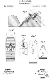
Figure 1 is a vertical longitudinal section of a plane to which my improvement has been applied. Fig. 2 is a detail section of the same, taken through the line x x, Fig. 1. Fig. 3 is a detail view of the plate, swiveled screw, and movable nut. Fig. 4 is a detail view of the plane-irons. Fig. 5 is a detail view of the locking-plate.
Similar letters of reference indicate corresponding parts.
My invention has for its object to furnish an improved attachment for jack and other hand planes, which will enable the plane-irons to be easily, accurately, and quickly attached, detached, and adjusted without hammering, and without any danger of springing the plane and making it untrue, and which shall be simple in construction and convenient in use. The invention consists in the plate, the swiveled screw, and its movable nut, in combination with the plane-irons, and the locking-plate and its screws for securing the said plane-irons adiustably to a plane-stock, as hereinafter fully described.
A represents the plane-stock, which may be made of wood or iron, and about the construction of which there is nothing new. B are the plane-irons, which are constructed and secured to each other in the ordinary manner. C is a plate, which is let into the stock A at the upper part of the inclined seat for the plane-irons B, so that its upper surface may be flush with the surface of the said seat, and which is secured to said stock by four screws. To the upper part of the lower side of the plate C are secured two lugs, C’, to which is swiveled a hand~screw, D, the hand-piece of which projects above the stock A, so that it can be conveniently operated. Upon the screw D, between the lugs C’, is placed a nut, E, which is made with a toe upon its upper edge, which projects through a slot in the plate C, and enters a hole in the plane-irons B, so that the said plane-irons may be adjusted by turning the screw D. F is the locking-plate, which is placed upon the upper side of the plane-irons B, and has a hole formed in its lower part to receive a screw, G, which passes through a hole in the plane-irons B, and is screwed into a screw-hole in the plate C. The lower part of the hole through the plate F is made large to allow the head of the screw G to pass through, and its upper part is made narrow to fit upon the body of the said screw G, as shown in Fig. 5. H is a hand-screw, which passes through a screw-hole in the plate F, and the forward end of which rests against the plane-irons B, so that, by turning the hand-screw H forward, the plate F acts as a lever to lock the plane-irons B securely in place.
Having thus described my invention, I claim as new, and desire to secure by Letters Patent —
The plate and lugs C c’ c’, swiveled screw D, and movable nut E, in combination with the plane-irons B, and locking-plate F and its screws G H, for securing the said plane-irons adjustably to a plane-stock, substantially as herein shown and described.
HENRY ALLEN GATLEY.
Witnesses:
JOHN T. DODGE,
JOHN McDONALD.


