No. 778,922 – Woodworking-Tool (Justus A. Traut) (1905)
UNITED STATES PATENT OFFICE.
_________________
JUSTUS A. TRAUT, OF NEW BRITAIN, CONNECTICUT.
WOODWORKING-TOOL.
_________________
SPECIFICATION forming part of Letters Patent No. 778,922, dated January 3, 1905.
Application filed June 6, 1904. Serial No. 211,258.
_________________
To all whom it may concern:
Be it known that I, JUSTUS A. TRAUT, a citizen of the United States, residing in New Britain, in the county of Hartford and State of Connecticut, have invented certain new and useful Improvements in Woodworking-Tools, of which the following is a specification.
This invention relates to woodworking tools or implements of the general class in which cutters are adjustably fixed in place — as, for instance, in spokeshaves and analogous artices.
My present improvement relates to the construction and mounting of the cutter and of the means for attaching the cutter and adjusting the same on the tool or implement.
For the purpose of illustrating my present improvement I have shown the same applied to a spokeshave.
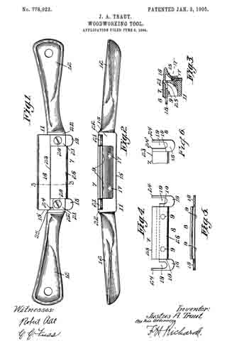
In the drawings accompanying and forming a part of this specification, Figure 1 is a plan view of a spokeshave provided with my present improvements. This view is taken with the cutter uppermost, this arrangement being adopted for convenience of illustration. Fig. 2 is a side elevation as seen from the right hand in Fig. 1. Fig. 3 is a cross-sectional view in line 3 3 of Fig. 1. Fig. 4 is a plan view of the cutter mounted on its carrier. Fig. 5 is a side elevation thereof as seen from the right hand, and Fig. 6 shows an alternative form of the end stops on the blade-carrier.
One of the features of the present improvements relates to the manner in which the cutter is mounted on the implement and by which the strains due to the clamping down of the retaining or binding devices are applied directly to a cutter-carrier, this being accomplished in such a manner as to leave the cutter normally free of such strain or cramping action as would tend to interfere with the proper holding of the same or would tend to spring and deflect the cutter.
My present improvements in the preferred form in which I have illustrated them in the present case are adapted for holding the cutter rigidly in place without applying pressure against the ends of the cutter, and at the same time the clamping of the cutter-carrier is effected by a direct pressure in one direction I only and is accomplished by the clamping action applied to relatively large surfaces, thus producing an efdcient holding of the parts together without producing the deiiection of the cutter or injurious strains in any part of the same. In this connection it will be remembered that the steel of which the cutter edge should be made must be of a high quality, whereas a more ductile and flexible quality of metal is desirable for use in making the carrier or any part of the implement which is subjected to intense strains or pressure. By means of the construction herein illustrated these objects are accomplished, the cutter proper (designated in a general way by 7) being made of relatively hard steel of high quality, while the carrier (designated in a general way by 8) is made of sheet steel or other suitable metal of a relatively tough and flexible character.
Another feature of the improvement relates to the manner of connecting the cutter onto its carrier by uniting the parts together by attaching devices — as, for instance, the rivets 9, located at some distance from the ends 10 of the cutter. In this way I obtain flexibility of the end portions of the carrier, allowing these to spring somewhat, and thus holding the cutter firmly in place without subjecting the cutter-blade itself to the deflecting strain. By this means a slight springing of the implement is prevented from affecting the fastening of the cutter in place, either as to the position of the cutter or the degree of security with which it is held, and by this means also I provide for using a lesser degree of precision in the making of the several parts, as well as for the complete interchangeability of the cutters with a lesser degree of precision in the manufacture of the implement, all of which results and objects are of practical importance and value in this art.
The stock of the tool is designated in a general way by 11 and comprises hand-grips 12 and a body portion 13, to which a sole-carrying member or guard-plate 15 is adjustably secured, the sole 16 whereof may be adjusted relative to the plane of the blade by means of set-screws 17, passing through elongated holes 17′ in the sole-carrying member. It will be seen that the ends 18 of the carrier project beyond the ends 10 of the blade and that they have ways 19 for suitable set-screws 20 for securing the blade to the body of the stock. Blocks 21 may be placed upon the top of the end portions of the carrier and lie between the ends of the blade and shoulders 22 of the stock to add to the finish of the instrument and to assist in the securernent of the carrier. The edge 23 of the blade may be adjusted toward and from the sole to regulate the cut by means of shifting the carrier back and forth and tightening the set-screws after it has been adjusted to the desired position.
It will be seen that the ends of the carrier project beyond the ends of the blade and that the carrier is secured to the blade inwardly of such ends whereby the strain of clamping or of working will be neutralized by the yieldability of the carrier to thereby protect and preserve the blade. The form of blade here employed is one made of a plate of metal having a cutting edge, as 23, along one of its sides, and the carrier is also in the form of a plate of metal overlaying the blade at the side or edge, as 26, opposite the cutting edge.
In using the implement the workman will from time to time grind away the edge 23 of the cutter-blade, the cutter being set forward toward the guard-plate or sole 15. The extending ends 24 of the said carrier are represented in Fig. 4 reaching forward to engage the edge or face 25 of the member 15 to limit the forward adjustment of the cutter, and it is intended that these ends when so constructed shall be ground away from time to time accordingly as the cutter-blade becomes narrower after continued use, so that said ends 24 of the carrier constitute stop devices for enabling the workman to set the cutter in the proper position. For convenience said stop ends are shown formed on the outer sides of the slots 19; but, if desired, they may be formed on the inner side of the said slot, or both sides, as indicated at 24 24′ in Fig. 6.
Having thus described my invention, I claim —
1. A cutting-tool embodying a stock, an unyielding blade, and a yieldable connection between the blade and stock andrrigidly secured to each.
2. In a woodworking-tool, the combination with a stock portion having a sole, of a resilient blade-carrier adjustably secured to the stock adjacent to the sole and intermediate the blade and stock, and a rigid blade having an edge and secured intermediate the ends of said edge to such carrier.
3. A woodworking-tool, comprising a stock portion, a rigid blade having a cutting edge, a relatively yieldable carrier rigidly secured to the blade inward of the ends of said edge and intermediate the blade and stock, and means for adjustably securing said carrier to the stock and engaging the same at points beyond the said ends of the blade edge.
4. A woodworking-tool comprising a stock portion, a rigid blade, a relatively yieldable carrier rigidly secured to the blade inward of its ends, means for adjustably securing said carrier to the stock, and stop-faces on the carrier to limit its forward adjustment.
5. A blade for a woodworking-tool, embodying a rigid plate having a cutting edge upon one side, a resilient carrier secured to the other side and projecting therebeyond and having securing means at such projecting portion.
6. A woodworking-tool having a stock, a guard carried thereby and adjustable relative to the position of the cutter, a cutter rigidly secured inwardly of its ends to a carrier; said carrier; means to secure the carrier to the stock; and stop-faces on the carrier to limit its forward adjustment.
7. In a woodworking-tool the combination with a stock, of a resilient carrier-bar clamped with one face adjacent to the stock, a rigid cutting-blade rigidly secured to the other face of said resilient bar sufficiently remote from its clamped portion to constitute the bar a resilient connection between the blade and the stock, and means to clamp said carrier-bar to the stock.
JUSTUS A. TRAUT.
Witnesses:
W. J. WORAM,
E. G. HOFFMAN.