No. 124,435 – Improvement In Spoke-Shaves (Jacob Groben) (1872)

[paiddownloads id=”192″]124435


UNITED STATES PATENT OFFICE.

_________________

JACOB GROBEN, OF BUFFALO, NEW YORK, ASSIGNOR TO HIMSELF AND
SAMUEL D. SIKES, OF SAME PLACE.

EMPROVEMENT IN SPOKE-SHAVES.

_________________

Specification forming part of Letters Patent No. 124,435, dated March 12, 1872.

_________________

Specification describing certain Improvements in “Spoke-Shaves,” invented by JACOB GROBEN, of Buffalo, in the county of Erie and State of New York.

Nature of the Invention.

This invention relates to certain improvements in spoke-shaves, and it consists of the combination of certain parts as will hereinafter be set forth.

General Description.

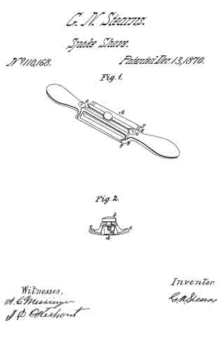
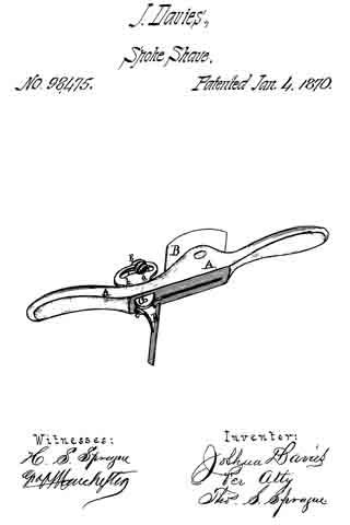
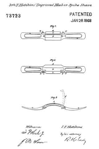
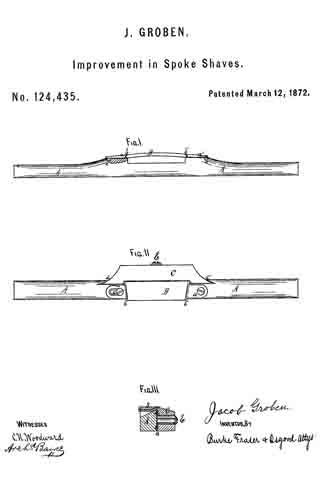
In the drawing, Figure 1 is a back elevation. Fig. 2 is a bottom-plan view. Fig. 3 is a cross-section.

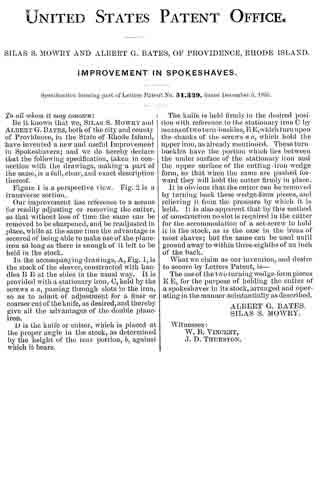
A represents the stock, B the cutter or knife, and C the face-guide. The knife is of a rectangular form, without lugs or ears to hold it; but has, instead, slanting edges, which are chamfered off, and which fit in metal sockets a a’, having slanting-grooves b b’, into which these edges set. These goooves are set slanting toward the front, to prevent the knife from slipping out, but more particularly to allow the knife to be set forward whenever the edge becomes worn or ground down, so that the space between the knife and guide may be kept always at the right adjustment. In order to hold the knife in position after it is set forward, I provide one or both of the sockets a a’ with a slot, c, through which a set-screw passes, by which the sockets can be set a little forward, as may become necessary, to keep the knife in proper place. On the under side of the sockets I form lugs e e, which fasten into the wooden stock by the pressure of the screw. The face-guide C, which graduates the cutting, works up and down in the grooves d d’, formed in the side of the stock A. It is held at any height by means of a single screw, E. By these simple devices the throat can be set at any size, and down to the very smallest space, so that cross-grained stuff can be worked just as well as straight stuff, and prevents the knife “eating ” into the wood.

This device of mine makes a very simple but very durable spoke-shave, only being required that the knife should be renewed occasionally to last a long time. It will adjust to a curved as well as a straight-cutter, and will be excellent for sweep-work.

Claim.

The slotted plates a a’, formed with the lugs e, and inclined grooves b b’, in combination with the knife B, and with the movable face guide-plate C, and its adjusting-screw E, all constructed and operating as set forth.

ln witness whereof I have hereunto signed my name in the presence of two subscribing witnesses.

JACOB GROBEN.

Witnesses:
J. R. DRAKE,
C. N. WOODWARD.

No. 110,168 – Improvement In Spoke-Shaves (George N. Stearns) (1870)

[paiddownloads id=”176″]110168


United States Patent Office.


GEORGE N. STEARNS, OF SYRACUSE, NEW YORK.

Letters Patent No. 110,168, dated December 13, 1870.
_________________

IMPROVEMENT IN SPOKE-SHAVES.

_________________

The Schedule referred to in these Letters Patent and making part of the same.

_________________

To all whom it may concern:

Be it known that I, GEORGE N. STEARNS, of the city of Syracuse, in the county of Onondaga and State of New York, have invented a new and improved Mode of Spoke-Shave; and I do hereby declare that the following is a full, clear, and exact description thereof, reference being had to the accompanying drawings and to the letters of reference marked thereon making a part of this specification, in which —

Figure 1 is a perspective view of the same.
Figure 2 is a sectional view, showing the gauge, one on each side of the knife, and the adjusting-screw inserted in the stock.

This invention relates to a new adjusting spoke-shave.

One object of my invention is in adjusting both sides of the gauge iron; the arms at the same time, thereby presenting a true and even cut the entire length of the knife.

To enable others skilled in the art to make and use my invention, I will proceed to describe its construction and operation.

In the accompanying drawings —

A represents the stock, which may be made any suitable shape or size, and of wood or metal. I prefer to make it in the shape shown in the drawing A, and of metal.

b represents the screw, inserted in the stock A for the adjusting of the gauge e e to and from the knife d.

The gauge e e is fastened to the stock A by the means of two bolts F F at the end of the arms g g.

The knife d is fastened to the stock A by the means of two screws C C, the knife d being stationary.

I am aware that other spoke-shaves have been constructed before my invention in which adjusting-gauges have been used in conjunction with knives, but such gauges and substances were differently arranged from mine, and are liable to many serious objections, which are removed by my arrangernents.

Therefore, I do not claim, broadly, the adjusting-gauge when arranged upon a different principle from that involved by my arrangements.

Having thus described my invention,

What I claim as new, and desire to secure by Letters Patent, is —

The spoke-shave herein described, consisting of stock A, gaugee e, constructed, arranged, and operating substantially as described.

GEO. N. STEARNS.

Witnesses:
A. C. MESSENGER,
HARRY GIFFORD.

No. 98,475 – Improvement In Spoke-Shave (Joshua Davies) (1870)

[paiddownloads id=”161″]98475


United States Patent Office.


JOSHUA DAVIES, OF MUSKEGON, MICHIGAN.

Letters Patent No. 98,475, dated January 4, 1870.
_________________

IMPROVEMENT IN SPOKE-SHAVE.

_________________

The Schedule referred to in these Letters Patent and making part of the same.

_________________

To all whom it may concern:

Be it known that I, JOSHUA DAVIES, of Muskegon, in the county of Muskegon, and State of Michigan, have invented a new and useful Improvement in Spoke-Shaves; and I do declare that the following is a true and accurate description thereof, reference being had to the accompanying drawings, and to the letters of reference marked thereon, and being a part of this specification, in which the drawing is a rear elevation.

The nature of this invention relates to an improvement in that class of wood-working tools, known as spoke-shaves, and consists in constructing the same with an adjustable guide-gauge, so that the tool may be guided to plane square, or any desired angle.

In the drawing —

A represents a spoke-shave, provided with the usual bit B.
C is a pair of lugs, cast on the handle of the spoke-shave, in line with the throat, which extends their length.

Between these lugs is pivoted a guide-gauge, D, which is adjustable so as to direct the cut of the bit at right angles thereto, and to form a polygonal surface, it having a sweep of forty-five degrees for that purpose, and is secured by screw a passing through its quadrant b, into the lug E, which is cast on the spoke-shave, as shown.

What I claim as my invention, and desire to secure by Letters Patent, is —

The spoke-shave A, having cast therewith the lugs E and C, and having pivoted, in the latter, the guide-gauge D, substantially as and for the purpose set forth.

JOSHUA DAVIES.

Witnesses :
H. S. SPRAGUE,
M. VAN ALLEN.

No. 97,802 – Improvement In Spoke-Shave (Joseph A. Perley) (1869)

[paiddownloads id=”157″]97802


United States Patent Office.


JOSEPH A. PERLEY, OF LYNN, MASSACHUSETTS, ASSIGNOR T0 HIMSELF AND WILLIAM H. PERLEY, OF SAME PLACE.

Letters Patent No. 97,802, dated November 14, 1869.
_________________

IMPROVEMENT IN SPOKE-SHAVE.

_________________

The Schedule referred to in these Letters Patent and making part of the same.

_________________

To all persons to whom these presents may come:

Be it known that I, JOSEPH A. PERLEY, of Lynn, of the county of Essex, and State of Massachusetts, have made a new and useful invention, having reference to Spoke and Heel-Shaves; and I do hereby declare the same to be fully described in the following specification, and represented in the accompanying drawings, of which —

Figure 1 is a top view,
Figure 2 a bottom view, and
Figure 3, a transverse section of a heel-shave, as provided with my invention, which consists in the combination and arrangement of a double-edged or duplex knife, two adjustable throat-pieces, and the two handles, the whole being substantially as hereinafter explained, and also as exhibited in the said drawings.

In such drawings —

A A denotes the two handles of the implement.

The duplex knife, shown at B, has two cutting-edges, arranged as shown at b b, it being fastened, by means of screws c c, to the handles A A, so as to form with them a stock.

Each of these handles is shaped or provided with inclined beds d d at its inner part, to receive and give support to the next adjacent ends or parts of two movable bars or throat-pieces, C C, which are fastened to the handles by clamp-screws e e e e, that screw into the throat-pieces, and pass through slots f f f f, made in the handles transversely thereof.

With the double-edged knife, and the handles and two throat-pieces constructed and combined or arranged as represented, one of the knife-edges, with its throat-piece, may be adjusted to make a “fine cut,” and the other knife-edge and throat-piece may be arranged to make a coarser or coarse cut, the same admitting of the implement being used both for paring down, or rough cutting and for finishing a heel, a work usually accomplished heretofore by two separate shaves or implements.

I claim the combination of the two handles, the double-edged knife, and the two throat-pieces, substantially in manner as specified.

JOSEPH A. PERLEY.

Witnesses:
R. H. EDDY,
S. N. PIPER.

No. 73,723 – Improvement In Spoke-Shaves (Seth T. Hutchins) (1868)

[paiddownloads id=”135″]73723


United States Patent Office.


SETH T. HUTCHINS, OF NORTH ANSON, MAINE, ASSIGNOR TO HORACE A.
LATHROP, OF SHARON, MASSACHUSETTS.

Letters Patent No. 73,723, dated January 28, 1868.
_________________

IMPROVEMENT IN SPOKE-SHAVES.

_________________

The Schedule referred to in these Letters Patent and making part of the same.

_________________

TO ALL PERSONS TO WHOM THESE PRESENTS MAY COME:

Be it known that I, SETH T. HUTCHINS, of North Anson, in the county of Somerset, and State of Maine, have invented a new and useful Improvement in Heel or Spoke-Shaves; and I do hereby declare the same to be fully described in the following specification, and represented in the accompanying drawings, of which —

Figure 1 is a. top view,
Figure 2 a bottom view, and
Figure 3 a side elevation of a spoke or heel-shave provided with my improvement.

In carrying out my invention, I not only make the adjustable throat-piece or gauge separate from two buttresses, so applied to the stock as to be capable of being moved or adjusted thereon, in order to properly adjust the throat-piece relatively to the knife or cutter, but I hinge the throat-piece to one of the said buttresses in a manner to enable the throat-piece to be turned aside or away from the knife, in order to allow the latter to be sharpened, as occasion may require; the adjusting abutments of the throat-piece remaining in the mean while undisturbed in their positions relatively to the stock. After the sharpening of the knife may have been effected, the restoration of the throat-piece to place against the abutment, away from which it was moved, can be accomplished, by simply turning the throat-piece down thereupon.

In the drawings, A denotes the stock, made in the usual form, and having two handles a a. B is the knife or cutter, fastened in or to the stock, C is the gauge, and D E its two adjustable abutments, each of the latter being held to the stock by means of a clamp-screw, b, going through a slot made in such abutment; the same being so as to enable the distance of the gauge or throat-piece C from the cutting-edge ofthe knife to be either increased or diminished, as circumstances may require. The gauge C is hinged, at or near one extremity, to the abutment E, and at its other end it bears against the other abutment, which is formed with a shoulder or bearing-surface for the gauge to rest on. This application of the gauge enables it to be moved from the abutment D into the position denoted by the dotted lines at G’ in fig. 3.

I do not claim merely applying the gauge to the stock, so as to be adjustable or capable of being adjusted nearer to or further from the knife, in order to either increase or diminish the chip-throat or passage between the knife and the gauge; but

1. I do claim the combination of the separate abutments D E, applied to the stock A, so as to be adjustable, in manner as described, with the gauge C hinged to one of such abutments, and being separate from the other, and to operate with respect to it substantially as explained.

2. I also claim the application of the gauge to its adjusting-devices, so as to be removable from them or either of them, and the knife, when the means of the adjustment of the gauge is held stationary relatively to the stock, as described.

SETH T. HUTCHINS.

Witnesses :
R. H. EDDY,
SAMUEL N. PIPER.

No. 55,599 – Improvement In Spokeshaves (Leonard Bailey) (1866)

[paiddownloads id=”118″]55599


UNITED STATES PATENT OFFICE.

_________________

LEONARD BAILEY, OF BOSTON, MASSACHUSETTS.

IMPROVEMENT IN SPOKESHAVES.

_________________

Specification forming part of Letters Patent No. 55,599, dated June 19, 1866.

_________________

To all whom it may concern:

Be it known that I, LEONARD BAILEY, of Boston, in the county of Suffolk and State of Massachusetts, have invented an Improved Spokeshave; and I do hereby declare the same to be fully described in the following specification, and represented in the accompanying drawings, of which —

Figure 1 denotes a top view, Fig. 2 a front elevation, Fi g. 3 a transverse section, and Fig. 4 a longitudinal section, of it.

In carrying out my invention I construct the stock of the spokeshave in two separate parts. and so that each of its handles shall be divided into two parts length wise, in manner as shown at a a’ in Figs. 1, 2, and 4. The two lowermost parts, a’ a’, of the handles I combine in one piece with the cutter rest or supporter — that is, so as to extend in opposite directions therefrom — and I also combine the other two or upper parts, a a, of the handles with the adjustable shank-piece c, so as to be in one piece therewith and to extend in opposite directions from it, in manner as exhibited in the figures.

The cutter or shave iron d, resting on the part b, I secure thereto by means of a clamp-bar, e, which is arranged on the cutter and directly over the part b, and is held in place (and so as to conbine the cutter to the said part D) by means of two screws, f f, which go through the lower parts of the handles and screw through the said clamp-bar e, each of such screws being arranged at right angles, or thereabout, with the lower or bearing surface of the part b.

Furthermore, the clamp-bar is caused, near its ends, to abut against two shoulders, i i, formed in or on the stock. These shoulders are arranged in front of the clamp-bar, and not only serve to prevent the downward strain of the screws from breaking the said screws, but co-operate with the screws in setting the bar closely against the cutter or shave-iron, so as to confine it firmly to its bed.

The parts a a touch the parts a’ a’ simply at or near their extremities, the same being in order that such parts a a, with the extension portion c, may constitute a bow or curved spring, to raise the said portion relatively to the cutter, and so as to increase the throat of the implement.

The screws f f are to extend through the parts a a, and screw into nuts g g, so applied to them as to act against the said parts a a, the said nuts and screws serving to effect a counter-movement of the part c, for the purpose of disconnecting the throat of the spoke shave.

The arrangement of the screws f f, the shoulders i i, and the clamp-bar e relatively to the cutter or iron d, the bed on which it rests, and the bottom, surface of the part b renders the clamp very efficient in holding the cutter down to the bed, however the clamp, by the action of the screws, is driven downward in a direction which is at an obtuse angle, its surface in contact with the plane-iron. The screws f f, by their arrangeinent, perform the duty not only of holding the clamp down upon the plane iron, but of co-operating with their nuts in springing the upper parts, a a, ot the handle, so as to regulate the distance of the throat-piece c from the plane-iron.

What I claim in the above improved spoke-shave is as follows:

1. The combination of the screws f f and nuts g g, or their equivalents, with the clamp-bar e, and with the stock divided length wise into two parts or portions, constructed substantially in manner and so as to operate as described.

2 The arrangement of the clamp-bar e with the screws f f and nuts g g, and with the stock divided lengthwise into two parts or portions, constructed substantially in manner and so as to operate with the said screws and nuts, substantially as set forth.

3. The combination and arrangement of the shoulders i i with the screws f f, the clamp-bar e, the cutter d, and bed b, or the stock, substantially as set forth.

LEONARD BAILEY.

Witnesses:
R. H. EDDY,
FREDERICK CURTIS.

No. 33,589 – Improvement In Spokeshaves (John Jennings Jr.) (1861)

[paiddownloads id=”94″]33589


UNITED STATES PATENT OFFICE.

_________________

JOHN JENNINGS, JR., OF NATICK, MASSACHUSETTS.

IMPROVEMENT IN SPOKESHAVES.

_________________

Specification forming part of Letters Patent No. 33,589, dated October 29, 1861.

_________________

To all whom it may concern:

Be it known that I, JOHN JENNINGS, Jr., of Natick, in the county of Middlesex and State of Massachusetts, have invented a new and useful Improvement in Heel or Spoke Shaves; and I do hereby declare the same to be fully described and represented in the following specification and the accompanying drawings, of which —

Figure 1 is a top view, Fig. 2 a bottom view, and Fig. 3 a rear side elevation of a heel or spoke shave provided with my in vention. Fig. 4 is an under side view of the stock as it appears without its knife.

In the drawings, A is the stock, and B the knife, the latter being constructed witli two tangs a, a to pass through the stock. Generally the knife-tangs pass through the stock and are secured by the friction of the wood, in which case, after a while, the reception-holes become so much worn as to render it difficult to preserve the cutting-edge of the knife at its proper or desirable distance from the throat-piece b.

In making the stock I not only construct it with two tang~holes c, c, but through each tang-hole, and so as to diverge in opposite directions from it and parallel or about so to the rear side of the stock, I run or make a saw-kerf or long slit d, the same being as represented in the figures. A screw e is passed transversely through each of the said kerfs, and is screwed into that part of the stock which is in front of the kerf. Consequently when the screw is turned up so as to force its head against the stock the wood thereof will be so sprung that a firm grasp on the adjacent knife-tang may be secured. Thus as the tang-hole may become worn by movements of the tang produced by the occasional adjustment of the knife I have a means of adjusting the tang-hole or rendering it smaller.

I do not claim the application of either wedges or metallic clamps to the stock and the tangs of the knife in order to fasten the said tangs in place in the stock. My improvement has advantages oversuch, and, besides, it materially cheapens the construction of a heel or spoke shave.

I am aware that it is not new to confine the tangs of a spokeshave in place in the stock by means of screws passing transversely into metallic projections extended from the stock, the ends of such screws bearing directly against the tangs extending longitudinally through such projections. Therefore I do not claim the broad ground of confining the tangs in the stock by means of screws; but

I claim —

Tlie improved stock as made with kerfs d, dl, arranged within it and with respect to its tang-holes c, c and to receive screws, substantially in, manner and for the purpose as specified.

JOHN JENNINGS, JR.

Witnesses:
R. H. EDDY,
F. P. HALE, Jr.

No. 51,339 – Improvement In Spokeshaves (Silas S. Mowry And Albert G. Bates) (1865)

No. 51,339 – Improvement In Spokeshaves (Silas S. Mowry And Albert G. Bates) (1865)

[paiddownloads id=”111″]51339


UNITED STATES PATENT OFFICE.

_________________

SILAS S. MOWRY AND ALBERT G. BATES, OF PROVIDENCE, RHODE ISLAND.

IMPROVEMENT IN SPOKESHAVES.

_________________

Specification forming part of Letters Patent No. 51,339, dated December 5, 1865.

_________________

To all whom it may concern:

Be it known that we, SILAS S. MOWRY and ALBERT G. BATES, both of the city and county of Providence, in the State of Rhode Island, have invented a new and useful Improveinent in Spokeshavers; and we do hereby declare that the following specification, taken in connection with the drawings, making a part of the same, is a full, clear, and exact description thereof.

Figure 1 is a perspective view. Fig. 2 is a transverse section.

Our improvement has reference to a means for readily adjusting or removing the cutter, so that without loss of time the same can be removed to be sharpened, and be readjusted in place, While at the same time the advantage is secured of being able to make use of the plane-iron so long as there is enough of it left to be held in the stock.

In the accompanying drawings, A, Fig. 1, is the stock of the shaver, constructed with handles B B at the sides in the usual way. It is provided with a stationary iron, G, held by the screws a,a, passing through slots in the iron, so as to admit of adjustment for a finer or coarser cut of the knife, as desired, and thereby give all the advantages of the double plane-iron.

D is the knife or cutter, which is placed at the proper angle in the stock, as determined by the height of the rear portion, b, against which it bears.

The knife is held firmly in the desired position with reference to the stationary iron C by means of two turn-buckles, E E, which turn upon the shanks of the screws a a, which hold the upper iron, as already mentioned. These turn-buckles have the portion which lies between the under surface of the stationary iron and the upper surface of the cutting-iron wedge form, so that when the same are pushed forward they will hold the cutter firmly in place.

It is obvious that the cutter can be removed by turning back these wedge-form pieces, and relieving it from the pressure by which it is held. lt is also apparent that by this method of construction no slot is required in the cutter for the accommodation of a set-screw to hold it in the stock, as is the case in the irons of most shaves; but the same can be used until ground away to within three-eighths of an inch of the back.

What we claim as our invention, and desire to secure by Letters Patent, is —

The use of the two turning wedge-form pieces E E, for the purpose of holding the cutter of
a spokeshaver in its stock, arranged and operating in the manner substantially as described.

ALBERT G. BATES.
SILAS S. MOWRY.

Witnesses:
W. B. VINCENT,
J. D. THURSTON.

No. 53,698 – Improvement In Spokeshaves (John G. Steiger) (1866)

[paiddownloads id=”115″]53698


UNITED STATES PATENT OFFICE.

_________________

JOHN G. STEIGER, OF CLEVELAND, OHIO.

IMPROVEMENT IN SPOKESHAVES.

_________________

Specification forming part of Letters Patent No. 53,698, dated April 3, 1866.

_________________

To all whom it may concern:

Be it known that I, J. G. STEIGER, of Cleveland, in the county of Cuyahoga and State of Ohio, have invented certain new and useful Improvements in a Box-Scraper and Draw-Shave Combined; and I do hereby declare that the following is a full and complete description of the same, reference being had to the accompanying drawings, making a part of this specification, in which —

Figure 1 is a top view. Fig. 2 is a view of the under side. Fig. 3 is a transverse section in the direction of the lines x x Figs. 1 and 2.

Like letters of reference refer to like parts in the several views.

My improvement relates to a combined box-scraper and draw-shave, constructed and arranged as hereinafter described.

The draw-shave consists of an elongated metal piece, the ends A of which are shaped into handles, as represented in Figs. 1 and 2. The middle part, A’, is formed into a neck with shoulders b on each side.

B is the blade or scraper, the ends of which it into the shoulders, as shown at e.

C is a clamp fitting onto one side of the blade, holding it in place, being secured or clamped on by means of thumb – screws d, screwed through the shoulders b into the ends of the clamp, which come against one side of the shoulders. The under side, C’, of the clamp and A” of the neck, where the edge of the blade B comes through, are flat and smooth, as seen in Figs. 2 and 3.

The blade B is inclined in its position, as represented in Fig. 3, between which and the neck A’, transversely, and between the shoulders b, longitudinally, the throat D is formed, where the scrapings and shavings pass up through as it is used.

The handles A, neck A’, and shoulders b are east in one entire piece, the clamp C like-wise, so that it is very simple and economical in its construction.

The blade is made of one piece, and can be set in or out more or less, as may be desired, by simply adjusting the set-screws; or a new blade can be put in when one is worn out.

When used for a draw-shave it is of the shape represented in Figs. 1 and 2; but for a box-scraper the handles should be turned up or elevated a little, so that the hands will not come in contact with the board as it is drawn over it.

What I claim as my improvement, and desire to secure by Letters Patent, is —

The special construction of the cast handle and clamp,with the shoulders b, formed between the clamp and handle, blade B, and set-screws d, and operating substantially as described.

JOH. G. STEIGER.

Witnesses:
W. H. BURRIDGE,
FRANK ALDEN.