No. 325,571 – Spokeshave (Charles William Smith) (1885)

[paiddownloads id=”399″]325571


UNITED STATES PATENT OFFICE.

_________________

CHARLES WILLIAM SMITH, OF WESTERLY, RHODE ISLAND.

SPOKESHAVE.

_________________

SPECIFICATION forming part of Letters Patent No. 325,571, dated September 1, 1885.
Application filed June 27, 1885. (No model.)

_________________

To all whom it may concern:

Be it known that I, C. W. SMITH, a citizen of the United States, residing at Westerly in the county of Washington and State of Rhode Island, have invented certain new and useful Improvements in Tool-Holders; and I do declare the following to be a full, clear, and exact description of the invention, such as will enable others skilled in the art to which it appertains to make and use the same, reference being had to the accompanying drawings, and to letters or figures of reference marked thereon, which form a part of this specification.

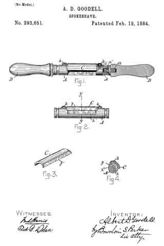
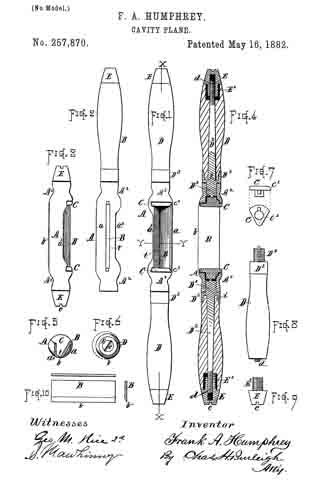
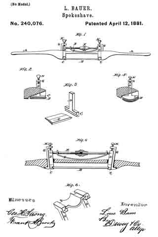
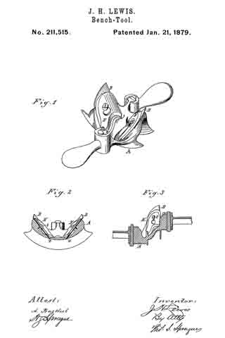
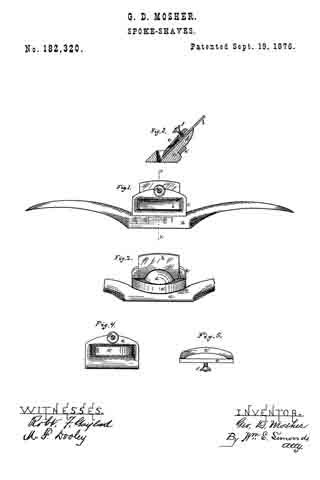
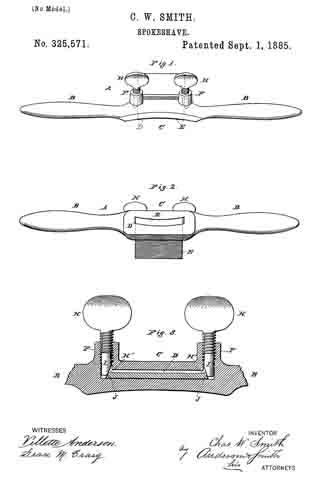
Figure 1 of the drawings is a representation of this invention, and is a front view. Fig. 2 is a view of the under side. Fig. 3 is a longitudinal section taken in line with the set-screws and studs when held vertically.

This invention relates to tool-holders of the class commonly termed “spokeshaves;” and it consists in the construction and novel arrangement of devices, all as hereinafter fully described, and particularly pointed out in the claim.

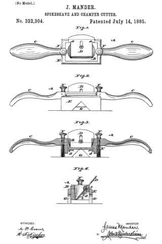
Referring by letter to the accompanying drawings, A designates the tool-handle, having the usual arms, B B. The middle portion, G, of the tool-holder is provided with a throat, D, for the tool or blade E. At each end of the throat D is provided a hollow stud, F, Which communicates at its lower end with the throat D, and is threaded internally in its upper end for the reception of a set-screw, H, a screw, H, being employed in each hollow stud F. The lower portion of each hollow stud is provided with an opening, H’, which conununicates with the throat D of the tool-holder.

In the bottom of each stud F is placed a key, I, the upper end of which is cylindrical in cross section. The keys I I are beveled at one side to cause them, when in proper position in their seats, to bear against the edges of the bits J when the screws H H are turned down upon them to hold the bit K in place in the throat D of the tool-holder, and in the position to which the latter may have been adjusted.

To adjust the bit K the set-screws must be loosened, the bit moved, and the set-screws H H must be again tightened.

This construction is simple, and the parts are positive in their action.

Having thus fully described my invention, what I claim as new, and desire to secure by Letters Patent of the United States, is —

The combination, with the tool-handle having the throat and the hollow studs having threaded upper portions, and the open lower portions communicating with the throat of tool-handle, of the keys I I, provided with longitudinally-beveled faces, and the set-screws for operating the keys to engage the lateral edges of the cutter, substantially as specified.

In testimony whereof I attire my signature in presence of two witnesses.

CHARLES WILLIAM SMITH. [L. S.]

Witnesses:
JOS. W. BRYANT,
WM. H. BRYANT.

No. 322,304 – Spokeshave And Chamfer-Cutter (James Mander) (1885)

[paiddownloads id=”396″]322304


UNITED STATES PATENT OFFICE.

_________________

JAMES MANDER, OF PHILADELPHIA, PENNSYLVANIA, ASSIGNOR OF
ONE-HALF TO MAURICE R. DILLIN, OF SAME PLACE.

SPOKESHAVE AND CHAMFER-CUTTER.

_________________

SPECIFICATION forming part of Letters Patent No. 322,304, dated July 14, 1885.
Application filed January 24, 1885. (No model.)

_________________

To all whom it may concern:

Be it known that I, JAMES MANDER, a subject of the Queen of Great Britain, residing in the city and county of Philadelphia, State of Pennsylvania, have invented a new and useful Improvement in Chamfer-Cutters and Spoke-shaves, which improvement is fully set forth in the following specification and accompanying drawings, in which —

Figure 1 represents a top or plan view of a chamfer-cutter and spokeshave embodying my invention. Fig. 2 represents a side elevation thereof. Fig. 3 represents a longitudinal section thereof. Fig. 4. represents a transverse section thereof.

Similar letters of reference indicate corresponding parts in the several figures.

My invention consists of a tool which is adapted to be used either as a chamfer-cutter or a spokeshave, as will be hereinafter fully set forth.

Referring to the drawings, A represents a spokeshave, consisting of the stock B, handles C, and bit or blade D, the latter being fitted in diagonally-extending grooves a, formed in the inner sides of the stock.

The back of the stock is cut away, as at b, so that the rear face of the bit is supported by the top cross-bar, c, and side lugs, d, whereby the main portion of the back of the bit below said cross-bar, excepting the small portion contiguous to the lugs d, is uncovered or unobstructed, by which provision the bit is adapted for deep cuts and to perform a greater range of work, limited by the top cross-bar, c, instead of the bottom edge of the back of the stock, as in spokeshaves heretofore constructed.

E represents a frame or case, which, open at top and bottom, is adapted to receive the stock of the spokeshave and the contiguous portions of the handles thereof.

Screws F are swiveled to the spokeshave and tapped in the sides of the case E, whereby provision is made for raising and lowering the spokeshave in said box and thus adjust the bit D therein.

In the bottom edges of the front and rear walls of the case E are recesses G of inverted-V shape, the same constituting guides when the tool is used as a chamfer-cutter, it being noticed that the bit of the spokeshave is the bit of such cutter, and the handles C are employed for operating said cutter.

The tool is presented to the wood so that the latter is coincident with the guide-recesses G, and the tool operated, whereby the wood is readily cut with a chamfer, it being noticed that the depth of the chamfer may be varied or adjusted by properly rotating the screws F, and it will also be noticed that as much of the back of the bit is uncovered as has been set forth, the work of chamfering may be accomplished with facility, the back of the stock presenting no obstructions to the cutting action of the bit to the extreme depth of the guide-recesses G.

Another advantage in leaving the back of the bit uncovered in the manner stated is, that the bit is adapted for cutting what are known as “stop-chamfers,” which may be of various depths, and cannot be produced where the bit is covered in spokeshaves heretofore in use.

I am aware that a spokeshave having a blade adjustable in a recessed stock is old, and also that a combined spoke and chamfer cutter is formed with a casing having recesses thereon, and such I do not broadly claim.

Having thus described my invention, what I claim as new, and desire to secure by Letters Patent, is —

1. In a combined chamfer-cutter and spoke-shave, the spokeshave having a recessed stock, in combination with a blade seated in said stock and supported by a cross-bar of the shave, and a case having recesses in both the front and rear walls of an inverted-V shape, substantially as and for the purpose set forth.

2. The stock B, having a cross-bar, c, and side lugs, d, connected therewith, in combination with a blade secured to said cross-bar c, and supported by said lugs, substantially as and for the purpose set forth.

3. In a combined chamfer-cutter and spokeshave, the stock B of the latter, in combination with the blade D, secured to a cross-bar, c, of said stock, and a case, E, having recesses of inverted-V shape in both the front and rear walls thereof, and screws connected with the spokeshave and engaging with said case, substantially as and for the purpose set forth.

JAMES MANDER.

Witnesses:
JOHN A. WIEDERSHEIM,
A. P. GRANT.

No. 294,197 – Spokeshave (Addison E. Chapman) (1884)

[paiddownloads id=”356″]294197


UNITED STATES PATENT OFFICE.

_________________

ADDISON E. CHAPMAN, OF OLEAN, NEW YORK.

SPOKESHAVE.

_________________

SPECIFICATION forming part of Letters Patent No. 294,197, dated February 26, 1884.
Application filed September 11, 1883. (No model.)

_________________

To all whom it may concern:

Be it known that I, ADDISON E. CHAPMAN, a citizen of the United States, residing at Olean, in the county of Cattaraugus and State of New York, have invented a new and useful Improvement in Spokeshaves, of which the following is a specification.

This invention relates to that class of spoke-shaves in which a cast frame or handle is used to carry a blade and fastening devices.

Heretofore the blades of metallic spoke-shaves have usually been clamped in place in the body by means of one or more wedges held by two setscrews, one at each end of the blade. This necessitated the working of two screws to secure the blade or to remove it. It also prevented inserting the spokeshave into holes and thin places on account of the thumb-screws protruding at both edges of the blade.

The object of my invention is to obviate these objections and to provide a fastening device which shall securely hold the blade in place, yet may be quickly loosened to release the blade.

To this end my invention consists in a handle having a recess to receive a blade, and a wedge of peculiar shape, and a screw peculiarly shaped and located therein, as hereinafter described and claimed, reference being had to the accompanying drawings, in which —

Figure 1 is a rear view, Fig. 2 is a top view, and Fig. 3 is a transverse vertical section, of my spokeshave.

A represents the stock of the spokeshave, usually cast metal, formed with an aperture, B, whose lower side, b, is plane or laterally concave, serving as the seat for the blade C.

D is the wedge for holding the blade in place by resting flat upon the top thereof, and being itself held down at its two ends. For this purpose the two ends of said wedge are inclined or wedging in thickness, one end entering under a wedging-ledge, a, of the stock and the other end held by a tapering pointed screw, E. This screw is threaded into the stock A, and being bluntly tapered, its action upon the wedge is threefold. Its first action is to press the wedge against the opposite bearing, a, which being wedging, as stated, begins binding on the blade. As soon as the wedge becomes seated, so that it will no longer slide endwise from the screw, then the continued action of the screw binds the adjacent end thereof down upon the blade, thus firnily securing the same in place. The screw being right-hand threaded and located at the right hand of the blade when the latter faces from you, the revolution of the screw impinging against the end of the wedge has a creeping effect to draw that end of the wedge laterally into the stock. When the motion of the screw is reversed, each effect is reversed, the first tendency being to loosen the wedge and the second to work it out of the stock. Thus the action of each part is in all respects toward the desired end. The stock, blade, and wedge may in other respects be of any desired form. The front side of the wedge will usually be thinned to an edge to turn the shavings from the blade over it through the aperture B. Yet should it be desirable to make the wedge bear only upon the two ends of the blade and raise its middle to allow shavings to pass under, still my means of fastening the same by its ends will answer the same purpose.

I am aware that a spokeshave having its blade held directly by a wedging-edge of the handle or stock at one end, and the blade left unsupported between these resting-points, is not new, and I do not claim the same.

What I claim as my invention, and wish to secure by Letters Patent, is —

The stock of a spokeshave, having an aperture to receive the blade and a bed for the same to rest on throughout its length, and a wedging-ledge at one end of said aperture, in combination with a tapering pointed screw in the stock at the opposite end of said aperture, and a wedge inclined at both ends, as shown and described, whereby a blade may be held, as specified.

ADDISON E. CHAPMAN.

Witnesses:
E. C. CLEVELAND,
ROBERT H. WILBUR.

No. 293,651 – Spokeshave (Albert D. Goodell) (1884)

[paiddownloads id=”352″]293651


UNITED STATES PATENT OFFICE.

_________________

ALBERT D. GOODELL, OF MILLER’S FALLS, MASSACHUSETTS, ASSIGNOR
TO THE MILLERS FALLS COMPANY, OF SAME PLACE.

SPOKESHAVE.

_________________

SPECIFICATION forming part of Letters Patent No. 293,651, dated February 19, 1884.
Application filed November 30, 1883. (No model.)

_________________

To all whom it may concern:

Be it known that I, ALBERT D. GOODELL., residing in Miller’s Falls, in the county of Franklin and State of Massachusetts, a citizen of the United States, have invented a new and useful Improvement in Spokeshaves, of which the following is a full, clear, and exact description, reference being had to the accompanying drawings, forming a part of this specification, and in which like letters indicate corresponding parts.

My invention relates to improvements in spokeshaves, by which, by the use of a circular knife or cutter and other novel features, much better work can be done and a far greater variety of forms of material operated upon the by the use of any existing tool known to me.

Figure 1 represents a general view of the article, having part of the body and one handle cut away to exhibit the threaded screw in the body for holding the cutter, and also the screw by which the handles are detachably connected with the body. Fig. 2 represents the body without the handles, and shows the edge of the circular cutter and the front bevel of the body. Fig. 3 represents the knife or cutter C with beveled edge z. Fig. 4. represents a cross-section of the body, taken at y y, Fig. 2, and illustrates the manner in which the body is cut away, to form the mouth for discharge of the chips or shavings.

A is the body, preferably of metal.

B B are the handles, which are made detachable from the body by means of a screw inserted in the end of the handle, and threaded orifice formed in the end of the body, into which the threaded screw is inserted.

C is the circular knife or cutter, and is secured to the body, which is preferably made of the same circle as the cutter, by the round-headed set-screws b b. Upon the cutting-face of the shave the body is slightly beveled, preferably at a slight angle from the cutting-edge of the circular knife or cutter. This face-bevel is indicated by x’, the body under the knife or cutter being cut away, as shown in section, Fig. 4.

a is the portion of the body not cut out, and as represents the cut-away portion under the knife or cutter, and which forms the mouth for discharge of the chips.

The great difficulty heretofore experienced in tools of this kind I seek to obviate. I form my knife or cutter circular, in order to obtain a clean out instead of a scraping action, so common to most tools for the same purpose. Besides, this form of knife or cutter will not chatter, cannot get caught upon any part of the work, nor upon the clothing of the operator. The finest work can be done without danger of injury to the face of the material, and the ample opening in the body under the knife or cutter prevents clogging and facilitates the freest discharge of chips or shavings.

It will be further observed that I am enabled to securely hold the knife or cutter by the direct action of the round-headed set-screws, and no unnecessary protuberance is placed anywhere upon the tool.

The object of making the handles readily detachable is that in operating upon small work and in a limited space one or both handles can be removed and the work done with ease and facility. I deem this avaluable feature in connection with the form of the body of the tool and the absence of all annoying projections or protuberances upon any part of the surface of the body.

The present tool will work effectively in almost any position and upon either flat or round surfaces.

Having now described my invention so that any person skilled in the art may readily understand its form and mode of operation, what I claim, and desire to secure by Letters Patent of the United States, is —

1. A spokeshave consisting of the body A, removable handles B B, and circular cutter or knife C, and the set-screws b b, adapted to secure in place the cutter or knife C by pressure of the screw-heads upon the edges of the same, substantially as and for the purposes set forth.

2. In a spokeshave, the body A, circular knife C, arranged and secured thereto, so that the chips or shavings pass under said knife to the place of discharge, in combination with detachable handles B, substantially as and for the purposes set forth.

3. In aspokeshave, the circular knife or cutter C, formed with a straight cutting-edge, and adapted to be detachably secured to the body of the shave by suitable means, as and for the purposes set forth.

4. In a spokeshave, the body A, straight circular kniie C, and set-screws b b, adapted to hold the said knife to the body, combined as and for the purposes set forth.

5. The combination of the body A with straight circular knife suitably secured thereto, and the detachable handles B B, substantially as set forth and deseribed.

6. In a spokeshare, the body A, with bevel x’, in combination with the circular knife or cutter C, substantially as and for the purposes described.

7. In a spokeshave, the body A, provided with the rear discliarge-passage, x, in combination with a circular knife or cutter having a straight cutting-edge and suitably secured to said body, substantially as and for the purposes described.

8. A spokeshave provided with a straight circular body adapted to receive a straight circular knife or cutter, and to discharge the chips or shavings under the said knife or cutter and to the rear ofthe working-face, all substantially as and for the purposes set forth.

9. In a spokeshave, the cornbination of the body A, provided with the discharge-opening x, formed by removing a portion of the body, and having a face-bevel, x’, and circular knife formed with a straight cutting-edge and adapted to be detachably secured to the said body, substantially as and for the purposes set forth.

ALBERT D. GOODELL [L. S.]

Witnesses:
F. M. THOMPSON,
L. J. GUNN.

No. 289,459 – Spokeshave (Gary B. Smith) (1883)

[paiddownloads id=”349″]289459


UNITED STATES PATENT OFFICE.

_________________

GARY B. SMITH, OF DENVER, COLORADO, ASSIGNOR TO ROBERT E. PERRY, OF SAME PLACE.

SPOKESHAVE.

_________________

SPECIFICATION forming part of Letters Patent No. 289,459, dated December 4, 1883.
Application filed August 15, 18803. (No model.)

_________________

To all whom it may concern:

Be it known that I, GARY B. SMITH, a citizen of the United States of America, residing at Denver, in the State of Colorado, have invented certain new and useful Improvements in Spokeshaves; and I do hereby declare the following to be a full, clear, and exact description of the invention, such as will enable others skilled in the art to which it appertains to make and use the same.

This invention relates to that class of spoke-shaves having adjustable bevel gage-stops, which serve to gage the spokeshave for chamfering; and the objects of this improvement are to fit the parts composing the bevel gage-stop without the aid of screws and to improve the construction of this class of spokeshaves, whereby the material (wood) can be accurately cut at all the desired angles.

With these and other objects in view my invention consists in a bevel gage-stop for a spokeshave, composed, essentially, of three parts united for angular inclinations. My invention further consists in the novel construction and combination of parts, as will be hereinafter more fully set forth.

In the annexed drawings, Figure 1 is a side view, partially in section, of my improved spokeshave. Fig. 2 is a plan view of the under side of the stock. Fig. 3 is a perspective view of the bevel gage-stop. Fig. 4 is a plan view of the angle-plate. Fig. 5 is a perspective view of the horizontal plate, and Fig. 6 is a plan view of the bar that connects the angle and horizontal plates.

In the manufacture of the spokeshave the stock A is preferably made of malleable iron, and is formed with two parallel grooves, b, extending in the direction of the length of the stock. The continuity of one of these grooves is broken about midway of its length by the throat-slot c, for the reception and passage of the plane-bit d and set-iron with its screw, as seen in Figs. 1 and 2 of the drawings. This stock is also formed at the opposite ends with the longitudinal slots e e, for the reception. and adjustment of the thumb-screws f, connected to the bevel gage-stops, hereinafter described; also, the continuation of the slots into and the enlargement of the same in the ends of the stock will permit of the ready removal of the stops. This is accomplished by loosening the set-screws f a little, then adjusting the stops until the set-screws drop through the enlarged openings. The bevel gage-stop B, as seen in Figs. 1 and 3, is essentially composed of the horizontal plate C, the angular face-plate D, and the diagonal connecting-bar E. The horizontal plate B is formed with two longitudinal tongues, h, arranged to fit and work in the grooves b of the stock. Its inner end is formed with an overlap-joint, i, for attachment to the transverse bar K of the angular face-plate D, and the plate is also formed with a longitudinal slot, in, for the reception of a rectangular or other shaped boss, n, on the upper end of the connecting-bar E. The opposite or lower end of the angular face-plate D is formed with a concave or depression, r, and a slot, s, in the concave part to receive the reduced portion and cross-bart of the connecting-bar, as shown in Figs. 1 and 2 of the drawings. The connecting-bar, in connection with the slot in the horizontal plate and thumb-screw, is for adjusting the inclination of the angular face-plate. By this construction of the members composing the bevel gagestop the parts are readily coupled together without the aid of auxiliary fastening means, and no portion of the connecting means projects beyond the face of the angular plate. The bevel gage-stops are attached to opposite sides of the plane-bit, as seen in Fig. 1 of the drawings, by means of the thumb-screws passed through the slots of the stock and connected to the rear ends of the connecting-bars of the gage-stops. To adjust the gage-stops to or from the plane-bit, or to secure a different angle to the face-plates D, the thumb-screws are loosened and the gage-stops are adjusted as desired, or the inclination of the face-plates set at the required angle, when the thumb-screws are again made secure.

This spokeshave is used substantially in the manner as those of the same class. I wish to reserve the right to vary the construc-
tion and arrangement of parts without departing from the spirt of the invention.

What I claim is —

1. In a spokeshave, the bevel gage-stop composed, essentially, of the slotted horizontal plate, the angular face-plate hinged to the inner end of the horizontal plate, and the adjustable connecting-bar loosely connected to the lower end of the faceplate with a set-screw, substantially as set forth.

2. In a spokeshave, the combination of the horizontal-plate formed at one end with an overlap joint, and the angular face-plate formed with the transverse bar for connection with the overlap-joint of the horizontal plate, whereby a hinge-connection is formed for the relative adjustment of the face-plate, substantially as described.

3. The bevel gage stop for a spokeshave, consisting of the slotted horizontal plate formed with the parallel ribs and overlap-joint, the angular face-plate formed with the transverse bar and the concave or depression, and the connecting-bar formed with the boss and the cross-bar, said members being organized substantially as described.

4. The improved spokeshave consisting, essentially, of the stock; formed with longitndinal slots enlarged at the outer ends, slotted plates with the angular face-plates and connecting-arms, said plates and arms being connected as described, and the thumb-screws, substantially as and for the purposes set forth.

In testimony whereof I affix my signature in presence of two witnesses.

G. B. SMITH.

Witnesses:
JOHN W. WEBSTER,
AUBREY PERRY.

No. 273,073 – Spokeshave (Andre S. Haynes) (1883)

[paiddownloads id=”330″]273073


UNITED STATES PATENT OFFICE.

_________________

ANDRE S. HAYNES, OF ROME, NEW YORK.

SPOKESHAVE.

_________________

SPECIFICATION forming part of Letters Patent No. 273,073, dated February 27, 1883.
Application filed August 15, 1882. (No model.)

_________________

To all whom it may concern:

Be it known that I, ANDRE S. HAYNES, of Rome, in the county of Oneida and State of New York, have invented a new and Improved Combined Spokeshave and Chamfering-Tool, of which the following is a full, clear, and exact description.

My invention consists of the application of bevel gage-stops to a spokeshave in a manner to serve for gaging the spokeshave suitably for chamfering the corners of the work, the said stops being laterally and angularly adjustable for setting them to stop the shave at any required point, according to the amount and angle it is desired to chamfer the work, all as hereinafter fully described.

Reference is to be had to the accompanying drawings, forming part of this specification, in which similar letters of reference indicate corresponding parts in all the figures.

Figure 1 is a plan view of my improved tool. Fig. 2 is partly a side elevation and partly a section on the line x x of Fig. 1. Fig. 3 is a cross-section on the line y y of Fig. 1.

I plane the under side of the stock a each side of the socket c for the plane d in a straight line with the face c, where the plane-bit f projects, and apply thereto the bevel gage-stops g, making them adjustable toward and from each other by bolting them on through slots h by thumb-screws i. The said gage-stops are notched at j to enable them to shift along the projecting plane-bit to set them as close together as the amount it is desired to chamfer the work may demand. The shanks k have bits or studsl at the outer ends, to bear in the grooves in of the spokeshave-stock a, to guard against lateral divergence of the stops by the friction on the work.

The gage-stops may be constructed on angles of forty-five degrees to the plane-bit, as for square work; but they will serve for work of other shapes, for it is not necessary that the faces bear fair upon the sides of the work. If the angle of the work is larger than the angle of the gages, they will bear at the lower edges, and if the said angle be smaller, they will bear at the upper edges.

If desired, different sets of stops may be constructed on different angles for special shapes of work. This arrangement of interchangeable stops with fixed heads or faces g is represented at the right-hand side of Fig. 2; but I make the stop-faces g angularly adjustable by pivoting them to the shank k, as at the left-hand side of Fig. 2, thereby permitting them to be used at one or both sides, and to be adjustable to any angle for chamfering more to one side or face of the work than the other, as will readily be understood.

Having thus fully described my invention, I claim as new and desire to secure by Letters Patent —

1. The combination of bevel gage-stops g with a spokeshave, said stops being adjustable toward and from each other and arranged to act on the opposite sides of the work to gage and stop the cutter on the angle, substantially as described.

2. The gage-stops g, having notch j, arranged with relation to the plane-bit f and said stops being adjustable along said plane-bit, substantially as described.

3. The adjustable gage-stops g, having guide studs l, in combination with the grooved stock a and plane-bit f, substantially as described.

4. The combination of bevel gage-stops g, adjustable toward and from each other with relation to the plane-bit f, and pivoted to their shanks k, to be angularly adjustable to the faces of the work, substantially as and for the purposes set forth.

ANDRE S. HAYNES.

Witnesses:
P. R. HUGGINS,
A. O. HICKS.

No. 270,769 – Cavity-Plane (James England) (1883)

[paiddownloads id=”326″]270769


UNITED STATES PATENT OFFICE.

_________________

JAMES ENGLAND, OF NEW YORK, N. Y.

CAVITY-PLANE.

_________________

SPECIFICATION forming part of Letters Patent No. 270,769, dated January 16, 1883.
Application filed April 29, 1882. (No model.)

_________________

To all whom it may concern:

Be it known that I, JAMES ENGLAND, of the city, county, and State of New York, have invented a new and useful Improvement in Hand Planing and Grooving Tools, of which the following is a full, clear, and exact description.

This invention, which is applicable to various kinds of planing and grooving tools suitable for carpenters, coopers, and other like uses, consists in a double or opposite handle-ended tool provided with an intermediate slotted metal frame and one or more cutter-holders with attached face plate or plates, and rear end projections adjustable within or through said frame and capable of being secured therein at any desired distance from the main or handle portion of the tool, whereby an implement readily convertible into different uses is obtained, and the cutting portion of the tool may be made to work at different distances from the main body of it.

Reference is to be had to the accompanying drawings, forming a part of this specification, in which similar letters of reference indicate corresponding parts in all the figures.

Figure 1 represents a longitudinal side elvation of a reversible or double-faced spoke-shave constructed in accordance with my invention. Fig. 2 is a transverse section of the same on the line x x; and Fig. 3, a plan of a slotted frame attached to or forming part of the handle of said tool, and serving tor the reception or adjustment of a cutter-holding frame, with its attached face plate or plates. Fig. 4 is a vertical longitudinal section on the line y y, Fig. 5, of a planing-cutter frame with attached face-plate of segmental shape and planing-cutter in its place, suitable for insertion and adjustment within the slotted frame of the handle of the tool shown in Fig. 1, in place of the double-faced spoke-shave cutter-frame arranged therein; and Fig. 5 is an inverted plan of the same. Fig. 6 is a side elevation of a grooving-cutter frame with its attached face-plate and cutter, similarly interchangeable with the spoke-shave cutter-frame shown in Fig. 1.

A in the drawings indicates an oblong metal frame, having a longitudinal slot, b, down through it, and having handles A’ A’ attached to its outer ends and guides or ways c c on the interior of its ends. Said metal frame is likewise provided with holding-screws d d on its sides and ends for securing the cutter-holding frame, with its attached face-plate and cutter or cutters, within the slotted frame A.

The tool, taken as a whole, is designed to be used as a spoke-shave, and is so used as far as the grasp and manipulation of it by the handles A’ A’ are concerned ; but the slotted metal frame A, with its screws d d, not only provides for readily converting it into various kinds of planing, grooving, or scraping tools, but also for the adjustment of the face-plate of the tool to different distances from the longitudinal center of the handle-holding portion of it. This latter provision is very advantageous, inasmuch as it admits of the face-plate, and in fact of the whole cutter-holding portion of the tool, being projected more or less beyond the main or handle portion of the tool, to work in recesses or places where it is not convenient or practicable to work the entire implement, and where the tool is a grooving one it may, by the provision which is thus secured for it, be used to cut a deeper groove beyond the general surface of the work than otherwise would be practicable.

To these ends or purposes, which are distinct from the mere adjustment of the cutter or cutters relatively to their face plate or plates, the cutter-holding portion of the tool is distinct from the handle portion of it, and is made adjustable up or down within or through the slotted metal frame A by constructing the face plate or plates B of the implement with end projections, C C, perpendicular to the face-plates, and at a suitable distance apart to be capable of sliding within or through the ends or ways c c of the slotted frame A, and of being secured therein by the screws d d at any desired projection from the handle portion of the instrument to which they may have been adjusted, such face plate or plates B, with their attached projections C C, constituting a cutter-holding frame. It is immaterial whether the implement be a spoke-shave, as shown in Figs. 1 and 3, a circular planing tool, as provided for by the constructions of the cutter-holder shown in Figs. 4 and 5, a grooving-tool, as provided for by the construction represented in Fig. 6, or any other kind of planing, grooving, or scraping tool having either single or double facing-plates. The facilities of adjusting and securing the cutter-holders, regardless of the shape of the cutters e and independent of their adjustment relatively to their face plate or plates, is the same, and the same main or handle portion of the tool may be used for different cutters or their holders, thus virtually making the implement a readily-convertible one for work of different styles or character.

Having thus described my invention, I claim as new and desire to secure by Letters Patent —

The combination with the handles A’ A’, their connecting slotted frame A, and the screws d d, of a cutter-holding frame having one or more face-plates or surfaces, B, and rear end projections, C C, fitted so as to be adjustable within or through the slotted frame A, essentially as described, and for the purposes herein set forth.

JAMES ENGLAND.

Witnesses:
C. SEDGWICK,
B. G. UNDERWOOD.

No. 257,870 – Cavity-Plane (Frank A. Humphrey) (1882)

[paiddownloads id=”319″]257870


UNITED STATES PATENT OFFICE.

_________________

FRANK A. HUMPHREY, OF WORCESTER, MASSACHUSETTS.

CAVITY-PLANE.

_________________

SPECIFICATION forming part of Letters Patent No. 257,870, dated May 16, 1882.
Application filed November 28, 1881. (No model.)

_________________

To all whom it may concern:

Be it known that I, FRANK A. HUMPHREY, of Worcester, in the county of Worcester and State of Massachusetts, have invented certain new and useful Improvements in Cavity-Planes for Pattern-Makers, Wood-Workers, and Others; and I declare the following to be a description of my said invention sufficiently full, clear, and exact to enable others skilled in the art to which it appertains to make and use the same, reference being had to the accompanying drawings, which form a part of this specification.

The object of my present invention is to provide a practical and efficient tool which can be conveniently employed for dressing out small holes and cavities, and for smoothing narrow surfaces located between or near flanges or angles; also, for working out small curves, and for general whittling and planing in positions inaccessible or inconvenient for working with the ordinary tools.

To this end my invention consists in the improved tool illustrated and described, and in the peculiar constructive features and combinations appertaining thereto, and hereinafter specifically claimed.

In the drawings, Figure 1 is a top view of my cavity-plane with full handles in position. Fig. 2 is a bottom view of the same with one of the handles disconnected. Fig. 3 is a front view with both handles shortened or interchanged. Fig. 4 is a longitudinal sectional view at line x x, Fig. 1. Fig. 5 is a transverse sectional view at line y y, Fig. 1. Fig. 6 is an end view. Fig. 7 shows detail of one of the chuck-pieces for locking the blade in position. Fig. 8 shows a side view of the handle separate from the other parts. Fig. 9 is a side view of the convertible handle-tip, and Fig. 10 shows the form of the blade or cutter.

In the construction, A denotes the body or frame, having a rounded back bar, a, and a forward guard-flange, a’, connecting the cylindrical ends or neck-bosses A2, in the manner illustrated.

B indicates the blade or cutter, formed as a straight rectangular plate, sharpened along one edge, b, and without holes or openings of any kind. Said blade is seated and supported on the inner surface of the back bar, a, (which is properly fitted for its reception,) with its sharpened edge b protruding throngh the throat-opening t at the rear of the guard-flange a’, the blade being set at the proper angle and at such distance from the guard a’ as to give a free cutting action when in use. The shavings pass up through the central opening, and are directed backward by the upper edge of the guard a’, which is made to incline inward for that purpose.

C C indicate chuck-pieces for retaining the blade B in position. Said chuck-pieces fit into the recesses of the frame ends, and are provided with bevels c’ at their rear edges, which are forced against the ends of the blade and clamp it securely in position. The blade B can be held securely in position by either one or both of the chuck-pieces C.

D indicates the handles, which are fitted with screw-threaded connecting-studs D’, for screwing into the central openings of the frame ends A2, and against the chuck-pieces C, for serving the double purpose of attachments for the handles and clamp-screws for the blade B.

E indicates short handles or tip-pieces, which are employed as clamp-screws for retaining the blade when it is desired to adapt the tool for use in a narrow space, as in Fig. 3. Said tips or clamp-screws are provided with ends E’ of the same size and pitch as the connecting-studs D’ of the handles, so as to be readily interchangeable therewith. In the present instance the clamp-screws are made to serve as tips for the wood handles D, but, if desired, could be independent parts, the handles being made complete without them. I prefer, however, to construct them as convertible tips in preference to independent set-screws, and I arrange them in combination with the handles as follows:

The tang or shank D2 of the screw-studs D’ is made to extend completely through the wood of the handle, (the ferrule D3 being formed integral therewith, ) and a screw-thread formed on its outer end, d. The end of the wood handle is recessed, and the piece E, which is furnished with a central screw-threaded opening, screws onto said end d of the tang and forms the finishing-tip of the handle when not required for use, as in Fig. 3. The tips E are provided with recesses or nicks e, and small ribs or projections f may be made on the ends of the connecting-studs D’, (see Figs. 4 and 8,) which fit said nicks, so that the handle can be used as a screw-driver for starting or screwing up said tip-pieces on the handle or frame ends.

Lugs i maybe formed under the fcrrnles D3, to prevent the wood handle from turning on the tang D2. The shape of the handles can be modified to adapt the tool for convenient application or use on different classes of work.

The tool can be used with two handles, as in Fig. 1, or with a single handle, (either right or left,) as in Fig. 2, or with only the short body and clamp-screws E, (one or both,) as in Fig.
3, thus permitting of its convenient use in narrow spaces between flanges and ribs. It can also be used for planing out small cavities and holes, and can be successfully used in any hole of sufficient size to admit of its entrance, (see dotted line, Fig. 6,) or from three-fourths of an inch diameter upward, while it can be used for right or left hand whittling on straight or convex surfaces and in small corners and angles. The blade can be quickly and conveniently adjusted to cut thin or rank shavings, as required, and said blade can be worn away to a very narrow strip before it requires renewal of the blade. The tool is of great utility and convenience in pattern-making, cabinet-work, and other branches of wood-working, wherein small cavities and various formed recesses require to be worked and smoothed out.

What I claim as of my invention, and desire to secure by Letters Patent, is —

1. The body or frame formed with cylindrical ends or neck-bosses, connected by the externally-rounded back bar and inwardly-inclined guard-flange, and the straight cutting-blade seated on said back bar, with its sharpened edge protruding through the throat-opening at the rear of said guard-flange, the parts being combined and located in relation to each other and the exterior curvature substantially as shown and described.

2. The combination of the body or frame having the back bar and front guard, the straight blade supported on said back bar, and the chuck-pieces fitted into said frame and pressed against the ends of said blade in direction of its length by a screw or clamping device axially arranged within the ends of the frame, for retaining it in position, substantially as set forth.

3. The combination, substantially as hereinbefore described, of the frame having hollow screw-threaded ends A2, connected to each other by the backbar, a,and guard-flange a’, as shown, the straight cutting- blade B, seated on said back bar, the chuck-pieces C, fitted in recesses of the frame ends and resting with a beveled surface against the ends of said blade, and the detachable handles D, having studs or threaded ends for screwing into said frame ends and against said chuck-pieces, for the purposes set forth.

4. The combination with the detachable handles D and blade supporting frame A, of the convertible tip-pieces E, adapted for use as set-screws for the chuck-pieces when the handles are detached, or as end nuts on said handles, substantially as hereinbefore described.

5. The combination, with the body or frame A, of the handles D, having the screw-threaded end studs, D’, with projection f, ferrule D3, and tang D2, screw-threaded at its outer end d, and the convertible tip-pieces E, with nicks e, as shown and described.

Witness my hand this lst day of June, A. D. 1881.

FRANK A. HUMPHREY.

Witnesses:
CHAS. H. BURLEIGH,
GEO. M. RICE, 2d.

No. 240,076 – Spokeshave (Louis Bauer) (1881)

[paiddownloads id=”312″]240076


UNITED STATES PATENT OFFICE.

_________________

LOUIS BAUER, OF SAN FRANCISCO, CALIFORNIA.

SPOKESHAVE.

_________________

SPECIFICATION forming part of Letters Patent No. 240,076, dated April 12, 1881.
Application filed December 27, 1880. (No model.)

_________________

To all whom it may concern:

Be it known that I, LOUIS BAUER, of the city and county of San Francisco, State of California, have invented an Improved Spoke-shave; and I hereby declare the following to be a full, clear, and exact description thereof.

My invention relates to certain improvements in tools for working wood, leather, and other materials, these tools being known as “spokeshaves.”

My invention consists in a novel method of holding and clamping the blade of the shave in place between two clamping-jaws, so that any style of blade may be held in place and may be adjusted to or from the plate or edge, which serves as a gage.

My invention further consists in a means for setting the blade to or from the gage-plate, so as to regulate the cut, all of which will be more fully explained by reference to the accompanying drawings, in which —

Figure 1 is a view of my tool. Fig. 2 is a transverse section. Fig. 3 is a detail view of the knife and holding-post. Fig. 4 is a longitudinal section. Figs. 5 and 6 are modifications of the cutter.

A is the handle or stock of my tool. This handle may be like the ordinary spokeshave, with two ends, or it may be carried back as a single handle, by which to draw or push the tool. It is fitted in the usual manner near the center, to admit the cutting-blade B.

In the ordinary construction of these tools the blade has two ends or tangs turned up and fitted to enter holes made transversely through the stock.

In my invention the blade B has its ends straight and made with wedge or other shaped edges, so as to be held firmly between suitable jaws, C. These jaws are formed upon the ends of posts D, which extend up through the stock A just at the ends of the cutter or blade.

These posts have their fulcrums in the stock, either by being pivoted in the slot, or they may simply be made a little smaller than the holes through which they pass, so that they may have a side movement or oscillation. Between the upper ends of these posts a bar, E, extends, this bar being formed in two parts with a screw-thread upon one or both, so that by means of a nut, F, in the center it may be lengthened or shortened. When the bar is made longer by turning the nut it forces the upper ends of the posts D apart, thus drawing the lower ends with their jaws together, and clamping the cutter-blade firmly between them. In the present case I have shown one part of the bar E made angular or pinned to one post, so as not to turn. This part has screw-threads upon it, while the other part has a nut to fit these threads, its opposite end turning loosely in its post. By this method of securing the cutter in place it may always be adjusted to or from the gage-plate and its proper distance maintained until it is entirely worn out.

It will be seen that any form of cutting-blade may be secured in this manner, the grooves in the bottom of the posts which receive the ends of the blade being straight or curved, as required.

The distance of the cutter from the stock may be regulated to make a thicker or thinner out by loosening the bar E and moving the posts up or down; but for delicate adjustment I employ a device constructed as follows:

G are posts which pass through the stock behind the posts D, and have their lower ends turned outward, or otherwise secured. Their upper ends are turned at right angles above the posts D, and screws H pass through them, so as to press upon the heads of the posts D. When these screws are turned in one direction they will force the posts D downward and move the blade or cutter away from the stock, thus leaving a wide slot. In order to return the blade and make the slot narrower the screws may be so connected with the posts D as to draw them back; but I have shown a flat curved spring, I, the ends of which are turned up and perforated, so that they slip over the ends of the bar E. The center of the spring presses upon the stock, and when the screws H are turned back the spring will force the posts D and bar E upward, thus drawing the knife or cutter closer to the stock. After the adjustment has been made satisfactorily, the bar E, which was previously loosened, may be again tightened, so as to hold the cutter in place.

The construction here described enables me to use a single stock for a number of cutters, and they maybe worn down to a narrow blade before being cast aside.

This tool is especially valuable for working leather, on account of its delicate and easy adjustment.

Having thus described my invention, what I claim as new, and desire to secure by Letters Patent, is —

1. The stock constructed with the inner curved faces, in combination with the blade or cutter B, having its ends beveled to fit corresponding grooves in the lower ends of the oscillating posts D, said posts having the straining rod or bar E extending between their upper ends, and provided with a nut, F, whereby the cutter may be clamped or released, substantially as herein described.

2. The oscillating posts D, with their straining-bar E fitted to hold the cutter B, as shown, in combination with the posts G, screws H, and spring I, whereby the cutter may be adjusted to or from the stock, substantially as herein described.

In witness whereof I have hereunto set my hand.

LOUIS BAUER.

Witnesses:
S. H. NOURSE,
FRANK A. BROOKS.

No. 213,257 – Improvement In Spoke-Shaves (Charles Spring) (1879)

[paiddownloads id=”302″]213257


UNITED STATES PATENT OFFICE.

_________________

CHARLES SPRING, OF HYDE PARK, MASSACHUSETTS.

IMPROVEMENT IN SPOKE-SHAVES.

_________________

Specification forming part of Letters Patent No. 213,257, dated March 11, 1879; application filed December 14, 1878.

_________________

To all whom it may concern:

Be it known that I, CHARLES SPRING, of Hyde Park, county of Norfolk, State of Massachusetts, have invented an Improvement in Spoke-Shaves, of which the following description, in connection with the accompanying drawings, is a specification.

This invention relates to an improved drawing-knife or shave, it consisting, essentially, of a blade having one or both of its ends shaped to bear at one side of the blade against a seat made upon a handle, and to cooperate with shoulders or projections upon the handle, both when the handle extends from the blade at substantially a right angle from its cutting-edge, as shown in full lines in the accompanying drawings, and also when the handle extends in the direction of the length of the blade, as shown in dotted lines, the said handle and blade in each of its two positions being locked and held by a locking device.

Figure 1 represents, in side elevation, a drawing-knife, constructed in accordance with this invention; Fig. 2, a top view thereof, the left-hand handle being turned to project in the direction of the length of the blade; and Fig. 3, a detail of the upper end of the handle.

The blade a, as herein shown, has its ends b b flattened at its rear side to bear against a flattened portion, c, of the handle d, while the edges 2 3 of the blade, as shown in Fig. 1, are made straight, to bear the edge 2 against the lugs f f, as shown in Fig. 1, when the handle extends from the blade, as represented in full lines, or from the blade in the direction of its width.

The handles herein shown are supposed to be of metal ; but their lower portions, or the parts grasped by the hand, may be of wood, if preferred, and screws g, projecting from the upper ends of the handle at right angles to their length, are extended through holes in the blade, and a nut, h, is then applied to each screw, to securely clamp each end of the blade to each handle.

By employing two lugs, f f, instead of one long rib or shoulder, extended from one to the other side of the handle, a space, 4, is left between the lugs, into which (the nut li being loosened, so as to permit the blade and handle to be somewhat separated) when the handle is turned to occupy the position shown in dotted lines, Fig. 1, or in full lines at the left of Fig. 2, the end of the blade may enter, its edges 2 3 falling into the space 4 between the lugs f f which, as the nut is again turned to press the rear side of the blade against the seat portion c, at the upper end of the handle, causes the lugs f f to act with the screw and nut, and grasp and hold the handle and blade, so that the handle will project therefrom substantially in the direction of its length.

One or both of the handles may be held, as in full or dotted lines, Fig. 1, according to the particular work being done with the knife, or whether the workman is right or left handed.

A drawing- knife with the handle as in dotted lines may easily be used to hew or chip a piece of wood.

It is herein assumed that the handle of a drawing-knife has been fitted to a rounded end of a blade, so as to turn thereon, and project from the blade at right angles to its edge or face or back, the handle in such plan turning on an axis parallel with the length of the blade rather than at right angles thereon, as herein provided for.

It is obvious the screw might be attached to the blade, and be made to project through an opening in the handle; but this plan is not liked as well as its converse. (Shown in Fig. 1.)

The handles, constructed as shown, may be turned just opposite the full-line position of Fig. 1, and then the blade may be pushed with its cutting-edge as in advance.

I denominate the screw and nut as “holding devices.”

I claim —

As an improved article of manufacture, a drawing-knife composed of a blade and a movable handle, provided with a scat portion, c, and bearings or lugs f f, to confine the flattened ends of the blade when the handle projects from the blade in the direction of its width or in the direction of its length, substantially as described.

In testimony whereof I have signed my name to this specification in the presence of two subscribing witnesses.

CHARLES SPRING.

Witnesses:
G. W. GREGORY,
N. E. WHITNEY.

No. 211,515 – Improvement In Bench-Tools (James H. Lewis) (1879)

[paiddownloads id=”297″]211515


UNITED STATES PATENT OFFICE.

_________________

JAMES H. LEWIS, OF DETROIT, MICHIGAN, ASSIGNOR OF ONE-HALF HIS RIGHT TO GEORGE H. STELLWAGEN, OF SAME PLACE.

IMPROVEMENT IN BENCH-TOOLS.

_________________

Specification forming part of Letters Patent No. 211,515, dated January 21, 1879; application filed September 18, 1878.

_________________

To all whom it may concern:

Be it known that I, JAMES H. LEWIS, of Detroit, in the county of Wayne and State of Michigan, have invented an Improvement in Bench-Tools, of which the following is a specification:

The nature of my invention relates to certain new and useful improvements in hand or bench tools of the spokeshave class for working curved moldings, having for its object to so construct the same as to enable the operator to work with the grain of the timber when it reverses in direction, thus avoiding the expense of a second tool of the same configuration.

The invention consists in providing the segment stock or head with two throats and cutters, inclined toward each other, as is more fully hereinafter set forth.

In the drawings, Figure 1 is a perspective view of my device. Fig. 2 is a cross-section of the same; and Fig. 3 is a vertical longitudinal section, showing the relative position of the centers.

In the accompanying drawings, which form a part of this specification, A represents a metal stock or head, being a segment whose face has the cross-section of the molding that is to be produced. a are throats, inclined toward each other, as shown, and in which are secured the cutter-bits B by means of clamp-plates B’ and screws b, or in any other convenient manner. These bits have a contour at the cutting-edge adapted to produce a molding of the desired cross-section, but are designed to out in opposite directions, so that in working a curved molding either bit may be used to cut with the grain when it reverses its direction, as it necessarily does, thus avoiding the necessity of having a pair of such tools for working each pattern of molding, the one having a reverse cut from that of the other.

The handles are made detachable, as shown; but it is evident that the stock may be provided with permanent or stationary handles, if desired.

What I claim as my invention is —

The bench-tool described, consisting of the segmental head A, having the throats a a and the cutters B, secured in opposite directions in said head by the adjustable plates B’ and screw b, substantially as and for the purpose set forth.

JAMES H. LEWIS.

Witnesses:
H. S. SPRAGUE,
A. BARTHEL.

No. 182,320 – Improvement In Spokeshaves (George D. Mosher) (1876)

[paiddownloads id=”268″]182320


UNITED STATES PATENT OFFICE.

_________________

GEORGE D. MOSHER, OF NEW BRITAIN, CONNECTICUT.

IMPROVEMENT IN SPOKESHAVES.

_________________

Specification forming part of Letters Patent No. 182,320, dated September 19, 1876; application filed August 24, 1876.

_________________

To all whom it may concern:

Be it known that I, GEORGE D. MOSHER, of New Britain, in the county of Hartford and State of Connecticut, have invented certain new and useful Improvements pertaining to Spokeshaves, of which the following is a specification, reference being had to the accompanying drawings, where —

Figure 1 is a front view. Fig. 2 is a rear view. Fig. 3 is a sectional view on plane x x. Fig. 4 is a detail fron view of the clamp. Fig. 5 is a top view of same.

The letter a denotes the body of the spoke shave, mortised centrally for the passage of the knife b, which lies on the bed c. From the body a rises the standard d, and its front face is a prolongation of the knife-bed c. The knife is held to place by the clamp e, having a loop, e’, the loop of running around the back of the standard d. A set-screw, f runs through the front of clamp e, and bears on the knife.

The novelty consists in the means just described for holding the knife in place; and the same ideas are applicable to planes and box-scrapers.

I claim as my invention —

The combination of the knife b, the clamp e, having the loop e’, and the standard d, all substantially as described, and for the purpose set forth.

GEORGE D. MOSHER.

Witnesses:
WILLIAM H. MAIN,
CHAUNCEY BECKWITH.

No. 176,151 – Improvement In Spokeshaves (Justus A. Traut And Henry Richards) (1876)

[paiddownloads id=”261″]176151


UNITED STATES PATENT OFFICE.

_________________

JUSTUS A. TRAUT AND HENRY RICHARDS, OF NEW BRITAIN, CONNECTICUT.

IMPROVEMENT IN SPOKESHAVES.

_________________

Specification forming part of Letters Patent No. 176,151, dated April 18, 1876; application filed January 24, 1876.

_________________

To all whom it may concern:

Be it known that we, JUSTUS A. TRAUT and HENRY RICHARDS, of New Britain, county of Hartford, and State of Connecticut, have jointly invented certain new and useful Improvements in Spokeshaves; and to enable others skilled in the art to make the same, we will proceed to describe it, referring to the drawings, in which the same letters of reference refer to like parts in each of the figures.

Our invention consists in forming the stock of a spokeshave in a V shape, and with a cutting-iron in each of the faces, in order that it may be used to cut to or from the operator without the need of reversing it. Also, in the peculiar means of fastening and adjusting the irons, as will be hereinafter more fully shown.

In the accompanying drawings, Figure 1 is a plan view of our invention. Fig. 2 is an edge view. Fig. 3 is a cross-section through the compression dogs and screws. Fig. 4 is a cross-section of the handle.

Similar letters of reference indicate similar parts.

a is the stock, having its cross-section in a V shape, so as to form two working faces. In each face is formed a longitudinal slot, m, through which projects the bit b. The interior of the stock is also conical shaped, so as to form two beds for the bits and hold them at a proper cutting-angle. In order to make a more perfect adjustment of the cutting-irons, they should be beveled on the upper side. c c are compression-dogs, corresponding in shape to the interior of the stock a, so as to bear against the face of the bits. Through the dogs c c are formed orifices d d for the reception of thumb screws h h. These orifices are enlarged in their upper portion, so as to form a shoulder, upon which rests a coil-spring, f through which the thumb-screws pass into screw-threaded orifices i i, formed in the stock directly under the dogs c c. One end of these springs bears against the screw-head, and the other against the shoulder or bottom of the spring-chamber, so that they serve before the screws are tightened to sufficiently compress the dogs against the bits, and thus allow of their adjustment, and remove liability to fall out or be misplaced. The handles are curved upward, and made concave underneath and convex on the upper side.

Having described its construction, what we claim, and desire to secure by Letters Patent, is —

The combination, in a spokeshave, of the stock a, having two faces, cutting-irons b, dogs c c, and clamping set-screws h h, substantially as shown and described.

JUSTUS A. TRAUT. [L. S.] HENRY RICHARDS. [L. S.]

Witnesses:
EDWARD B. WILDER,
JEREMY W. BLISS.

No. 174,399 – Improvement In Spoke-Shaves (Albert A. Wood) (1876)

[paiddownloads id=”258″]174399


UNITED STATES PATENT OFFICE.

_________________

ALBERT A. WOOD, OF MANLIUS, NEW YORK.

IMPROVEMENT IN SPOKE-SHAVES.

_________________

Specification forming part of Letters Patent No. 174,399, dated March 7, 1876; application filed July 31, 1875.

_________________

To all whom it may concern:

Be it known that I, ALBERT A. WOOD, of Manlius, in the county of Onondaga and State of New York, have invented a new and useful Improvement in Spoke-Shaves; and I hereby declare the following to be such a full, clear, and exact description of the same as will enable others skilled in the art to which it pertains to construct the same, reference being had to the accompanying drawings, making a part of this specification, and to the letters of reference marked thereon, similar letters indicating corresponding parts in the different figures.

This invention relates to that class of spoke-shaves commonly used by wheelwrights and joiners, the object being to provide a ready means of adjustment for the cutting-bit, so as to enable it to take a cut of a different thickness without being released from its holding-screws and readjusted; and the invention consists in attaching the cutting-bit to an oscillating plate, which is adjusted by means of a thumb-screw and spring, as will be hereinafter fully set forth, and then specifically pointed out in the claim.

Figure 1 of the drawings is a perspective view of the device complete. Fig. 2 shows the throat of the shave with the bit and its carrying-plate removed. Fig. 3 represents the carrying-plate with grooves and recess for the reception of the spring.

The handle or stock A of the shave is made of metal, and is provided with a throat, B, for the reception of the cutting-bit. Within this throat are two longitudinal projections or ridges, a a, and a third elevation, b, upon which the springs g rests. The plate C, having two depressions, d d, at each side, rests upon the projections a a of the stock, within the throat, upon which it oscillates. It also has secured to it, by the screws e e, a cutting-bit, D. This plate is further provided with a recess, f in which is placed a spring, g, the whole of these parts being retained in their proper positions within the throat of the stock by a thumb-screw, h, which passes through the plate and into the stock.

In operating this tool, the plate C, having the spring g in its proper recess, may be placed within the throat of the stock, and the thumb-screw h inserted, and turned up until the plate finds a bearing upon the stock; the bit D is then placed in position, and secured to the plate G by the screws e e, it being so adjusted that its cutting-edge shall project slightly through the throat, so as to take the thinnest shaving which may at any time be required. In order to increase the bite of the tool, and cause it to cut thicker shavings, it is only necessary to turn the thumb-screw slightly backward, which will allow the spring to throw up the outer end of the plate, which, oscillating upon the projections a a, causes the bit to project to a greater distance from the face of the stock, and consequently to cut a shaving of greater thickness, thus avoiding the necessity of loosening and refastening the cutting-bit at each adjustment thereof.

Having thus described my invention, I claim as new, and desire to secure by Letters Patent, the following:

The adjusting-plate C, provided with the recess f and carrying the cutting-bit D, in combination with the stock A and spring g, substantially as and for the purpose specified.

In testimony that I claim the foregoing I have hereunto affixed my signature this 30th day of July, 1875.

ALBERT A. WOOD. [L. S.]

Witnesses:
N. E. ROBINSON,
GEORGE S. BALLOCH.

No. 137,329 – Improvement In Wood-Scrapers (Henry D. Spickler) (1873)

[paiddownloads id=”209″]137329


UNITED STATES PATENT OFFICE.

_________________

HENRY D. SPICKLER, OF CANTON, OHIO.

IMPROVEMENT IN WOOD-SCRAPERS.

_________________

Specification forming part of Letters Patent No. 137,329, dated April 1, 1873; application filed December 5, 1892.

_________________

To all whom it may concern:

Be it known that I, HENRY D. SPICKLER, of Canton, in the county of Stark and State of Ohio, have invented certain new and useful Improvements in Wood- Scrapers; and that the following is a full, clear, and exact specification thereof, which will enable others skilled in the art to make and use the said invention.

My invention relates to the construction of a tool for scraping and smoothing the surface of wooden implements, such, for instance, as ax-handles, spokes, &c., after they have been worked into the desired shape by means of a lathe or other machinery for accomplishing that object. It consists of a metal frame, having a handle cast or otherwise attached at each end, and having two longitudinal slots, in which are secured knives with scraping-edges, one of a straight and the other of a curved form, which are arranged at such an angle with the bottom faces of the frame, and with their edges at such distances from said bottom faces, as to cause the said knives to act as scrapers on the article to be operated on, when the tool is drawn over said article after the manner of using the ordinary spoke-shave. This scraper is applicable to nearly all the uses to which the common plate scraper is applied, while it is much easier to operate and does better work than the common scraper.

In the accompanying drawing, Figure 1 is a top view of the scraper; Fig. 2, a bottom view of the same 5 Fig. 3, a view of that side of the scraper used for curved surfaces; Fig. 4, a view of the side used for straight surfaces; and Fig. 5, a vertical cross-section of the same.

A is the metal frame, having handles a a cast on it. D and E are knives inserted in slots F F, and having their edges d and e turned forward, like the ordinary scraper, the knife E having a curved lower edge, e, while the edge d of the knife D is straight. The knives D E are held firmly in place by means of the wedges f f driven into holes in the frame, the edges of said knives projecting slightly below the bottom-faces B C of the frame. The slots F F in which the knives are placed are made of a triangular section, to receive the scrapings thrown up by the knives. The base of the frame A is inclined from the middle toward the sides, as shown at B and C, Figs. 2 and 5, the face being also curved longitudinally, to correspond to the shape of the knife E, and adapt it to use on curved surfaces. On applying either knife to a wooden surface, the inclination of the base inclines the knife, so that the angle D d c or E e b formed by the knife with the surface toward whichit is moving will be less than a right angle, the acuteness of the angle depending on the amount of inclination of the base, by which means the scraping or turned-up edges d e of the knives are brought at the proper angle to act on the wood, as will be readily seen.

In using the scraper, the operator draws the tool over the wood with the knife d forward, when he wishes to use the straight cutting-edge, and in the opposite direction when the curved edge e is desired, only one cutting edge being in operation at one time, as will be seen from the form of the cross-section shown in Fig. 5.

I lay no claim to a scraper constructed with a single scraping-knife, as such device has been heretofore shown in Letters Patent granted to F. A., J. H., and D. C. Williams, July 24, 1866, No. 56,651, and I confine my claim to a double scraper, having a straight knife on one side and a curved knife on the other, as herein shown.

What I claim as my invention, and desire to secure by Letters Patent, is —

The double scraper herein described, consisting of a frame, A, with handles a a, in which are secured two knives, D E, with turned or scraping edges d e, said knives being arranged back to back, and on opposite sides of the frame A, and one of said knives, D, having a straight, and the other knife, E, a curved edge, substantially as and for the purpose specified.

As evidence of the foregoing, witness my hand this 4th day of November, A. D. 1872.

HENRY D. SPICKLER.

Witnesses:
JOB ABBOTT,
JENNIE M. GRANT.

No. 124,435 – Improvement In Spoke-Shaves (Jacob Groben) (1872)

[paiddownloads id=”192″]124435


UNITED STATES PATENT OFFICE.

_________________

JACOB GROBEN, OF BUFFALO, NEW YORK, ASSIGNOR TO HIMSELF AND
SAMUEL D. SIKES, OF SAME PLACE.

EMPROVEMENT IN SPOKE-SHAVES.

_________________

Specification forming part of Letters Patent No. 124,435, dated March 12, 1872.

_________________

Specification describing certain Improvements in “Spoke-Shaves,” invented by JACOB GROBEN, of Buffalo, in the county of Erie and State of New York.

Nature of the Invention.

This invention relates to certain improvements in spoke-shaves, and it consists of the combination of certain parts as will hereinafter be set forth.

General Description.

In the drawing, Figure 1 is a back elevation. Fig. 2 is a bottom-plan view. Fig. 3 is a cross-section.

A represents the stock, B the cutter or knife, and C the face-guide. The knife is of a rectangular form, without lugs or ears to hold it; but has, instead, slanting edges, which are chamfered off, and which fit in metal sockets a a’, having slanting-grooves b b’, into which these edges set. These goooves are set slanting toward the front, to prevent the knife from slipping out, but more particularly to allow the knife to be set forward whenever the edge becomes worn or ground down, so that the space between the knife and guide may be kept always at the right adjustment. In order to hold the knife in position after it is set forward, I provide one or both of the sockets a a’ with a slot, c, through which a set-screw passes, by which the sockets can be set a little forward, as may become necessary, to keep the knife in proper place. On the under side of the sockets I form lugs e e, which fasten into the wooden stock by the pressure of the screw. The face-guide C, which graduates the cutting, works up and down in the grooves d d’, formed in the side of the stock A. It is held at any height by means of a single screw, E. By these simple devices the throat can be set at any size, and down to the very smallest space, so that cross-grained stuff can be worked just as well as straight stuff, and prevents the knife “eating ” into the wood.

This device of mine makes a very simple but very durable spoke-shave, only being required that the knife should be renewed occasionally to last a long time. It will adjust to a curved as well as a straight-cutter, and will be excellent for sweep-work.

Claim.

The slotted plates a a’, formed with the lugs e, and inclined grooves b b’, in combination with the knife B, and with the movable face guide-plate C, and its adjusting-screw E, all constructed and operating as set forth.

ln witness whereof I have hereunto signed my name in the presence of two subscribing witnesses.

JACOB GROBEN.

Witnesses:
J. R. DRAKE,
C. N. WOODWARD.

No. 110,168 – Improvement In Spoke-Shaves (George N. Stearns) (1870)

[paiddownloads id=”176″]110168


United States Patent Office.


GEORGE N. STEARNS, OF SYRACUSE, NEW YORK.

Letters Patent No. 110,168, dated December 13, 1870.
_________________

IMPROVEMENT IN SPOKE-SHAVES.

_________________

The Schedule referred to in these Letters Patent and making part of the same.

_________________

To all whom it may concern:

Be it known that I, GEORGE N. STEARNS, of the city of Syracuse, in the county of Onondaga and State of New York, have invented a new and improved Mode of Spoke-Shave; and I do hereby declare that the following is a full, clear, and exact description thereof, reference being had to the accompanying drawings and to the letters of reference marked thereon making a part of this specification, in which —

Figure 1 is a perspective view of the same.
Figure 2 is a sectional view, showing the gauge, one on each side of the knife, and the adjusting-screw inserted in the stock.

This invention relates to a new adjusting spoke-shave.

One object of my invention is in adjusting both sides of the gauge iron; the arms at the same time, thereby presenting a true and even cut the entire length of the knife.

To enable others skilled in the art to make and use my invention, I will proceed to describe its construction and operation.

In the accompanying drawings —

A represents the stock, which may be made any suitable shape or size, and of wood or metal. I prefer to make it in the shape shown in the drawing A, and of metal.

b represents the screw, inserted in the stock A for the adjusting of the gauge e e to and from the knife d.

The gauge e e is fastened to the stock A by the means of two bolts F F at the end of the arms g g.

The knife d is fastened to the stock A by the means of two screws C C, the knife d being stationary.

I am aware that other spoke-shaves have been constructed before my invention in which adjusting-gauges have been used in conjunction with knives, but such gauges and substances were differently arranged from mine, and are liable to many serious objections, which are removed by my arrangernents.

Therefore, I do not claim, broadly, the adjusting-gauge when arranged upon a different principle from that involved by my arrangements.

Having thus described my invention,

What I claim as new, and desire to secure by Letters Patent, is —

The spoke-shave herein described, consisting of stock A, gaugee e, constructed, arranged, and operating substantially as described.

GEO. N. STEARNS.

Witnesses:
A. C. MESSENGER,
HARRY GIFFORD.

No. 98,475 – Improvement In Spoke-Shave (Joshua Davies) (1870)

[paiddownloads id=”161″]98475


United States Patent Office.


JOSHUA DAVIES, OF MUSKEGON, MICHIGAN.

Letters Patent No. 98,475, dated January 4, 1870.
_________________

IMPROVEMENT IN SPOKE-SHAVE.

_________________

The Schedule referred to in these Letters Patent and making part of the same.

_________________

To all whom it may concern:

Be it known that I, JOSHUA DAVIES, of Muskegon, in the county of Muskegon, and State of Michigan, have invented a new and useful Improvement in Spoke-Shaves; and I do declare that the following is a true and accurate description thereof, reference being had to the accompanying drawings, and to the letters of reference marked thereon, and being a part of this specification, in which the drawing is a rear elevation.

The nature of this invention relates to an improvement in that class of wood-working tools, known as spoke-shaves, and consists in constructing the same with an adjustable guide-gauge, so that the tool may be guided to plane square, or any desired angle.

In the drawing —

A represents a spoke-shave, provided with the usual bit B.
C is a pair of lugs, cast on the handle of the spoke-shave, in line with the throat, which extends their length.

Between these lugs is pivoted a guide-gauge, D, which is adjustable so as to direct the cut of the bit at right angles thereto, and to form a polygonal surface, it having a sweep of forty-five degrees for that purpose, and is secured by screw a passing through its quadrant b, into the lug E, which is cast on the spoke-shave, as shown.

What I claim as my invention, and desire to secure by Letters Patent, is —

The spoke-shave A, having cast therewith the lugs E and C, and having pivoted, in the latter, the guide-gauge D, substantially as and for the purpose set forth.

JOSHUA DAVIES.

Witnesses :
H. S. SPRAGUE,
M. VAN ALLEN.

No. 97,802 – Improvement In Spoke-Shave (Joseph A. Perley) (1869)

[paiddownloads id=”157″]97802


United States Patent Office.


JOSEPH A. PERLEY, OF LYNN, MASSACHUSETTS, ASSIGNOR T0 HIMSELF AND WILLIAM H. PERLEY, OF SAME PLACE.

Letters Patent No. 97,802, dated November 14, 1869.
_________________

IMPROVEMENT IN SPOKE-SHAVE.

_________________

The Schedule referred to in these Letters Patent and making part of the same.

_________________

To all persons to whom these presents may come:

Be it known that I, JOSEPH A. PERLEY, of Lynn, of the county of Essex, and State of Massachusetts, have made a new and useful invention, having reference to Spoke and Heel-Shaves; and I do hereby declare the same to be fully described in the following specification, and represented in the accompanying drawings, of which —

Figure 1 is a top view,
Figure 2 a bottom view, and
Figure 3, a transverse section of a heel-shave, as provided with my invention, which consists in the combination and arrangement of a double-edged or duplex knife, two adjustable throat-pieces, and the two handles, the whole being substantially as hereinafter explained, and also as exhibited in the said drawings.

In such drawings —

A A denotes the two handles of the implement.

The duplex knife, shown at B, has two cutting-edges, arranged as shown at b b, it being fastened, by means of screws c c, to the handles A A, so as to form with them a stock.

Each of these handles is shaped or provided with inclined beds d d at its inner part, to receive and give support to the next adjacent ends or parts of two movable bars or throat-pieces, C C, which are fastened to the handles by clamp-screws e e e e, that screw into the throat-pieces, and pass through slots f f f f, made in the handles transversely thereof.

With the double-edged knife, and the handles and two throat-pieces constructed and combined or arranged as represented, one of the knife-edges, with its throat-piece, may be adjusted to make a “fine cut,” and the other knife-edge and throat-piece may be arranged to make a coarser or coarse cut, the same admitting of the implement being used both for paring down, or rough cutting and for finishing a heel, a work usually accomplished heretofore by two separate shaves or implements.

I claim the combination of the two handles, the double-edged knife, and the two throat-pieces, substantially in manner as specified.

JOSEPH A. PERLEY.

Witnesses:
R. H. EDDY,
S. N. PIPER.

No. 73,723 – Improvement In Spoke-Shaves (Seth T. Hutchins) (1868)

[paiddownloads id=”135″]73723


United States Patent Office.


SETH T. HUTCHINS, OF NORTH ANSON, MAINE, ASSIGNOR TO HORACE A.
LATHROP, OF SHARON, MASSACHUSETTS.

Letters Patent No. 73,723, dated January 28, 1868.
_________________

IMPROVEMENT IN SPOKE-SHAVES.

_________________

The Schedule referred to in these Letters Patent and making part of the same.

_________________

TO ALL PERSONS TO WHOM THESE PRESENTS MAY COME:

Be it known that I, SETH T. HUTCHINS, of North Anson, in the county of Somerset, and State of Maine, have invented a new and useful Improvement in Heel or Spoke-Shaves; and I do hereby declare the same to be fully described in the following specification, and represented in the accompanying drawings, of which —

Figure 1 is a. top view,
Figure 2 a bottom view, and
Figure 3 a side elevation of a spoke or heel-shave provided with my improvement.

In carrying out my invention, I not only make the adjustable throat-piece or gauge separate from two buttresses, so applied to the stock as to be capable of being moved or adjusted thereon, in order to properly adjust the throat-piece relatively to the knife or cutter, but I hinge the throat-piece to one of the said buttresses in a manner to enable the throat-piece to be turned aside or away from the knife, in order to allow the latter to be sharpened, as occasion may require; the adjusting abutments of the throat-piece remaining in the mean while undisturbed in their positions relatively to the stock. After the sharpening of the knife may have been effected, the restoration of the throat-piece to place against the abutment, away from which it was moved, can be accomplished, by simply turning the throat-piece down thereupon.

In the drawings, A denotes the stock, made in the usual form, and having two handles a a. B is the knife or cutter, fastened in or to the stock, C is the gauge, and D E its two adjustable abutments, each of the latter being held to the stock by means of a clamp-screw, b, going through a slot made in such abutment; the same being so as to enable the distance of the gauge or throat-piece C from the cutting-edge ofthe knife to be either increased or diminished, as circumstances may require. The gauge C is hinged, at or near one extremity, to the abutment E, and at its other end it bears against the other abutment, which is formed with a shoulder or bearing-surface for the gauge to rest on. This application of the gauge enables it to be moved from the abutment D into the position denoted by the dotted lines at G’ in fig. 3.

I do not claim merely applying the gauge to the stock, so as to be adjustable or capable of being adjusted nearer to or further from the knife, in order to either increase or diminish the chip-throat or passage between the knife and the gauge; but

1. I do claim the combination of the separate abutments D E, applied to the stock A, so as to be adjustable, in manner as described, with the gauge C hinged to one of such abutments, and being separate from the other, and to operate with respect to it substantially as explained.

2. I also claim the application of the gauge to its adjusting-devices, so as to be removable from them or either of them, and the knife, when the means of the adjustment of the gauge is held stationary relatively to the stock, as described.

SETH T. HUTCHINS.

Witnesses :
R. H. EDDY,
SAMUEL N. PIPER.