No. 55,599 – Improvement In Spokeshaves (Leonard Bailey) (1866)

[paiddownloads id=”118″]55599


UNITED STATES PATENT OFFICE.

_________________

LEONARD BAILEY, OF BOSTON, MASSACHUSETTS.

IMPROVEMENT IN SPOKESHAVES.

_________________

Specification forming part of Letters Patent No. 55,599, dated June 19, 1866.

_________________

To all whom it may concern:

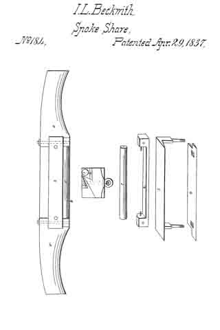
Be it known that I, LEONARD BAILEY, of Boston, in the county of Suffolk and State of Massachusetts, have invented an Improved Spokeshave; and I do hereby declare the same to be fully described in the following specification, and represented in the accompanying drawings, of which —

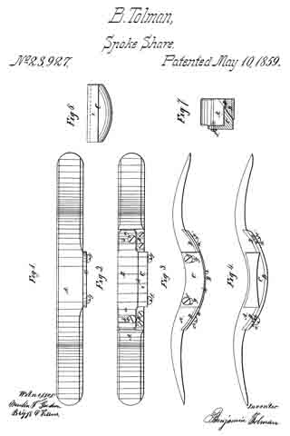
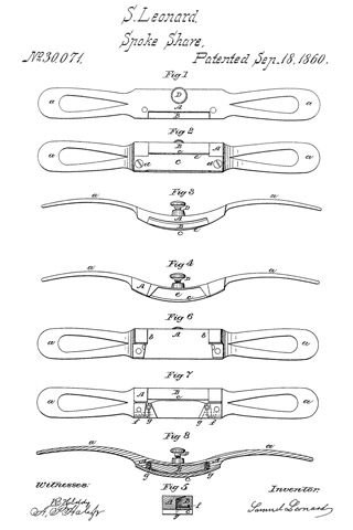
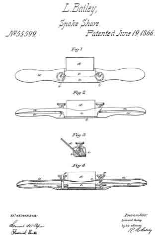
Figure 1 denotes a top view, Fig. 2 a front elevation, Fi g. 3 a transverse section, and Fig. 4 a longitudinal section, of it.

In carrying out my invention I construct the stock of the spokeshave in two separate parts. and so that each of its handles shall be divided into two parts length wise, in manner as shown at a a’ in Figs. 1, 2, and 4. The two lowermost parts, a’ a’, of the handles I combine in one piece with the cutter rest or supporter — that is, so as to extend in opposite directions therefrom — and I also combine the other two or upper parts, a a, of the handles with the adjustable shank-piece c, so as to be in one piece therewith and to extend in opposite directions from it, in manner as exhibited in the figures.

The cutter or shave iron d, resting on the part b, I secure thereto by means of a clamp-bar, e, which is arranged on the cutter and directly over the part b, and is held in place (and so as to conbine the cutter to the said part D) by means of two screws, f f, which go through the lower parts of the handles and screw through the said clamp-bar e, each of such screws being arranged at right angles, or thereabout, with the lower or bearing surface of the part b.

Furthermore, the clamp-bar is caused, near its ends, to abut against two shoulders, i i, formed in or on the stock. These shoulders are arranged in front of the clamp-bar, and not only serve to prevent the downward strain of the screws from breaking the said screws, but co-operate with the screws in setting the bar closely against the cutter or shave-iron, so as to confine it firmly to its bed.

The parts a a touch the parts a’ a’ simply at or near their extremities, the same being in order that such parts a a, with the extension portion c, may constitute a bow or curved spring, to raise the said portion relatively to the cutter, and so as to increase the throat of the implement.

The screws f f are to extend through the parts a a, and screw into nuts g g, so applied to them as to act against the said parts a a, the said nuts and screws serving to effect a counter-movement of the part c, for the purpose of disconnecting the throat of the spoke shave.

The arrangement of the screws f f, the shoulders i i, and the clamp-bar e relatively to the cutter or iron d, the bed on which it rests, and the bottom, surface of the part b renders the clamp very efficient in holding the cutter down to the bed, however the clamp, by the action of the screws, is driven downward in a direction which is at an obtuse angle, its surface in contact with the plane-iron. The screws f f, by their arrangeinent, perform the duty not only of holding the clamp down upon the plane iron, but of co-operating with their nuts in springing the upper parts, a a, ot the handle, so as to regulate the distance of the throat-piece c from the plane-iron.

What I claim in the above improved spoke-shave is as follows:

1. The combination of the screws f f and nuts g g, or their equivalents, with the clamp-bar e, and with the stock divided length wise into two parts or portions, constructed substantially in manner and so as to operate as described.

2 The arrangement of the clamp-bar e with the screws f f and nuts g g, and with the stock divided lengthwise into two parts or portions, constructed substantially in manner and so as to operate with the said screws and nuts, substantially as set forth.

3. The combination and arrangement of the shoulders i i with the screws f f, the clamp-bar e, the cutter d, and bed b, or the stock, substantially as set forth.

LEONARD BAILEY.

Witnesses:
R. H. EDDY,
FREDERICK CURTIS.

No. 20,459 – Spokeshave (Charles H. Weston) (1858)

[paiddownloads id=”74″]20459


UNITED STATES PATENT OFFICE.

_________________

C. H. WESTON, OF NASHUA, NEW HAMPSHIRE.

SPOKESHAVE.

_________________

Specification of Letters Patent No. 20,459, dated June 1, 1858.

_________________

To all whom it may concern:

Be it known that I, C. H. WESTON, of Nashua, in the county of Hillsboro and State of New Harnpshire, have invented a new and useful Spokeshave; and I do hereby declare that the following is a full, clear, and exact description of the constriiction and operation of the same, reference being had to the accompanying drawings, forming a part of this specification, in which —

Figure 1, is a perspective view of the shave in readiness for operation, Fig. 2, is a view of the cap or holder; and Fig. 3, is a section of the handle with the cap and cutter removed.

Similar parts are indicated by the same letters in all the figures.

The nature of my invention consists, first, in confining the cutter by means of a thumb-screw and a single metal plate so constructed as to operate both as a lever-cap and holder; second, in making said cap, or holder, adjustable so as to work in combination with the cutter, when desired, as the top-iron of a double-iron plane; and third, in providing the handle with concave projections on either side of the cutter, to serve as rests for the fingers of the operator, when shoving the instrument from him.

To enable others, skilled in the art, to rnake and use my invention, I will new describe its construction and operation.

A A, Fig. 1, is a metallic handle, cast in one piece, and of any convenient size, like those in common use; D (Fig. 3) being the opening for the reception of the cutter and delivery of shavings.

B a, thin plate of metal, (a top view of which is given in Fig. 2) the underside being a little concave, and the lower edge beveled like that of a plane iron.

b b are arms projecting each side of B, the top sides of which (see Fig. 2) are furnished with little pins, or knobs, e, e.

a a are projecting arms, the under sides of which serve as fulcrums for the arms, b b, of the plate B.

1, 2, and 1, 2, are small holes (see Fig. 3) in the arms, a, a, into which the pins, or knobs, e, e, fit. When e e are placed in holes, 1, 1, the lower edge of plate, B, is carried down so near to the cutter. C, as to answer for the upper iron of a. double-iron plane, or shave, and when in 2, 2, it operates as simply a cap and holder.

G is a thumb-screw passing through a female screw in the plate B, until its point bears on the center, C, — which (as is evident from Fig. 1) will bring the arms b, b, against the fulcrum arms, a a, and the lower edge of B against the lower part of the cutter, C; by which means the cutter can be quickly and securely fastened.

d d are the concave projections in the frame, on both sides of the cutter (as seen in Fig. 1) to serve as rests for the fingers of the operator when shoving the instrument from him.

By loosening the thumb-screw, G, the cuttter can readily be adjusted so as to take any thickness of shaving, or be removed in order to be sharpened.

The method in which the shave can be used either as a single, or double-iron shave, at pleasure, by means of the adjustable cap, or holder B, has been explained above.

What I claim as my invention and desire to secure by Letters Patent, is

1. The plate, B, provided with arms, b, b so as to operate, substantially as set forth in conibination with the fulcrum arms, a, a, and thumb-screw G and projections d d, both as a cap and holder to the cutter, C.

2. Making the cap or holder, B, adjustable by means of knobs, e e, and holes, 1 2, or their equivalents, so that it may operate either as a simple cap and holder to the cutter, C, or in combination with it, as the upper iron of a double-iron plane, substantially as described.

CHARLES H. WESTON.

Winesses:
N. AMES,
O. C. SLEEPER.

No. 20,855 – Spoke Shave (Leonard Bailey) (1858)

[paiddownloads id=”77″]20855


UNITED STATES PATENT OFFICE.

_________________

L. BAILEY, OF WINCHESTER, MASSACHUSETTS.

SPOKE-SHAVE.

_________________

Specification of Letters Patent No. 20,855, dated july 13, 1858.

_________________

To all whom it may concern:

Be it known that I, LEONARD BAILEY, of Winchester, in the county of Middlesex and State of Massachusetts, have invented an Improved Spoke-Shave; and I do hereby declare that the same is fully described and represented in the following specification and the accompanying drawings, of which —

Figure 1, is a top view. Fig. 2, a bottom or underside view, and Fig. 3, a vertical central and transverse section of it. Fig. 4, is a. longitudinal section taken through the retracting spring and its protecting cavity or chamber. Fig. 5, is a top view of the stock without its appliances. Fig. 6, is an end view of the spoke shave.

The nature of my invention consists in an improved spoke shave constructed with its bearing surface in front of its cutter applied to the stock by means of a lever having an adjusting screw or its equivalent or an adjusting screw and a retracting spring so applied to it as to enable the said bearing surface to be moved either toward or away from the cutting edge of the cutter in order to diminish or enlarge the chip passage as well as to vary the angular position of the said bearing surface with respect to that in rear of the cutter, whereby advantages in the operation of the instrument are attained. Also, in an application and arrangement of a protecting cavity or chamber with respect to the lever and its retracting spring.

In the drawing A, denotes the body or the stock of the spoke shave, as constructed with two handles, a, a, and a throat or recess, B, for the reception of a cutter or plane iron B’, which is arranged on the seat or bottom of the throat and is confined thereto by means of a screw, c, which passes through a slot, d, formed in the iron and screws into the stock. The head of the screw laps over the edges of the slot.

The bearing surface of the stock is composed, not only of a stationary part, d’, in rear of the cutter B’, but a movable part, e, which is arranged in front of the cutter. This movable part is made on a lever C, which is shaped as shown in the drawings, and has a journal extending from each side of it, into the adjacent side of the throat such journal being shown in dotted lines in Fig. 1. Furthermore an adjusting screw, E, screws through the back part of the lever and against the seat of the throat of the stock or such screw may pass through the lever and screw into the stock and be so applied to the lever or have such shoulders or appliances that when the screw is turned in one direction it shall tilt the rear part of the lever one way or toward the stock, and when moved in the opposite direction produce a reverse movement of the said lever.

I prefer that the adjusting screw on one side of the journal should screw through the lever and against the seat and that the part of the lever which is on the opposite side of the journals should be provided with a retracting spring I, to be fastened to it and bear on the stock. Were this spring fastened at its middle to the top of the lever and made to extend across the same in such manner as to have its ends bear on the stock, the spring would be so exposed to shavings, as they might be expelled from the throat, that they would be liable to collect between it and the lever and by so doing effect, more or less, its correct action. In order to prevent this I form within and traversely through the lever, a cavity or chamber, g, which I make of a less diameter at its middle part, than it is at its ends or as shown in Fig. 4. This cavity or chamber receives the spring I, made of a piece of round steel wire, and to fit tightly at its middle part to the middle part of the cavity while the ends of the said spring rest on the stock as shown in Figs. 1 and 6. By means of the chamber or cavity surrounding the spring, the latter is protected from shavings which during the use of the shave might rise out of the throat and get between the spring and the lever were the spring not so protected.

By means of the above described mode of changing the width of the mouth of the shave, the thickness of its cut or of the shaving made by it when in use may be regulated, a spoke shave so made being found to operate in practice to great advantage.

I claim —

1. The improved spoke shave as constructed with its bearing surface in front of its cutter, applied to the stock by means of a lever having an adjusting screw or its equivalent, or a screw and a spring applied to it so as to enable the said bearing surface to be moved with respect to the cutter, and the bearing surface in rear thereof, substantially in manner as described.

2. I also claim the arrangement and application of a projecting cavity or chamber within the lever and to the spring thereof in manner and for the purpose as hereinbefore set forth.

In testimony whereof I have hereunto set my signature.

LEONARD BAILEY

Witnesses:
R. H. EDDY,
F. P. HALE, Jr.

No. 23,927 – Spoke Shave (Benjamin Tolman) (1859)

[paiddownloads id=”81″]23927


UNITED STATES PATENT OFFICE.

_________________

BENJN. TOLMAN, OF PEMBROKE, MASSACHUSETTS, ASSIGNOR TO HIMSELF AND A. T. RAMSDELL, OF SAME PLACE.

SPOKE-SHAVE.

_________________

Specification of Letters Patent No. 23,927, dated May 10, 1859.

_________________

To all whom it may concern:

Be it known that I, BENJAMIN TOLMAN, of Pembroke, in the county of Plymouth and State of Massachusetts, have invented an Improved Spoke-Shave or Heel-Shave; and I do hereby declare that the same is fully described and represented in the following specification and the accompanying drawings, of which —

Figure 1, denotes a top view of it. Fig. 2, an underside view of it. Fig. 3, a front side view of it. Fig. 4, a rear side view of it. Fig. 5, a transverse and central section of it. Fig. 6, an underside view of its adjustable throat gage to be hereinafter described.

In the drawings, A, exhibits the stock or handle of the shave; B, the curved knife, while C, is the throat gage, the said knife and throat gage being constructed of metal. In spoke shaves or heel shaves as ordinarily constructed, the knife is furnished with “starts” or adjusting contrivances, which extend transversely through the handle, and cause the knife during the process of adjusting it, to be moved either toward or away from the stock. In consequence of this mode of arranging the adjustments, the knife, while the shave is being used, is very apt to be moved toward the stock or get out of place, for the great pressure employed to keep the tool in contact with the article to be shaved is borne mostly and directly by the knife and in such manner as to render the knife liable to be forced up to or toward the handle. In the construction of my improved shave I have avoided this liability of derangement of the knife. The two ears, a, a, of the knife, are not provided with starts to extend through the handle, but are formed so as to rest with broad bearings or surfaces upon flat surfaces or plates of metal, D, D, screwed or fastened lirmly to the stock, each of the said ears being provided with a slot, b, arranged transversely in it, and for the reception of one of two clamp screws, c, c, which is passed through it and screwed into the bearing plate, such clamp screw having its head projecting over the opposite sides of the slot in order that when screwed down firmly it shall confine the ear in place on the bearing piece. In connection with the said movabllie and adjustable knife, I employ an adjustable throat gage, C, which is formed as shown in the drawings, is fastened by screws f, f, to the front side of the stock. It also extends in front of the knife and between the latter and the stock, as shown in Fig. 5. The screws, f, f, pass respectively through elogated slots g, g, made in the adjustable gage C, the same being so arranged as to enable the gage C, to be moved in a direction at a right angle to that in which the knife is capable of being moved.

The object of adjusting the knife as described is to enable the cutting edge h, to be brought into a suitable position with respect to the rear edge of the bearing part, i, of the throat gage, for it will be observed that in proportion as the knife is worn down by the act of sharpening or grinding it, it will require to be moved forward. Furthermore, the object of making the throat gage adjustable is, to regulate the depth of cut or thickness of shaving to be taken by the knife.

From the above, it will be seen that the knife having been once adjusted and clamped firmly on its bearing plates cannot easily be thrown out of place while in operation, and besides this the adjustment of the distance between the knife and the throat gage can be made without disturbing the knife. As most of the pressure by which the tool is borne against an article while in the act of cutting the same, is borne by the knife, there is little or no danger of derangement of the throat gage.

I do not claim a shave made with a stationary knife and an adjustable gage; nor do I claim a shave as made with an adjustable knife and a stationary mouthpiece disposed in front of the knife, but what I do claim as my invention is —

An improved spoke shave, constructed substantially as herein before described, that is with an adjustable knife and an adjustable throat gage, arranged and applied to the stock, and so as to move with respect to one another as specined.

In testimony whereof I have hereunto set my signature this twenty eighth day of September, A. D. 1857.

BENJAMIN TOLMAN.

Witnesses:
ISAAC JOSLYN,
EVA LAMBERT.

No. 30,071 – Spoke Shave (Samuel Leonard) (1860)

[paiddownloads id=”89″]30071


UNITED STATES PATENT OFFICE.

_________________

SAMUEL LEONARD, OF BRIDGEWATER, MASSACHUSETTS.

SPOKE-SHAVE.

_________________

Specification of Letters Patent No. 30,071, dated September 18, 1860.

_________________

To all whom it may concern:

Be it known that I, SAMUEL LEONARD, of Bridgewater, in the county of Plymouth and State of Massachusetts, have invented a new and useful Improvement in the Spoke-Shave, and do hereby declare that the same is fully described and represented in the following specification and the accompanying drawings, of which —

Figure 1 is a top view; Fig. 2, an under-side view; Fig. 3, a front elevation; Fig. 4, a rear elevation; and Fig. 5, a central and transverse section of a spokeshave containing my invention. Fig. 6 is an underside view of the stock divested of the cutter and its movable throat piece. Fig. 7 is an underside view of the throat piece and the stock as they appear when the knife is removed therefrom. Fig. 8 is a longitudinal section of the instrument taken through the springs of the throat piece.

The nature of my invention consists in an improved arrangement of the adjustable mouthpiece and its operative mechanism with respect to the stock and the cutter arranged in the stock in manner as hereinafter explained.

In the drawings, A, exhibits the stock as provided with two handles, a, a, and as constructed with a recess b, for the reception of an adjustable throat piece B, the recess and throat piece being arranged in the underside of the stock as shown in the drawings. The knife or cutter C extends longitudinally over the throat piece and in rear of its bearing face c, and is fastened at its two ends to the stock by screws, d, d. A chip throat or passage, e, is formed between the knife and the adjustable throat piece B, such chip throat or pqssage e, being made to open or have its discharging mouth at the back of the spoke shave as shown in the drawings. Near the two rearmost corners of the adjustable throat piece B, it is provided with two pivots or journals,f, f, which extend into bearings or pivot holes made in the stock and so as to enable the throat piece to be moved either toward or away from the cutting edge of the knife, its movement toward the said edge being effected by an adjusting screw, D, extending through the front part of the middle of the stock and against the throat piece, B, as shown in the drawings. Furthermore, springs, g, g, are arranged between the throat piece and the knife and near to opposite ends of the throat such springs operating to produce a counter movement of the adjustable throat.

I do not claim any improvement or any arrangement of parts as represented or as claimed in the United States Patent, No. 20855, for although I employ an adjustable bearing surface in front of the cutter and apply the same to the stock by means of a lever actuated by an adjusting screw, my invention consists in an improved arrangement and by means of it and with reference to the spoke-shave described in the said patent, I am enabled to dispense with a stock bearing surface, separate from the cutter or knife and arranged in rear thereof, and make the cutter itself or the lower surface thereof a bearing surface, and furthermore, the discharging mouth of the chip throat of my improved spoke shave is left free or has nothing in rear of it to obstruct the escape of shavings. In this way, while I gain all the advantages of the common spokeshave having no bearing in rear of its knife I also secure that of an adjustable throat and a bearing in front of the knife. Furthermore, I so arrange the space between the said throat piece and the stock, that no shaving passing into the throat can easily get between the said throat piece and the stock so as to clog the operation of the throat piece or prevent it from being moved by its adjusting screw.

I claim —

My improved arrangement of the adjustable mouthpiece and its operative mechanism with respect to the stock and the cutter
arranged in the stock as specified.

SAMUEL LEONARD.

Witnesses:
LAFAYETTE KEITH,
GEO. L. GATES.

No. 32,617 – Spokeshave (Martin Colton) (1861)

[paiddownloads id=”92″]32617


UNITED STATES PATENT OFFICE.

_________________

MARTIN COLTON, OF SARDINIA, NEW YORK.

SPOKESHAVE.

_________________

Specification of Letters Patent No. 32,617, dated June 25, 1861.

_________________

To all whom it may concern:

Be it known that I, MARTIN COLTON, of Sardinia, county of Erie, and State of New York, have invented certain new and useful Improvements in Spokeshaves; and I do hereby declare that the following is a full, clear, and exact description thereof, reference being had to the accompanying drawings, and the letters of reference rnarked thereon, in Which —

Figure I is a bottom plan of my improvement. Fig. II is a cross section on line c–d and Fig. III is a cross section on line a–b. Letters of like name and kind refer to like parts in each of the figures.

The nature of my invention relates to the connection of an adjustable cam face to the stock of the shave in such relative arrangement to the cutting knife that by its adjustment the knife will cut in any required curve.

A, represents the stock of the shave of ordinary construction. B, represents the cutting knife connected to the stock in the cornmon manner.

C, represents the adjustable cam face in length a little longer than the cutting edge of the knife — say one inch at each end — and fitting into a concave recess or chamber made in the stock to receive it. The form of the face on the side nearest the knife and connnencing at the edge of the knife and extending about two thirds of the entire circulnference of the face — is cylindrical. That part of the cam face which bears upon the work has an expanding curvature commencing at the edge of the knife and tangent to the cylindrical part. A journal is formed at each end of the cam face upon the center line of the cylindrical part. These journals turn in eyes (D) which have long shanks (E) passing through the stock and having tightening nuts (F) upon their ends. By turning these nuts the cylindrical part of the cam face llltty be drawn into the recess in the stock and held tightly in any desired position.

In consequence of the expanding curvature of the cam face by loosening the nuts If and turning it upon its journals the distance of the line of bearing upon the work from the cutting edge of the knife may be increased or diininished — increasing it will adapt it to smoothing or cutting surfaces of greater curvature and diminishing it will adapt it to surfaces of less curvature. I am thus able to adapt the shave as required by the peculiarities of the work being done and am enabled to do the work in the most perfect manner.

I claim —

The combination of the adjustable cam face C with the stock A and knife B arranged and operating for the purposes and substantially as set forth.

MARTN COLTON.

Witnesses:
R. SIMON,
SARDIS HOBART.

No. 40,437 – Spokeshave (Melzer Tuell) (1863)

[paiddownloads id=”98″]40437


UNITED STATES PATENT OFFICE.

_________________

MELZER TUELL, OF PENN YAN, NEW YORK.

SPOKESHAVE.

_________________

Specification forming part of Letters Patent No. 40,437, dated October 27, 1863.

_________________

To all whom it may concern:

Be it known that I, MELZER TUELL, of Penn Yan, in the county of Yates and State of New York, have invented a new and useful Improvement in Spokeshaves; and I do hereby declare that the following is a full, clear, and exact description of the construction and operation of the same, reference being had to the annexed drawings, making a part of this specification, in which —

Figure 1 is a bird’s-eye view. Fig. 2 is of the under side. Fig. 3 isa transverse vertical section.

The letters of reference refer to the same parts in each figure.

A is the stock. It is made with an opening or passage for the chips or shavings to pass up through while using it, and it has a handle at each end. The stock is made so that the cutter B and gage C may be fastened to it, as hereinafter described. The center of the stock, center of the cutter, and center of the gage are in the same lines, or both sides of the center are alike, so that the instrument will cut when pushed from or pulled toward the operator, or either end may be taken in the right hand and the result the same. At the under side of the stock, and in the middle and near each end of the opening, is a place fitted to receive the cutter, so that it may be held by bolts or screws that pass through both stock and cutter. The cutter must be far enough below the surface of the stock to admit the regulator above the edges of the cutter. This is done by making projections upon which the knife is fitted for.

The handles are made in line with the cutter, but may be curved up or down, as desired.

At the under side of the stock is placed the adjustable gage C. It is made the width, outside, as the stock, with an opening through it as long as and a little wider than the cutter, so that it will surround the cutter. It is held to the stock by means of pivots F and F, that pass through the projections E and E at the under side of the stock, and through holes in the ends of the gage, as represented in Fig. 2; or the pivot may be made to enter holes made in the ends of the cutter. The gage must be made so as to be easily moved upon the pivots, so that either side of the gage may be raised above the edge of the cutter to admit the edges of the cutter to take the thickness of chip required, so that the more the gage rotates the thicker will be the chip. This motion of the gage is governed by the set-screws D and D. These screws are put through the sides of the stock, as represented in Figs. 1 and 3. By these screws the thickness of the chip is regulated. Wlien the screws are turned back-ward,the chip will be thicker, and when turned forward the regulator has less motion and consequently the cutter cuts a thinner chip.

I do not limit myself to any particular curve, (up or down,) but make them any curve to suit any kind of work, and when any curve of cutter is required the stock and gage must be made to correspond with it. The cutter is made with two opposite cutting-edges, with a hole at each end for bolts or screws that hold it to the stock. To use my invention, first find by trial the thickness of chip. If too thick or too thin, regulate by the screws D D, which is best performed by regulating one side at a time, and when both sides are regulated take one handle in each hand and place the under side of the instrument upon the work and either push it from or pull it toward you, which will cause the instrument to do the work required. This motion will cause the gage to raise to the screws D D one side at a time and allow the edge of the cutter to take hold of the work. Thus each edge of the cutter will take hold of the wood; but both edges will not cut at the same time, but the instrument willwork either way, as the grain of the wood requires.

What I claim, and desire to secure by Letters Patent, is —

1. The stock A and cutter B, when constructed and arranged as and for the purpose Set forth.

2. The adjustable gage C, when made and used as specified.

MELZER TUELL.

Witnesses:

I. SLOAN,
CHARLES KETCHUM.

No. 51,339 – Improvement In Spokeshaves (Silas S. Mowry And Albert G. Bates) (1865)

No. 51,339 – Improvement In Spokeshaves (Silas S. Mowry And Albert G. Bates) (1865)

[paiddownloads id=”111″]51339


UNITED STATES PATENT OFFICE.

_________________

SILAS S. MOWRY AND ALBERT G. BATES, OF PROVIDENCE, RHODE ISLAND.

IMPROVEMENT IN SPOKESHAVES.

_________________

Specification forming part of Letters Patent No. 51,339, dated December 5, 1865.

_________________

To all whom it may concern:

Be it known that we, SILAS S. MOWRY and ALBERT G. BATES, both of the city and county of Providence, in the State of Rhode Island, have invented a new and useful Improveinent in Spokeshavers; and we do hereby declare that the following specification, taken in connection with the drawings, making a part of the same, is a full, clear, and exact description thereof.

Figure 1 is a perspective view. Fig. 2 is a transverse section.

Our improvement has reference to a means for readily adjusting or removing the cutter, so that without loss of time the same can be removed to be sharpened, and be readjusted in place, While at the same time the advantage is secured of being able to make use of the plane-iron so long as there is enough of it left to be held in the stock.

In the accompanying drawings, A, Fig. 1, is the stock of the shaver, constructed with handles B B at the sides in the usual way. It is provided with a stationary iron, G, held by the screws a,a, passing through slots in the iron, so as to admit of adjustment for a finer or coarser cut of the knife, as desired, and thereby give all the advantages of the double plane-iron.

D is the knife or cutter, which is placed at the proper angle in the stock, as determined by the height of the rear portion, b, against which it bears.

The knife is held firmly in the desired position with reference to the stationary iron C by means of two turn-buckles, E E, which turn upon the shanks of the screws a a, which hold the upper iron, as already mentioned. These turn-buckles have the portion which lies between the under surface of the stationary iron and the upper surface of the cutting-iron wedge form, so that when the same are pushed forward they will hold the cutter firmly in place.

It is obvious that the cutter can be removed by turning back these wedge-form pieces, and relieving it from the pressure by which it is held. lt is also apparent that by this method of construction no slot is required in the cutter for the accommodation of a set-screw to hold it in the stock, as is the case in the irons of most shaves; but the same can be used until ground away to within three-eighths of an inch of the back.

What we claim as our invention, and desire to secure by Letters Patent, is —

The use of the two turning wedge-form pieces E E, for the purpose of holding the cutter of
a spokeshaver in its stock, arranged and operating in the manner substantially as described.

ALBERT G. BATES.
SILAS S. MOWRY.

Witnesses:
W. B. VINCENT,
J. D. THURSTON.

No. 14,635 – Spoke Shave (Martin Snow) (1856)

[paiddownloads id=”32″]14635


UNITED STATES PATENT OFFICE.

_________________

MARTIN SNOW, OF NORTH BRIDGEWATER, MASSACHUSETTS.

SPOKE-SHAVE.

_________________

Specification of Letters Patent No. 14,635, dated April 8, 1856.

_________________

To all whom it may concern:

Be it known that I, MARTIN SNOW, of North Bridgewater, in the county of Plymouth and State of Massachusetts, have invented an Improved Manufacture of a Knife or Cutter for a Spoke or Heel Shave; and I do hereby declare that the same is fully described and represented in the following specification and the accompanying drawings, of which —

Figure 1, is a rear edge view or elevation;
Fig. 2, an underside view, and Fig. 3, a transverse section of one of the said articles.
Fig. 4 shows an underside view, and Fig. 5, an edge view of a shave, having said cutter or knife applied to it.

Such knife is constructed of steel and with each of its starts A, A, extending from the blade B, parallel to one another, and with each bent or split in two parts, as seen at a, and b, and so that the outer part or portion b, shall serve as a spring to hold the starts or knife firmly in place within the sockets or receiving holes of the stock, D, when the knife is applied to said stock.

Spoke or heel shave knives as usually affixed to stocks are either confined thereto by separate wedges or screw clamps. The contrivances which I employ to hold the knife in place form one and the same piece with it, as well as parts of its starts.

I am aware that it is not new to hold an article in place by means of a spring, therefore I do not claim such, my invention relating to a new or improved manufacture, which of itself is a new article in the market, and from its peculiar construction is rendered one, which is not only very simple, but one of great utility.

The practical use of such a spoke shave or heel knife for upward of a year has proved that when its starts are so made, there is not the slightest difficulty in maintaining the knife in place by them; the depth of its cut being adjusted by simply driving the starts backward within their socket holes as circumstances may require.

What I claim is –

My new or improved manufacture of a heel or spoke shave knife made of one piece of steel and with both of its starts bent or formed in the shape of springs, in manner as specified.

MARTIN SNOW.

Witnesses:
SHEPARD W. SNOW,
EDWARD SMITH.

No. 14,018 – Spokeshave (Elijah Holmes) (1856)

[paiddownloads id=”28″]14018


UNITED STATES PATENT OFFICE.

_________________

ELIJAH HOLMES, OF LYNN, MASSACHUSETTS.

SPOKESHAVE.

_________________

Specification of Letters Patent No. 14,018, dated January 1, 1856.

_________________

To all whom it may concern:

Be it known that I, ELIJAH HOLMES, of Lynn, in the county of Essex and State of Massachusetts, have invented an Improvement in Spokeshaves; and I do hereby declare that the same is fully described and represented in the following speciiication and the accompanying drawings, of which —

Figure 1, represents a top view of a spoke shave provided with my improvement. Fig.
2, is a bottom view of it. Fig. 3, a rear elevation, and Fig. 4, a longitudinal and vertical section of it. Fig. 5, is a transverse and vertical section of it.

My invention relates to the method of adjusting the knife or cutter A, with respect to the stock, B, and for this purpose, and in order to fasten the knife in position, I form the two ends of the knife with chamfers as seen at a, a, in Figs. 3 and 4, and I also form the stock with a dovetail socket or sockets as seen at b, b, to receive said chamfers, they being arranged as seen in the drawings. Through one of these sockets and the stock I extend a screw, c, it being made so that its head shall lap over one of the chamfers, a, as seen in Fig. 4. To this screw I apply a clamp nut as seen at e. When the nut is turned up against the stock, it will draw the head of the screw down upon the knife so as to force the knife longitudinally away from the screw and hard into the opposite socket, b, and so as to confine the knife firmly in place by means of the single screw, its nut and the two sockets. In general two screws are employed to confine the knife in place.

The above mode of fastening not only saves the use and cost of one screw, but enables the knife to be used without having the screw attached directly to it. Each end of the knife rests on a shoulder or plane g, h, (see Fig. 5) which is inclined with respect to the guide i, of the stock, B, and so that by running the knife forward toward the guide, the depression or distance of its cutting edge below the bearing surface of said guide may be changed or increased in order to vary the thickness of the shaving cut by the knife. A rearward movement of the knife will decrease the transverse distance of its cutting edge from the said surface. By means of such inclined shoulders, so arranged with respect to the gage or guide, I am enabled to dispense with the usual movable and adjustable mouth piece and its adjustments commonly applied to spoke shaves.

I do not claim the manner of fastening the knife, viz, by a single-screw clamp, chamfers and sockets as described, but what I do claim is —

Supporting the ends of the knife on planes or shoulders inclined or arranged with respect to the bearing surface of the stock substantially in manner as specified, and so as to enable the distance of the cutting edge of the knife from the said bearing surface to be changed in the way and for the purpose as explained.

In testimony whereof I have hereunto set my signature this sixteenth day of October A. D. 1855.

ELIJAH HOLMES.

Witnesses:
R. H. EDDY,
F. P. HALE, Jr.

No. 184 – Spoke Shave (Ira L. Beckwith) (1837)

[paiddownloads id=”16″]184


United States Patent Office.

_________________

IRA L. BECKWITH, OF QUINCY, MASSACHUSETTS.

IMPROVEMENTS IN SPOKESHAVES.

_________________

Specification forming part of Letters Patent No. 184, dated April 29, 1837.

_________________

To all whom it may concern:

Be it known that I, IRA L. BECKWITH, of Quincy, in the county of Norfolk and State of Massachusetts, have invented a new and useful improvement in a machine or instrument commonly called and known as a “Spokeshave;” and I do hereby declare that the following is a full and exact description.

In the accompanying drawings, the part numbered 5 represents the frame or wood-work, as seen in the accompanying model. It is of boxwood, but may equally well consist of any other kind of hard wood.

No. 1 in the drawings is a steel roller, fitted into No. 2, which is a sort of frame fixed to the wood and immovable. The roller is fitted in and is designed to turn with the greastest facility.

No. 2 is the frame set into the wood and serving to control the roller. It is generally (and always when in use) immovable; but it is made fast to the wood by two bolts, which enter on the front side at a and b and pass entirely through the wood, coming out at the opposite side, where they are fitted with a nut, which is screwed on the ends of the bolts, so that as the knife (marked 3) wears away by use and leaves too great a space between it (the knife) and the roller, the wood immediately behind the roller may be a little cut away, and then, by screwing on the nut, the roller with No. 2 will be approximated to the knife and may be used again.

No. 3 is the knife. It is a plate of steel. It is intended to be kept constantly sharp. It is fastened to the wood by two prongs or feet — one at either end of the knife — which pass through the wood and enter and are fixed in two thumb-screws on the opposite side.

No. 4 is a thin plate, stratum, or cap of steel, which is fitted immediately under and in close contact to the knife. It is made fast to the knife by two screws, (marked c and d.) The general object of this cap is to enable the instrument to be used against the grain of the wood which is being shaved, which cannot be done with the spokeshave now in use.

It will be observed that the holes or apertures in the cap for the entrance of the screws are somewhat larger than the body of the screws. The object in this is that as the knife wears away the screws may at any time be a little loosened and the cap slid back from the edge of the knife; then tighten the screws again and your instrument is ready for renewed use.

What I claim as my invention, and desire to secure by Letters Patent, is —

1. The substitution of the roller No. 1 for the square block of immovable metal in the old spokeshave, by which substitution the shavings are more freely shed, and wood, or a spoke of a more crooked or curved surface may be shaved.

2. The manner, as before described, in which the parts are put together so as to approximate the roller to the edge of the knife as the knife wears away.

3. The addition of the cap marked No. 4, which did not exist in the old spokeshave, and which gives tho wheelwrights and other mechanics the important power of shaving against the grain, and the manner in which the said cap is fixed to the knife so as to be moved back as the knife wears away.

IRA L. BECKWITH.

Witnesses:
A.CHURCHILL. Jr.,
H. H. FLANDERS.