
No. 508,386 – Plane (Oliver R. Hayworth) (1893)
UNITED STATES PATENT OFFICE.
_________________
OLIVER R. HAYWORTH, OF TARKIO, MISSOURI, ASSIGNOR
OF ONE-HALF TO AMON A. CURFMAN, OF SAME PLACE.
PLANE.
_________________
SPECIFICATION forming part of Letters Patent No. 508,386, dated November 7, 1893.
Application filed May 18, 1893. Serial No. 474,692. (No model.)
_________________
To all whom it may concern:
Be it known that I OLIVER R. HAYWORTH, a citizen of the United States of America, residing at Tarkio, in the county of Atchison and State of Missouri, have invented certain new and useful Improvements in Planes; and I do hereby declare the following to be a full, clear, and exact description of the invention, such as will enable others skilled in the art to which it appertains to make and use the same, reference being had to the accompanying drawings, and to the letters of reference marked thereon, which form a part of this specification.
This invention relates to improvements in bench-planes; and it consists in the particular construction and combination of the parts, as will be hereinafter fully set forth, and pointed out in the claims.
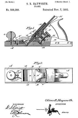
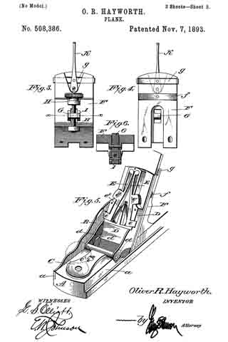
In the accompanying drawings, forming part of this specification, Figure 1 is a side view of the plane, partly in section. Fig. 2 is a plan view. Fig. 3 is a rear elevation of the part of the plane against which the bit rests. Fig. 4 is a front elevation of Fig. 3. Fig. 5 is a detail perspective view of the front portion of the plane with the cover of the pivoted holding cap removed; and Fig. 6 is a sectional view through the line x–x of Fig. 3.
A designates the base or bed-piece of the plane, which is preferably made of wood, the side edges thereof being cut away, as shown at a, to receive the metallic side pieces B which are secured to said base by the screws or bolts b. The base is slotted in the usual manner for the passage of the bit, and it is also recessed in its upper surface to receive the frames which adjust and hold the bit.
C designates a knob-plate, which is apertured near its forward end for the passage of the screw which secures the front knob c to the base. In rear of the aperture for the knob the plate is slotted for the passage of a set-screw or bolt c’, and to the rear end of the knob-plate is pivoted the holding cap D the rear face of which is adapted to bear upon the cap-plate of the bit. The lower end of the pivoted holding cap is out away to allow a free passage of the shavings, and the inner sides of the connecting arms d d are beveled, as shown at d’, so that the shavings will be guided toward the center of the plane. The pivoted holding cap is made in two parts, one part constituting the main frame and the other a covering plate, D’, which covering plate retains in place spring-actuated arms E E which have at their lower ends projecting catches which engage with notches or recesses in the side pieces B B of the plane so as to retain the pivoted holding cap in proper position. Above the catches e e the arms are provided with projections e’, which extend through the side pieces of the pivoted holding cap and provide means for retracting the catches, said catches being normally projected by means of a flat spring e2 which is positioned as shown in Fig. 5. The upper ends of the arms are rounded as shown to provide bearing surfaces or pivots.
It will be seen that by the construction hereinbefore described the knob-plate can be adjusted longitudinally upon the base of the plane to take up the wear of the parts and also to permit the use of bits and cap-plates of different thicknesses.
To the metallic side pieces and the base is rigidly secured the seat or frog provided for the bit, indicated by the letter F. This seat or frog is out away centrally for the passage of the adjusting lever G, said lever being pivoted between lugs which project from the rear side of the seat or frog, and above and below the lever project lugs H H in which is seated an adjusting screw having a head of ordinary construction. The central portion of the adjusting screw is threaded and engages with a threaded aperture in a block I pivoted within the rear end of the adjusting lever, said rear end being bifurcated to receive the block. By this construction I am enabled to provide rigid bearings for the adjusting screw and position the same so that it will be on a line with the front bearing surface of the frog F. The block I is slotted for the passage of the pivot-pin.
The frog is provided with a transverse recess in which is secured a flat spring f the free ends of which bear upon the rear surface of the bit, and above this spring the frog is provided with another transverse recess for the reception of a plate g having outturned ends which engage with the sides of the plane-bit, the rear side of the frog being recessed to receive a lever K which is pivotally attached to the plate g and to a stud or projection on the frog, the recess for the lever opening into the recess in which the plate slides.
The lower end of the lever K is bifurcated to embrace the stud or projection. The bit and cap-plate therefor are of substantially ordinary construction and are connected to each other by the screw L, and above the screw the cap-plate has a recessed lug, M, with which the forward end of the adjusting-lever G engages.
It will be observed that by simply turning the thumb-screw H the bit and its cap-plate may be adjusted vertically, and that the bit can be adjusted so that its cutting edge will be on a line with the under side of the plane by the use of the lever K.
When it is desired to remove the bit from the plane-stock it can be readily accomplished by simply pressing upon the projections e’ e’ of the arms E E, which will retract the catches and permit the holding cap to be swung upon its pivot.
I am aware that prior to my invention it has been proposed to provide a bench-plane with means for vertically and laterally adjusting the bit, and I do not therefore claim such construction broadly; but
What I do claim as new, and desire to secure by Letters Patent, is —
1. A bench plane comprising a wooden base having longitudinal side recesses, a transverse aperture of less width than the base through which the bit passes and recesses in front and rear of said transverse aperture, metallic side pieces secured to the base so as to lie partially in the longitudinal side recesses thereof, a knob-plate secured to the base so as to be located partially in the recess in front of the transverse aperture, a seat or frog attached to the base and metallic side pieces, the lower portion thereof lyin gin the recess in rear of the transverse aperture, and a holding cap pivoted to the rear end of the knob-plate, the parts being organized and combined substantially as shown, and for the purpose set forth.
2. In a plane, the combination, of a frog rigidly attached to the base and side pieces thereof, a cap-plate pivoted to the base of the frame and connected thereto so as to be adjustable longitudinally thereon, said cap-plate having catches which engage with recesses in the side pieces of the frame, for the purpose set forth.
3. In combination with a plane, the side pieces thereof having recesses on their inner sides, a holding cap which is pivotally secured to the base of the plane, said cap carrying spring-actuated catches which are adapted to engage with the recesses in the side pieces, for the purpose set forth.
4. In combination with a plane, a movable plate having pivoted thereto a cap-piece, said cap-piece having forwardly projecting portions the sides of which are cut away above the opening through which the bit passes, and catches for holding the cap-piece in engagement with the side pieces of the plane, substantially as shown.
5. In combination with a plane, an adjustable plate C, a holding cap having forwardly and downwardly extending portions pivotally attached to the adjustable plate, catches carried by the holding plate and adapted to engage with recesses in the sides of the plane, substantially as shown, and for the purpose set forth.
6. In a plane, the combination, of the pivoted holding cap the upper portion of which is recessed for the reception of arms having at their lower ends outwardly projecting catches and intermediate projections e’ e’ to provide for retracting the catches, together with a spring for projecting the arms, substantially as shown, and for the purpose set forth.
In testimony whereof I affix my signature in presence of two witnesses.
OLIVER R. HAYWORTH.
Witnesses:
A. L. GRAY,
C. R. BARROW.