No. 1,021,369 – Plane (Thomas A. Manley) (1912)
[paiddownloads id=”681″]1021369


UNITED STATES PATENT OFFICE.

_________________

THOMAS A. MANLEY, OF AUBURN, NEW YORK, ASSIGNOR TO OHIO TOOL COMPANY, OF AUBURN, NEW YORK, A CORPORATION OF NEW YORK.

PLANE.

_________________

1,021,369. Specification of Letters Patent. Patented Mar. 26, 1912.
Application filed January 18, 1912. Serial No. 671,879.

_________________

To all whom it may concern:

Be it known that I, THOMAS A. MANLEY, a citizen of the United States, residing at Auburn, in the county of Cayuga and State of New York, have invented certain new and useful Improvements in Planes, of which the following is a specification.

This invention relates to improvements in planes, and has for its object to provide novel, simple, convenient and effective means for adjusting the plane-frog longitudinally for facilitating the setting of the bit or plane iron in different positions in the throat of the plane body.

A further object is to provide novel and simple means for locking the frog after the same has been adjusted. And a particular object of the invention is to provide convenient and effective means for adjusting and locking the frog without disturbing the plane iron and related parts.

The various features and parts and the operation of the same, will be fully set forth in the detailed description which follows, illustrated in the accompanying drawing, and then particularly pointed out in the claims.

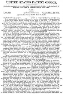
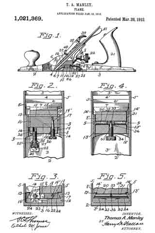
Figure 1 is a side elevation and part section of my complete plane. Fig. 2 is a horizontal section, taken on line 2–2 of Fig. 1. Fig. 3 is a vertical cross-section, taken on line 3–3 of Fig. 2. Fig. 4 is a horizontal section similar to Fig. 2; showing a modification of the locking and adjusting means. Fig. 5 is a vertical cross-section, taken on line 5–5 of Fig. 4.

Similar characters of reference designate like parts throughout the several views.

In the drawing, 2 represents the body of the plane, 3 the sole, 4 the throat or mouth, and 5 the cheeks or lateral guards which are formed integral with the body. The rear side or edge of the throat 4 is formed sharp and thin, and then the metal inclines upwardly and rearwardly at a slight angle for forming a smooth bearing surface 6 which extends across the upper side of the sole 3, to receive a correspondingly formed forwardly projecting portion 7 of the frog 8. The frog 3 consists of an irregularly shaped casting or part having a rearwardly and upwardly inclining top surface 9, for receiving and supporting the plane iron or bit 10, and having a substantially plain horizontal bottom 11, which bears and slides upon a comparatively long elevated step or portion 12, preferably an integral part of the body of the plane. The elevation or seat 12 is disposed a short distance rearwardly of the inclined bearing 6, and its top surface lies in a higher plane than the said bearing. The under side of the frog is correspondingly shaped, so that when the bottom 11 of the frog rests upon the elevation 12, the forward end 7 approaches close to the sloping surface 6. 13 represents like inwardly facing angular ribs or tongues formed horizontally on the cheek pieces 5, directly above the opposite side-edges of the elevated bearing 12, and 14 represents hollow corners or grooves formed in the opposite bottom corners of the frog, the said hollow corners preferably being formed right-angled, so as to clear the ribs 13 when the frog is moved to and fro over the body of the plane. The tongues or ribs 13 are triangular in cross-section, and preferably extend the length of the elevated bearing 12, and they are disposed parallel to said bearing, so that the frog, when operatively connected with the tongues, may be freely moved forward and backward in a true and level plane. The tongues 13 are of sufficient length and strength to effectually hold the frog from chattering while the plane is in operation.

To hold the frog 8 in place on the base 2, and yet allow said part to be freely moved to and fro for adjusting the cutting-blade or bit 10 relatively to the throat 4, the underside of the frog is provided with a broad transverse dove-tail groove or slot 15, in which is operatively fitted a pair of correspondingly shaped keys or locking members 16–17. The keys 16–17 are disposed end to end, in the slot or way 15, and their combined length is slightly less than the breadth of the bearing surface 12 beneath the tongues or guides 13, the outer ends of the keys 16–17 then project beyond each side of the bottom of the frog, as shown in Figs. 2 and 3. The outer ends of the keys 16–17 are beveled to correspond to the under-cut sides of the tongues 13 (see Fig. 3). The abutting ends of the keys 16–17 are provided with transverse concaves 18, the said concaves tapering toward the forward end of the frog.

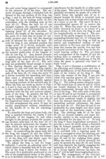
19 represents a set-screw having a tapering point 19′ extending beyond the threads, the said point being tapered to correspond to the concaves 18 of the keys. The set-screw 19 passes through a threaded hole 20 formed in the rear portion of the frog (see Figs. 1 and 2), the hole 20 being arranged to bring the set or locking screw 19 into coincidence with the abutting ends of the keys 16–17. When the keys 16–17 are brought together, the opposite concaves 18 form a tapering hole corresponding to the tapering point 19′ of the set-screw. In practice, the length of the tapering end of the screw 19 is such that its point 19′ normally projects part way into the tapering hole 18 between the ends of the keys. To lock the frog in any adjusted position the wedge screw 19 is driven inwardly until its tapering end 19′ spreads and forces the keys 16–17 in opposite directions against the beveled under-sides of the tongues or ribs 13 (see Fig. 3). Any desired pressure or tension may be produced by means of the wedging of the screw 19 between the abutting ends of the keys 16–17. The said keys are preferably broad enough to insure a firm bearing beneath and against the tongues 13, and will hold the frog rigidly in place. By the provision of the beveled ends of the keys 16–17, when the screw 19 is driven inwardly for spreading said keys, they exert a downward pressure which forces and holds the frog rigidly against the bearing surfaces of the elevated seat 12. When the keys are made as shown in Figs. 1, 2 and 3, they are not liable to wear seats in the under-side of the ribs 13, which will interfere with the line and accurate adjustment of the frog. In practice the key 16 is made longer than the key 17, so as to bring the abutting ends (18) to one side of the longitudinal center of the body 2. Under this arrangement the screw 19 may be readily manipulated without interference by the handle 21 or the bit adjusting-screw 22.

To assemble the frog and plane body, the frog is inserted between the cheeks 5 just forwardly of the tongues 13, and when brought to the proper position the projecting beveled outer-ends of the keys 16–17 may be entered underneath the tongues 13, after which the frog may be moved rearwardly until brought to the desired position. In constructing the plane body and the frog, the tongues 13 and the hollow-corners 14 are arranged so that the bottom 11 of the frog will rest firmly upon the upper surface of the elevated seat 12.

To adjust the frog to and fro longitudinally, I provide an adjusting screw 25 which enters a threaded hole 26 in the rear side of the frog 8 above the bottom 11. The screw 25 is preferably positioned at one side of the longitudinal center of the plane, so as to facilitate adjusting the frog without interference by the handle 21 or other parts of the plane. The screw 25 is held from longitudinal movement by means of a yoke 27 which forms the upright arm of an L-shaped bracket 28 which is mounted upon the upper side or face of the sole 3, by means of a screw or pin 29. The screw 25 has a circumferential groove 25′ to receive the yoke 27. When the screw 25 is turned in either direction by hand or by means of a screw-driver, it will move the frog to and fro longitudinally on the base 2. The provision of the guide tongues 13 and the corresponding beveled keys 16–17 will prevent vertical movement of the frog, as well as, lateral and longitudinal rocking of said part relative to the base, and this arrangement also insures the smooth, free and true horizontal movement of the frog on the elevated bearing surface 12. The provision and arrangement of the tongues 13 and the locking keys or members 16–17 will also effectually obviate the chattering of the bit when the plane is operated over hard or burly wood.

Figs. 4 and 5 illustrate a modification of the adjusting and locking parts, and also a slight modification of the form and arrangement of the bottom of the frog 8′. The lower side corners of the frog 8′ are provided with annular grooves 14′, which conform to the shape of the tongues 13′ (see Fig. 5). The locking means comprise apair of like round keys or pins 30 and 31 which are loosely disposed in a hole 32 which passes transversely through the lower portion of the frog. The outer ends of the pins or keys 30 and 31 are beveled to correspond to the under-out sides of the guide ribs 13′, and their combined length is slightly less than the distance between the ribs 13′, for permitting endwise adjustment, the same as the keys 16–17. The keys 30 and 31 are preferably the same length, and their inner ends meet at the transverse center o-f the frog. The abutting ends 33 of the keys 30–31 are formed concave, and taper forwardly, similar to the construction shown and described for the keys 16–17. To lock the frog 8′ from longitudinal movement, I provide a screw 34 which enters a threaded hole 35 formed centrally in the rear-part of the frog 8′. The inner end of the screw 34 is provided with a tapering point 36, which is arranged to enter the tapering concaves arranged in the abutting ends of the keys 30 and 31 for wedging them apart. When the screw 34 is driven inwardly the point 36 spreads the keys 30–31 and forces said keys laterally for tightly engaging the underside of the ribs 13′. When the screw 34 is driven tightly between the keys, the frog 8′ will be held from longitudinal movement. The arrangement of the dove-tail tongues 13′ and the similar grooves 14′ is such that, the frog cannot be moved vertically until it is withdrawn free from the ribs. To adjust the frog 8′ to different positions longitudinally, the screw 34 is first loosened up, and then the frog may be shifted to and fro, and set in the desired position, by hand.

The plane iron or bit 10 is provided with the usual guard plate 37, and is held in place by a cap 38, which is fitted with the usual clamping part 39.

40 represents a screw carried by the frog for engaging the cap 38. The adjusting screw 22 is employed for shifting the plane iron longitudinally on the frog, and a lever 41 is employed for adjusting the plane iron laterally.

The locking means comprising the keys and the wedge screws are extremely simple, yet affording powerful means for locking the frog to the frame. When these parts are properly made and assembled, but a slight movement of the screws 19 and 34 in either direction will effect the rigid locking or the unlocking and freeing of the frog. The broad keys 16–17 cooperating with the side ribs 13 tend to steady the frog during its forward and backward movements. The disposition of the screws 19 and 25 at or near the sides of the plane render the locking and adjusting parts conveniently accessible, and in view of the location and arrangement of these parts the locking and adjusting of the frog may be accomplished without disturbing the plane-iron or any other part.

Having thus described my invention what I claim as new and desire to secure by Letters Patent, is —

1. In a plane, the combination with a sole having a throat and an elevated seat arranged rearwardly of said throat, of a frog having a plane bottom adapted to rest and slide upon said seat, said frog having longitudinal grooves formed in its opposite bottom corners, a pair of angular tongues carried by the body of the plane, said tongues received by said grooves, and adjustable means carried by said frog adapted to engage said tongues for guiding and locking said frog.

2. In a plane, the combination with a sole having a throat and an elevated seat arranged rearwardly of said throat, of a frog having a plane bottom adapted to rest and slide upon said seat, said frog having longitudinal grooves formed in its opposite bottom corners, a pair of angular tongues carried by the body of the plane, said tongues received by said grooves, adjustable means carried by said frog adapted to engage said tongues for guiding said frog, and a screw cooperating with said means for locking said frog rigidly to the elevated seat.

3. In a plane, the combination with a sole having a throat and an elevated seat arranged rearwardly of said throat, of a frog having a plane bottom adapted to rest an slide upon said seat, said frog having longitudinal grooves formed in its opposite bottom corners, a pair of angular tongues carried by the body of the plane, said tongues received by said grooves, adjustable means carried by said frog adapted to engage said tongues for guiding and locking said frog, and a swivel-screw for adjusting said frog to different positions on said sole.

4. In a plane, the combination with a sole having spaced cheek pieces and having an elevated seat between said cheek pieces, of horizontal guide-ribs formed on the inner sides of said cheek pieces above and parallel to the said seat, a frog having a plane bottom slidable upon said seat, the opposite lower corners of said frog cut away to clear said ribs, a pair of keys disposed end to end in a transverse slot formed in the bottom of said frog, said keys having their outer ends beveled to pass under and to engage said ribs, and a tapering screw for spreading said keys apart for locking the frog to said ribs.

5. In a plane, the combination of a sole having a transverse throat and an inclined bearing adjacent the throat, and having an elevated seat adjacent the inclined bearing, triangular ribs formed above and parallel to the said elevated seat, a frog having a plane bottom surface adapted to engage and slide upon said elevated seat between said ribs, said frog having portions out-away for clearing said ribs, and a pair of transversely movable keys carried by said frog adapted to engage said ribs for guiding and also for locking said frog.

6. In a plane, the combination of a frame comprising a sole and spaced cheek pieces, a raised seat formed on the sole between the cheek pieces, an inwardly facing tongue carried by each cheek piece disposed horizontally above said raised seat, said tongues having their facing sides under-cut, a frog slidable on the said raised seat between the said tongues, but free from said tongues, transversely movable keys carried by the frog having beveled outer ends adapted to slide beneath the under-out sides of said tongues for guiding said frog when moved to and fro on said seat, and a wedge-screw carried by said frog adapted to force and hold said keys against said tongues for locking said frog from movement in any direction.

7. In a plane, the combination with a body having an integral elevated seat lying between like cheeks projecting upwardly on its opposite sides, and ribs formed on the inner sides of said cheeks and overhanging said elevated seat, said ribs disposed parallel to the said elevated seat and also to the sole of the body, of a frog having a plane bottom surface adapted to engage and slide upon the said elevated seat, said frog having its opposite bottom corners. cut-away to receive said ribs, and means carried by said frog adapted to engage said ribs for holding said frog from vertical movement.

8. In a plane, the combination of a frame comprising a sole and spaced cheek pieces, a raised seat formed on the sole between the cheek pieces, an inwardly facing; tongue carried by each cheek piece disposed horizontally above said raised seat, said tongues having their facing sides under-cut, a frog slidable on the said raised seat between the said tongues, but free from said tongues, transversely movable keys carried by the frog adapted to slide beneath the under-cut sides of said tongues for guiding said frog when moved to and fro on said seat, a wedge-screw carried by said frog adapted to force and hold said keys against said tongues for locking said frog from movement in any direction, and a swivel-screw for adjusting said frog to different positions in the said frame.

9. In a plane, the combination with a body having an integral elevated seat, said body having like cheeks projecting upwardly on its opposite sides, and ribs formed on the inner sides of said cheeks and overhanging said elevated seat, said ribs disposed parallel to the said elevated seat and also to the sole of the body, of a frog having a plane bottom surface adapted to engage and slide upon the said elevated seat, said frog having its opposite bottom corners cut-away to receive said ribs, means carried by said frog adapted to engage said ribs for guiding said frog during its longitudinal movements, and means for adjusting said frog to different positions on said elevated seat.

10. In a plane, the combination of a body having vertically disposed lateral guards, ribs carried by the inner faces of said guards, said ribs arranged parallel to the sole of said body, an elevated step disposed beneath and parallel to said ribs, a frog having a substantially flat bottom adapted to rest and slide upon said elevated step, the opposite sides of said frog cut-away to clear said ribs, transversely disposed keys carried by said frog, the outer ends of said keys projecting beyond said frog adapted to engage the under-cut edges of said keys for holding said frog firmly upon said step, said keys and said ribs cooperating for guiding said frog when moved to and fro on said body, and a wedge-screw carried by said frog adapted for spreading said keys for rigidly locking said frog to the said ribs.

11. In a plane, the combination of a sole having a transverse throat and an inclined bearing adjacent the throat, and having an elevated seat adjacent the inclined bearing, triangular ribs disposed above and parallel to the said seat, a frog having a plane bottom surface adapted to engage and slide upon said seat between said ribs, a pair of keys carried by said frog adapted to engage said ribs for guiding and also for locking said frog, and a screw for adjusting said frog to different positions relative to said throat.

In testimony whereof I affix my signature in presence of two witnesses.

THOMAS A. MANLEY.

Witnesses:
G. W. BAYNON,
N. L. CASEY.

_________________

Copies of this patent may be obtained for five cents each, by addressing the “Commissioner of Patents, Washington, D. C.”
_________________

No. 864,101 – Plane (Edward S. Marks) (1907)

[paiddownloads id=”644″]864101


UNITED STATES PATENT OFFICE.

_________________
EDWARD S. MARKS, OF AUBURN, NEW YORK, ASSIGNOR TO OHIO TOOL COMPANY, OF AUBURN, NEW YORK, A CORPORATION OF NEW YORK.

PLANE.

_________________
864,101. Specification of Letters Patent. Patented Aug. 20, 1907.
Application filed March 7, 1907. Serial No. 361,030.

_________________

To all whom it may concern:

Be it known that I, EDWARD S. MARKS, a citizen of the United States, residing at Auburn, in the county of Cayuga and State of New York, have invented or discovered certain new and useful Improvements in Planes, of which the following is a specification, reference being had therein to the accompanying drawings.

This invention relates generally to bench planes and more particularly to the manner of seating the “frog”, or support for the bit or cutting iron, upon the sole or bottom of the plane. In planes of this character the frog is ordinarily made in a piece separate from the body or stock of the plane and bolted or otherwise secured thereto, and is adjustable longitudinally of the plane body in order to permit the effective size of the throat or opening in the sole of the plane to be varied. When, however, a frog of this character is adjusted to a position in which its forward or bit-supporting face lies in a plane in advance of the rear edge of the throat or opening in the sole, the lower end of the bit is left unsupported for a distance above its cutting edge equal to the thickness of the sole. In order to remedy this defect and to provide a support for the bit as near the cutting edge thereof as possible it has been proposed to provide a thinned down portion of the sole at the rear of the mouth or throat by cutting away the sole at its upper side at this point, and to provide the frog with a depending lip at its forward side which is received in the recess formed by cutting away the sole as above described, and which is adapted to support the bit at a point close to its cutting edge. It is necessary, however, in order to prevent rattling of the parts and to provide a firm support for the bit against the thrust of the plane, that the frog have a firm bearing upon the sole of the plane at a plurality of points and that it be firmly and tightly bolted or otherwise secured thereto. In the construction last referred to one of the supports of the frog upon the sole is provided by causing the depending lip on the frog to bear upon the thinned down portion of the sole at the rear of the throat. This is undesirable, since when the bolts which secure the frog to the sole are screwed down tightly the bearing of the lip of the frog upon the thinned down and therefore weakened portion of the sole tends to spring said thinned down portion out of the plane of the lower surface of the sole, thereby seriously impairing the efficiency of the plane.

One object, therefore, of my invention is to provide means for supporting a frog of the character above referred to in such a manner that the bit is supported at a point close to the cutting edge thereof while no tendency to warp any portion of the sole out of its proper plane is produced.

A further object of my invention is to dispense with the heavy raised frog seats which have been heretofore used in planes of this character, thereby simplifying the manufacture of these planes and reducing their weight.

A still further object of my invention is to improve certain details of construction in planes of this character, as will hereinafter appear.

To these ends my invention consists in certain constructions and combinations of parts hereinafter described and particularly pointed out in the claims.

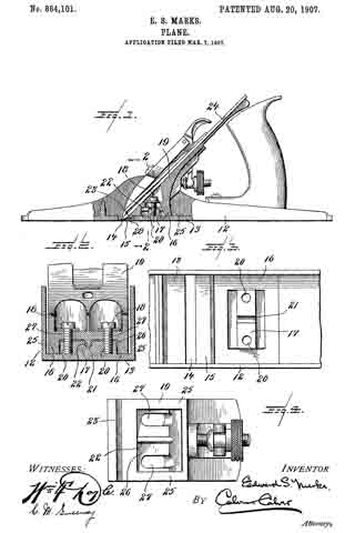
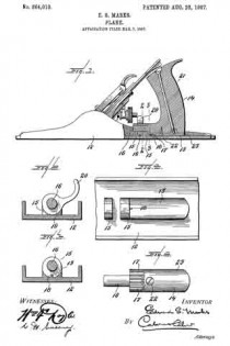
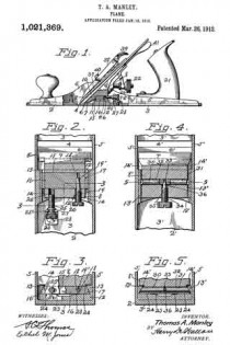
Referring to the drawings accompanying and forming part of this specification, Figure 1 is a side elevation, partly in section, of a plane made in accordance with my invention. Fig. 2 is a cross section of the plane stock and frog, taken substantially on the line 2–2, Fig. 1. Fig. 3 is a plan of a portion of the sole with the frog removed, showing the frog seat. Fig. 4 is a bottom plan view of the seating portion of the frog.

Like characters indicate like parts throughout the several views of the drawings.

12 indicates the stock or body of the plane, having a sole 13 provided with the usual throat or mouth 14, at the rear of which the sole is cut away at its upper side to provide a thinned down portion 15. Directly in the rear of said thinned down portion 15 is formed, preferably upon the sole of the plane itself, a single, continuous frog seat 16.

The frog seat 16 is adapted, alone, to support the frog, and to this end it is made of sufficient area to provide the necessary extended bearing surface to seat the frog firmly and to prevent any rocking movement thereof. The seat 16, as shown, lies wholly in a single plane substantially coincident with the upper surface of the sole, and, in the embodiment of my invention herein illustrated, is constructed in the form of a hollow rectangle, although it is obvious that many changes in the specific form of this seat might be made without departing from the spirit of my invention.

Located within and surrounded by the seat 16, and extending transversely of the sole of the plane, is a boss or rib 17. This rib is provided in order to furnish sufficient thickness of material to insure a secure engagement of the bolts 18, 18, which serve to clamp the frog 19 to its seat. To this end the boss or rib 17 is provided with threaded openings 20, for the reception of the attaching bolts 18. Preferably and as herein shown the rib 17 is provided with a transverse groove or notch 21 for the reception of a guiding or centering rib 22, on the frog 19. It will thus be seen that the boss or rib 17, provides means for engaging the attaching bolts 18, 18, and also means for guiding or preventing undue lateral movement of the frog 19, but in no other sense does the boss 17 support the frog, there being a slight clearance provided between the upper surface of the boss 17 and the opposite lower surface of the frog 19, and between the bottom of the groove 21 and the crest of the rib 22.

The frog 19 is provided with a depending lip 23, for supporting the bit 24 close to its cutting edge, and with a continuous seating portion 25, codperating with the seat 16. Surrounded by said seating portion 25 is a recess 26, for the reception of the boss 17 in the bottom of which recess is located the rib 22, and the slots 27, 27, for the passage of the attaching bolts 18, 18.

It will be noticed that a slight clearance, indicated by the numeral 28 in Fig. 1, is provided between the lower edge of the lip 23, and the thinned down portion 15 of the sole. These two parts are never allowed to come into engagement with one another, and all tendency to distort or warp this necessarily weak part of the sole is entirely prevented. The continuous frog seat 16 is oi sufficient extent to provide an absolutely firm bearing for the frog without any necessity for the frog to find an additional bearing on the thinned down portion 15 of the sole. Moreover my construction provides a wide seating area for the frog combined with a compactness of parts which is very desirable.

It will be further noticed that the frog is seated directly upon the sole, thus doing away with the heavy raised portions which have heretofore been considered necessary in order to provide the necessary bearings for the attaching screws of the frog, but which are difficult to cast satisfactorily, and which support the frog in an objectionably high position, or which have been omitted at the expense of the strength and durability of the plane. In my construction, however, the relatively small lug 17, which is not difficult to cast, provides sufficient thickness of metal to hold the attaching screws firmly, while the frog has a broad, flat, and desirably low support.

While I have shown and described one form in which my invention may be embodied, I wish it to be distinctly understood that I do not limit myself to the precise construction shown, it being obvious that many changes may be made therein without departing from the spirit of my invention.

Having thus described my invention I claim and desire to secure by Letters Patents —

1. In a plane, the combination with a sole having a frog seating surface lying in a single plane and a raised boss or rib provided with frog attaching means, of a frog having a plane seating surface adapted to cooperate with the seating surface on said sole, and cooperating means on said boss or rib and said frog for preventing relative lateral movement of said frog and sole.

2. In a plane, the combination with a sole having a single plane frog seating surface and a raised boss or rib provided with a groove, of a frog having a recess to receive said boss and a rib adapted to cooperate with said groove.

3. In a plane, the combination with a sole provided with a frog seating surface lying in a plane substantially coincident with the remainder of the upper surface of said sole and with a boss or rib rising above the plane of said frog seating surface, of a frog provided with a single seating surface adapted to coijperate with the seating surface on said sole and with a recess to receive said boss or rib, means cooporating with said boss or rib for attaching said frog to said frog seat, and coperating means on said boss or rib and said frog for preventing relative lateral movement of said frog and sole.

4. In a plane, the combination with a sole provided with a frog seating surface lying in a plane substantially coincident with the remainder of the upper surface of said sole and with a boss or rib rising above the plane of said frog seating surface, said boss or rib having a threaded aperture, of a frog provided with a single seating surface adapted to cooperate with the seating surface on said sole and with a recess to receive said boss or rib, a bolt cooperating with the aperture in said boss or rib for attaching said frog to said frog seat, and coiiperating means on said boss or rib and said frog for preventing relative lateral movement of said frog and sole.

5. In a plane, the combination with a frog having a depending lip, of a sole provided with a throat or mouth, a thinned down portion in the rear of said throat or mouth, a frog-seating surface lying in a plane substantially coincident with the remainder of the upper surface of said sole, and a boss or rib rising above the plane of said frog seating surface, means cooperating with said boss or rib for securely clamping said frog to said seat, said depending lip being out of contact with said thinned down portion, and coiiperating means on said boss or rib and said frog for preventing relative lateral movement of said frog and sole.

6. In a plane, the combination with a frog, of a sole having a throat or mouth. a frog seating surface in the rear of said mouth, and lying in a plane substantially coincident witli the remainder of the upper surface of said sole, and a boss or rib rising above the plane of said frog seating surface and provided with a frog-attaching means, and cooperating means on said boss or rib and said frog for preventing relative lateral movement of said frog and sole.

7. In a plane, the combination with a frog, of a sole having a plane frog seating surface and a raised boss or rib, and cooperating means on said boss or rib and said frog for preventing relative lateral movement of said frog and sole.

In testimony whereof I affix my signature, in presence of two witnesses.

EDWARD S. MARKS.

Witnesses:
JOHN W. BRAINARD,
RALPH R. KEELER.

No. 864,010 – Plane (Edward S. Marks) (1907)

[paiddownloads id=”643″]864010


UNITED STATES PATENT OFFICE.

_________________

EDWARD S. MARKS, OF AUBURN, NEW YORK, ASSIGNOR TO OHIO TOOL COMPANY, OF AUBURN, NEW YORK, A CORPORATION OF NEW YORK.

PLANE.

_________________

864,010. Specification of Letters Patent. Patented Aug. 20, 1907.
Application filed March 7, 1907. Serial No. 361,029.

_________________

To all whom it may concern:

Be it known that I, EDWARD S. MARKS, a citizen ofthe United States, residing at Auburn, in the county of Cayuga and State of New York, have invented or discovered certain new and useful Improvements in Planes, of which the following is a specification, reference being had therein to the accompanying drawings.

My invention relates to adjustable handles for planes.

The object of my invention is to provide a handle of the character specified which shall be simple in character, which may be easily and quickly adjusted to any desired position, and which will be securely and rigidly held in its adjusted position.

To these ends my invention, in its preferred form, comprises a handle rockingly mounted on a concave seat with which the base of the plane is provided, cooperating devices on the handle and base, which, when in engagement with one another, are adapted to hold the handle against tilting movement, and means for securely locking the handle in a position with said interlocking devices in engagement with one another.

While, as above stated, I prefer to form the handle and its seat on the base of the plane with interlocking devices I consider it to be within the scope of my invention to omit these devices and to hold the handle in its adjusted position by means of the aforesaid locking means alone, or to form these cooperating interlocking devices upon the handle and some part of the body of the plane other than the base thereof.

One construction in which my invention may be embodied is illustrated in the accompanying drawings, in which:–

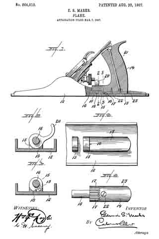
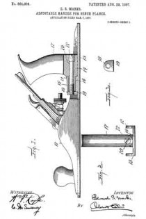
Figure 1 represents a longitudinal section through the handle portion of a plane constructed in accordance with my invention. Figs. 2 and 3 are cross-sectional views taken on the lines 2–2 and 3–3, respectively, Fig. 1. Fig. 4 is a plan view of the base of the plane shown in Fig. 1, with the handle member and clamping device removed. Fig. 5 is a bottom plan view of the handle member shown in Fig. 1.

Like characters indicate like parts throughout the several views of the drawings.

The base 12 of the plane is provided with a concave seat 13, firmly supporting the handle member 14 rockingly seated thereon, and with means for further pivotally supporting said handle member, said means as herein shown comprising a pair of upstanding, perforated lugs 15, 15, formed integral with the base 12. The handle member 14 is provided with a fixed, rigid, forwardly projecting pintle 16, adapted to enter the perforations in the lugs 15, 15, and is preferably formed with a convex under surface to cooperate with the concave seat 13.

As heretofore stated, I prefer to form the handle member and base with cooperating interlocking devices adapted to prevent rocking movement of the handle member when said devices are in engagement with one another, and to this end, in the construction shown, the handle member 14 is provided on its under surface with a plurality of’ grooves or recesses, 17, 17, while the base of the plane, at the junction of the seat 13 with the base of the rearmost lug 15, is provided with a lug 18, adapted to enter any one of the grooves 17, 17, according to the angular position of the handle member 14.

Means are provided for clamping the handle member 14, and for holding the same securely against any movement longitudinally of the plane. This means, in the construction shown, comprises an eccentric locking device 19, rotatably mounted on the pintle 16, between the lugs 15, 15. The locking device 19 is provided with a finger piece 20 by means of which it may be operated, and is adapted, when in its operative position, as shown in Fig. 2, by means of a wedging action between the base 12 and the pintle 16, to force the pintle 16 tightly against the upper sides of the perforations in the lugs, 15, 15, thereby securely holding the handle member against either longitudinal or rotary movement.

As herein shown the handle member 14 comprises a wooden handle 21, to which is permanently attached, as by a suitable screw 22, a metal shoe 23, the pintle 16, and grooves 17, 17 being formed upon said shoe 23. lt will be obvious, however, that the handle member 14, might be made in a single piece from suitable material.

In order to adjust the handle to any desired position, the finger piece 20 is raised from the position shown in Fig. 2, thereby releasing the locking device 19. The handle member 14 is then moved bodily backward until the lug 18 is clear of the groove 17, 17, after which the handle is turned into the desired position with one of the grooves 17, 17, opposite the lug 18. The handle is then moved forward into its original longitudinal position, thereby causing the lug 18 to enter the desired groove 17, and the locking device 19 again moved to locking position.

While I, in order that my invention may be more easily understood, have described the same as embodied in the particular construction shown, I wish it to be distinctly understood that I do not limit myself to this construction, it being obvious that many changes might be made therein without departing from the spirit and scope of my invention.

The concave seat 13 herein shown provides a much firmer support for the handle member than is provided in any construction of which I am aware.

Having thus described my invention I claim and desire to secure by Letters Patent:

1. In a plane, the combination with a concave handle seat, of a handle rockingly mounted thereon for angular movement transverse to the plane, and devices for retaining said handle in adjusted position.

2. In a plane, the combination with a base provided with a concave handle seat, of a handle rockingly mounted on said seat and pivotally connected to said base, and devices for retaining said handle in adjusted position.

3. In a plane, the combination with a handle mounted for angular adjustment and for longitudinal movement, of means for engaging said handle to hold the same against angular movement when in one longitudinal position, and means for locking said handle against longitudinal movement.

4. In a plane, the combination with a base provided with a curved handle seat, a locking lug, and one or more perforated lugs, of a handle member with a curved base to cooperate with said curved seat, a plurality of grooves adapted to cooperate with said locking lug, and with a forwardly projecting pintle entering said perforated lugs, and a clamping device engaging said pintle.

5. In a plane, the combination with a concave handle seat provided with a projecting lug, of a handle provided with a plurality of grooves adapted to receive said lug, and means for holding said handle with said lug in engagement with one of said grooves.

6. In a plane, a rockingly mounted handle, interlocking means on said handle and a fixed part oi the plane for holding said handle against rocking movement, said handle being bodily movable to release said interlocking means.

7. In a plane, the combination with a base provided with a concave handle seat, a locking lug, and one or more perforated lugs, of a handle member provided with a convex base, a plurality of grooves adapted to cooperate with said locking lug, and with a forwardly projecting pintle entering said perforated lugs, and a clamping device engaging said pintle.

8. In a plane, the combination with a plurality of bearing members, of a handle member having a projecting portion adapted to turn in said bearing members, and clamping means engaging said projecting portion beyond one of said bearing members.

In testimony whereof I affix my signature, in presence of two witnesses.

EDWARD S. MARKS.

Witnesses:
JOHN W. BRAINARD,
RALPH R. KEELER.

No. 864,009 – Adjustable Handle For Bench-Planes (Edward S. Marks) (1907)

[paiddownloads id=”642″]864009


UNITED STATES PATENT OFFICE.

_________________

EDWARD S. MARKS, OF AUBURN, NEW YORK, ASSIGNOR TO OHIO TOOL COMPANY, OF AUBURN, NEW YORK, A CORPORATION OF NEW YORK.

ADJUSTABLE HANDLE FOR BENCH-PLANES.

_________________

864,009. Specification of Letters Patent. Patented Aug. 20, 1907.
Application filed March 7, 1907. Serial No. 361,028.

_________________

To all whom it may concern:

Be it known that I, EDWARD S. MARKS, a citizen of the United States, residing at Auburn, in the county of Cayuga and State of New York, have invented or discovered certain new and useful Improvements in Adjustable Handles for Planes, of which the following is a specification, reference being had therein to the accompanying drawings.

My invention relates to improvements in adjustable handles for planes.

The object of my invention is to provide a reliable handle of the character specified which shall be simple in construction and which may be easily and quickly adjusted to any desired position.

To this end my invention comprises a preferably concave handle seat, a handle pivotally mounted on the body or stock of the plane and supported by said seat, and a device herein shown as a collar applied to the forwardly extending end of the handle and having a shoulder to bear against the sole of the plane, for locking the handle against tilting movement.

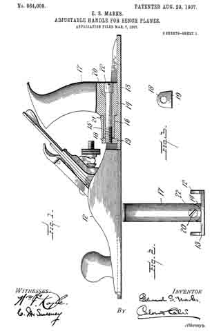
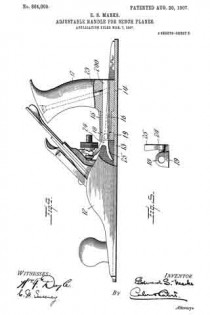
In the drawings accompanying and forming part of this specification, and illustrating a construction in which my invention may be embodied: Figure 1 is a vertical, longitudinal section of the handle portion of a plane constructed in accordance with my invention: Fig. 2 is a rear view of the same; Fig. 3 is an elevation of a collar hereinafter referred to; Fig. 4 is a view, similar to Fig. 1, of a modification. Fig. 5 is a view, similar to Fig. 3, of the collar used in the modification illustrated in Fig. 4.

Like reference characters indicate like parts throughout the several views of the drawings.

12 indicates the body or stock of the plane provided with the usual sole portion, 13. Upon the sole 13 is formed a concave handle seat 14, and an upstanding boss or lug 15 longitudinally bored to provide a bearing for a rounded, forwardly projecting portion 16 of the handle 17. The handle 17 is adapted to turn in its bearing in the boss 15, and to rock upon the seat 14 for the purposes of adjustment. Means are provided for locking the handle 17 in any desired position of adjustment, said means, as herein shown, comprising a collar 13, shown in detail in Figs. 3 and 5, having a shoulder or flattened portion 19 adapted to hear on the sole of the plane.

In the construction shown in Figs. 1 to 3, the collar 18 is formed as a nut adapted to engage the threaded end of a rod 20 passing through the handle 17, and the extension 16 thereof, and being provided at its rear end with a head 22, having means whereby said rod may be turned by means of a screw driver or other tool. The handle 17 is preferably provided with a shoulder 21, and when the rod 20 is turned to tighten the collar 18, the boss 15 will be clamped between the shoulder 21 and the collar 18, and the handle securely held against angular displacement, while the shoulder 19 on the collar 13 prevents rotation of the latter.

In the modification illustrated in Figs. at and 5 the collar 18 is provided with a smooth interior bore for the reception of an unthreaded rod 200, similar to the rod 20, but held against rotation in the handle 17 by a bolt 23. In this construction the collar 18 is tapped to receive a set screw 24, preferably provided with a finger piece 25. It will be obvious that when the set screw 24 is tightened upon the rod 200 the handle 17 will be securely held against turning or rocking movement, the shoulder 19, as heretofore stating, holding the collar 18 against rotation.

I do not limit myself to the precise constructions shown, it being obvious that many changes may be made in the details thereof without departing from the spirit or scope of my invention.

I claim:–

1. In a plane, the combination with a bearing, of a handle member having a projecting portion adapted to turn in said bearing, and clamping means engaging said projecting portion beyond said bearing.

2. In a plane, the combination with a bearing, of a handle member having a projecting portion rotatably mounted in said bearing, a collar detachably secured to said projecting portion beyond said bearing, and means for holding said collar against rotation.

3. In a plane, the combination with a sole and a bearing carried by said sole, of a handle member having a projecting portion rotatably mounted in said bearing, and a collar detachably secured to said projecting portion beyond said bearing, said collar having a shoulder engaging said sole.

4. In a plane, the combination with a sole provided with a bearing and a concave seat, of a handle member tiltingly mounted on said seat and having a projecting portion rotatably mounted in said bearing, and a collar detachably secured to said projecting portion beyond said bearing.

5. In a plane, the combination with a sole provided with a longitudinally bored boss, of a handle member seated upon said sole and having a projecting portion rotatably mounted in the bore of said boss, a rod extending longitudinally through said projecting portion, and a collar detachably secured to said rod beyond said boss.

6. In a plane, the combination with a bearing, of a handle member having a projecting portion rotatably mounted in said bearing, a collar mounted on said projecting portion beyond said bearing, and means for clamping said collar to said projecting portion.

7. In a plane, the combination with a bearing, of a handle member having a projecting portion rotatably mounted in said bearing, a rod extending longitudinally through said projecting portion, a collar mounted on said rod beyond said bearing, and a set screw in said collar engaging said rod.

8. In a plane, the combination with a bearing, of a handie member having a projecting portion rotatably mounted in said bearing, a rod extending longitudinally through said projecting portion, means for preventing rotation of said rod and said handle, a collar mounted on said rod beyond said bearing, and a set screw in said collar engaging said rod.

9. In a plane, the combination with a bearing, of a handle member, having a projecting portion rotatably mounted in said bearing, a rod extending longitudinally through said projecting portion, a collar mounted on said rod beyond said bearing, means for holding said collar against rotation, and a set screw in said collar engaging said rod.

In testimony whereof I aflix my signature, in presence of two witnesses.

EDWARD S. MARKS.

Witnesses:
JOHN W. BRAINARD,
RALPH R. KEELER.

No. 461,166 – Bench-Plane (Michael J. Dunn And William H. Montgomery) (1891)

[paiddownloads id=”479″]461166


UNITED STATES PATENT OFFICE.

_________________

MICHAEL J. DUNN AND WILLIAM H. MONTGOMERY, OF COLUMBUS,
OHIO, ASSIGNORS TO THE OHIO TOOL COMPANY, OF SAME PLACE.

BENCH-PLANE.

_________________

SPECIFICATION forming part of Letters Patent No. 461,166, dated October 13, 1891.
Application filed April 15, 1891. Serial No. 389,038. (No model.)

_________________

To all whom it may concern:

Be it known that we, MICHAEL J. DUNN and WILLIAM H. MONTGOMERY, citizens of the United States, residing at Columbus, in the county of Franklin and State of Ohio, have invented certain new and useful Improvements in Bench-Planes; and we do hereby declare the following to be a full, clear, and exact description of the invention, such as will enable others skilled in the art to which it appertains to make and use the same.

Our invention relates to mechanical appliances for effecting the up-and-down or longitudinal and the lateral or sidewise adjustments of a bench-plane bit; and it consists, first, in a longitudinally-adjusting mechanism comprising a pivoted lever-link and a screw-threaded link, the former being pivoted to the base or frog-plate of the plane and connected with the cap-iron of the bit, and the latter also connected to a bracket of said frog-plate and provided with a thumb-nut, as will be hereinafter described, whereby the adjustment back and forward on an inclined plane in a longitudinal direction can be perfectly and readily effected, and, while this is the case, the parts for making such adjustment are readily accessible.

It consists, second, in a novel combination of the bit, cap-plate, slotted frog-plate, and a lever having its lower end pivoted in the slotted upper end of the frog-plate and pivotally connected at its lower end to the upper end of the bit. By this construction the lateral adjustment of the bit for the purpose of bringing its cutting-edge parallel with the face of the plane, and thereby securing an even cut, is cfected, and as the lever is pivoted at nearly the extreme upper ends of the bit and frog-plate we are enabled to use fully two inches of the cutting-bit before substituting a new one therefor, and, while this is so, the lever is in convenient location for being manipulated by the user of the plane.

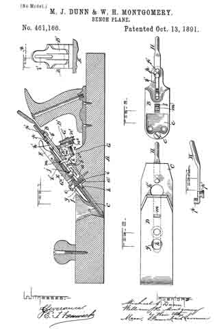
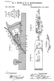
In the drawings, Figure 1 is a vertical longitudinal section of a bench-plane with our invention illustrated thereon. Fig. 1x is a detail back view of the frog-plate. Fig. 2 is a top view of the bit and its cap-plate, and the lever for effecting the lateral adjustment. Fig. 3 is a top view of the frog-plate, the connecting-screw, and the lever for effecting the lateral adjustment. Fig. 4 is a side view of the laterally-adjusting lever and its fulcrum-pivot.

A in the drawings represents the plane-stock, which is preferably of the construction shown, but may be of any other suitable construction adapted for having our invention applied to it.

B is an inclined base or frog-plate secured by screws in a shouldered mortise a, of the stock A and sustained by a projecting thickened portion b2, which bears upon the top of said stock, while the front end of the frog-plate abuts against the shoulder a’ at the front of the mortise of the plane-stock, as shown. This frog-plate is provided with a cavity c, a short longitudinal rectangular slot b, and a long longitudinal slot b’, as shown in the drawings.

C is the plane-iron; D, the cap-plate thereof, and E a clamping-plate for holding the cap-plate D and bit C in position. The three plates C, D, and E are connected together by a screw e, which passes through a key-hole-shaped passage f in the clamping-plate E, a round hole g in the plate D, and a long slot h in the bit C and enters a screw-threaded socket i at the lower end of the frog-plate B. The cap-plate D and the bit C are connected to each other directly by means of a headed nicked screw j, the shank of said screw being passed up through cap D and its end screwed into said cap, while the head of the screw binds against the under side of the bit C and extends into the cavity c of the frog-plate B, as shown. The slot h, of the bit is enlarged into a round hole h’ for the purpose of allowing the head of the screw j to pass through the bit C in the fitting together or separation of the cap-plate D and bit C. At the upper end of the clamping-plate E a cam-lever F is pivoted for the purpose of causing a bind upon the cap and keeping its front edge parallel with the edge of the bit C or at right angles with the sides of the plane-stock A.

G is a jointed adjusting device consisting of a screw-threaded link G’ and a lever-link G2, pivoted in the walls of the slot b of the frog-plate, as indicated at k’. The upper arm m’ of the part G2 of the jointed adjusting device is extended in width or laterally and enters an oblong transverse slot m, in the cap-plate D, the said oblong slot being of slightly greater area th an the end of the said arm, so as to permit freedom of movement of the bit C and cap D in a lateral direction, and also allow the said arm slight movement in a direction longitudinally of the plates, and thus prevent binding and interference during the manipulation of the parts in making the necessary lateral and longitudinal adjustments of the bit C. The lower arm kof the said portion G2 is pivoted to the slightly-inclined screw-threaded link G’, said screw-threaded link passing between the prongs of the bifurcated bracket B’ of the frog-plate B and being condfied therein, so as to act with a frictional bind against a too great descent after an adjustment is made, by means of a collar n and a milled button n’ of a nut n2, said nut ntting and receiving the screw-threaded portion of the said link G’, and its collar n bearing on or occupying a position in close proximity to the front side of the bracket, while the button bears against or occupies a position close to the rear side thereof, and the frictional bearing action taking place when the gravity of the link G’ is unrestrained by the hand of the operator. The link G’ and its nut n2 are free to slide up and down upon the bifurcated bracket when the said frictional binding action is relaxed and the shortening and lengthening of the lever-link-adjusting device is being effected. The relaxation of the binding action may, when necessary, be accomplished by slightly lifting the link G’ to a position at a right angle to the prongs of the bracket, this adjustment overcoming the binding action which takes place when the said link by its gravity moves slightly out of a right-angular position with the prongs of the bracket. By turning the nut n2 in one direction the said adjusting device G is brought to a straighter condition, and the arm m’ is forced forward and caused to move the bit C and cap-plate D on an inclined plane downward and forward, and thereby effect the necessary or desired longitudinal adjustment, which adjustment can be made with the greatest nicety and with great convenience, as the links G’ and G2 are both supported by extensions or projections of the frog-plate, as represented.

H is a hand-lever with its handle bent upward slightly. The lower portion of this lever, between its extreme lower end and its rear upwardly-bent end, is parallel with the under side of the bit C and upper side of the frog-plate B and occupies a position between said plates. The lower end of the lever is turned upward, so as to form a pivotal toe p, and this toe passes up through a hole or slot in the bit C, said hole or slot being not far from the upper end of said bit-plate, as shown. Just in rear of this toe a pivot-pin p’ is inserted and fastened to the lever, said pin working loosely in the longitudinal slot b’ of the frog-plate B, being held in said slot by means of a head formed on it, (the pivot,) as shown. By means of the lever H the bit C can be adjusted laterally, it being simply necessary to move the handle end of the lever slightly to the right or left, as occasion may require, in order to cause the toe go to force the upper end of the bit sufficiently far sidewise to bring the lower edge of said bit parallel with the face of the plane-stock. The slot b’ in the frog B allows the pivot p’ to change its altitude accordingly as may be necessary when the bit C is adjusted up and down.

By our laterally-adjusting means described simplicity is secured and reduction of cost effected, and about two inches of the cutting-bit can be utilized before it is thrown aside, which is important.

A further advantage results from attaching the lever for producing the lateral adjustment very near the upper end of the cutting-bit and at a greater distance from the point where the bit is clamped and held in place, as by this arrangement we secure more leverage and the movement of the bit is more readily effected. This is due to the fact that the pivot-pin of lever H can occupy a position at any point along the entire distance of the slot in the frog-plate — a result not practicable unless the parts are constructed and arranged as we show. It is by this construction that we are enabled to use the bit entirely up to the beginning of the slot. In our construction we use but one hole in the bit.

We are aware of Patent No. 378,498; but with such patented plane our invention could not be employed, as said plane uses only a single bit, while our invention can only be used with a double or capped bit, and, besides this, a longer slot must be provided than is shown in Patent No. 378,494 to permit the bit to be used entirely up to the beginning of the slot, and should a longer slot be adopted in said patent the hole therein shown would have to be done away with, and this would interfere with the using of the bit entirely up to the beginning of the slot.

What we claim as our invention is —

1. The jointed adjusting device G, comprising the lever-link G2 and the screw-threaded link G’, pivoted by its forward end to the link G2 and having nut n2 and button n’, in combination with the frog-plate B, having bracket B ‘, the bit C, and cap-plate D, the whole constructed and arranged substantially as described.

2. In a double or capped bit, in combination, a bit C, cap D, clamp E, frog-plate B, and lever H, provided with the toe p, extending above its upper surface at its forward end, and the pivot-pin p’ nearly at its forward end and extending downward from its lower surface, the said pivot-pin and toe of the lever being connected, respectively, with the frog-plate and the bit near their rear ends, and the said frog-plate being slotted, as at b’, forward of said points of attachment of the lever, substantially as described.

In testimony whereof we affix our signatures in presence of two witnesses.

MICHAEL J. DUNN.
WILLIAM H. MONTGOMERY.

Witnesses:
HERBERT E. BRADLEY,
WILLIAM E. JONES.