
No. 528,087 – Bench Or Other Plane (Theodore W. Fuller) (1894)
UNITED STATES PATENT OFFICE.
_________________
THEODORE W. FULLER, OF WASHINGTON, DISTRICT OF COLUMBIA.
BENCH OR OTHER PLANE.
_________________
SPECIFICATION forming part of Letters Patent No. 528,087, dated October 23, 1894.
Application filed October 4, 1893. Serial No. 437,138. (No model.)
_________________
To all whom it may concern:
Be it known that I, THEODORE WHISTON FULLER, of Washington city, in the District of Columbia, have invented certain new and useful Improvements in Bench or other Planes; and I do hereby declare that the following is a full, clear, and exact description of the invention, which will enable others skilled in the art to which it appertains to make and use the same, reference being had to the accompanying drawings, and to letters of reference marked thereon, which form a part of this specification.
My invention is an improvement on that class of bench and other planes for carpentering or wood-working, which have adjustable devices for holding the plane-iron or knife; such for instance as that patented to L. Bailey, No. 67,398, dated December 24, 1867; and it has for its object, not only to prevent the getting loose of certain parts but also to prevent the straining and wearing away of that part of the wood into which these devices are fastened, and which after a while render the plane entirely useless.
By my improvements the parts which support the plane-iron are held with it firmly to the adjusted position.
Heretofore the screws which were intended to hold the adjusting devices to the wooden body of the plane, were screwed directly into such wood. When such plane is in use the least jar knocks the cutter or plane-iron out of place. The strain and thrust come all upon these wood screws, tending constantly to loosen them by disintegrating the fibers of the wood and enlarging the screw hole until presently all possibility of a firm, fixed hold is gone, and the plane has to be replaced by a new one. This involves not only great annoyance, imperfect work in planing and frequent ineffectual efforts to satisfactorily hold the cutter to its adjusted working position, but also wastes much of the workman’s valuable time. I have therefore invented a simple, cheap, but most effective means for avoiding these difliculties, and whereby the tendency of the parts to loosen, weaken, or get out of order, are reduced to the minimum or entirely avoided.
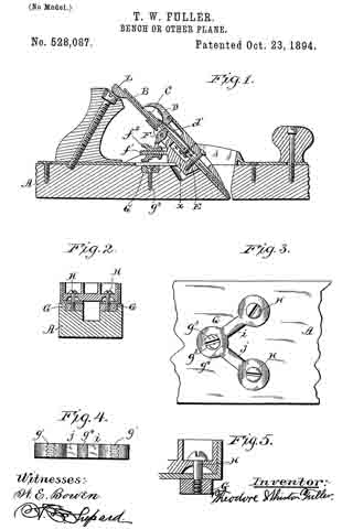
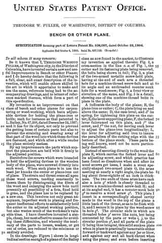
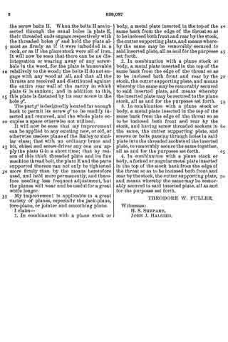
In the drawings: Figure 1 shows in longitudinal section enough of a plane of the Bailey class as now found in the market, to illustrate my invention as applied thereto; Fig. 2, a cross-section in the line x x of Fig. 1, the cutter and its fastening plate being removed, the bolts being shown in full; Fig. 3, a plan of the two-armed metallic screw-held plate, having at the end of each arm a threaded hole for a machine-thread screw-bolt and at its angle end an unthreaded counter sunk hole for a wood-screw; Fig. 4, a front view or elevation of the same, and Fig. 5 is a detail, showing one of the machine-thread bolts in place in the plate.
A indicates the body of the plane; B, the plane-iron or cutter; C, the plate lying on and above the same; D, the cam-lever, and d’ its spring, for tightening this plate on the cutter; E, the lever supporting plate; F, the forked lever fulcrumed on this plate, and f’ the screw, and f2 the nut, for moving such lever to adjust the plane-iron longitudinally; L, the lever for adjusting said iron to insure the parallelism of the cutting edge with the bottom of the plane stock. These parts being well known, need not be more particularly described.
Instead of securing directly to the wood the plate E, which carries the forked lever and its adjusting screw, and which practice has been found so disastrous when and after its wood screws get loose, I make a stout specially-shaped two-armed plate G, the arms meeting at nearly a right angle, the plate being about three-eighths of an inch in thickness. The two ends of these arms have each also a hole g’ which is closely threaded to receive a machine-thread screw-bolt H; and at its angled end, it has a counter-sunk hole g2 to receive a wood screw g3. This plate I insert in a correspondingly shaped cavity made in the wood in the top of the plane a little back of the throat, so as to be tlush with it, and I secure it in place by the wood-screw in hole g2. The circular ends in which are threaded holes g’ serve like nuts, but being connected by the parts or webs i, j, to the circular portion g4, and all parts of the plate G being thus integral, this solid sunken plate when in place is practically immovable either forward or backward against any jar or blow, and against any and all back-thrust when using the plane; and even before inserting the screw bolts H. When the bolts H are inserted through the usual holes in plate E, their threaded ends engage respectively with the threaded holes g’ and hold the plate almost as firmly as if it were imbedded in a rock, or as if the plane stock were all of iron. It will now be seen that there can be no disintegration or wearing away of any screw-hole in the wood, for the plate is immovable relatively to the wood; the bolts H do not engage with any wood at all, and that all the thrusts are received and distributed against the entire rear wall of the cavity in which plate G is sunken; and in addition to this, this plate is fastened by its rear screw in the hole g2.
The part g4 is designedly located far enough back to permit its screw g2 to be readily inserted and removed, and the whole plate occupies a space otherwise not utilized.
It will now be seen that my improvement can be applied to any existing new, or old, or otherwise useless plane of the Bailey or similar class; that with an ordinary brace and bit, chisel and screw-driver any one can apply the plate G in a short time; that by reason of this thick threaded plate and its fine machine thread bolt, the plate E and the parts supported thereon can not only be tightened more firmly than by the means heretofore used, and held more permanently, and therefore needing less frequent adjustment, but the planes will wear and be useful for a great while longer.
My improvement is applicable to a great variety of planes, especially the jack-plane, fore-plane, or jointer and smoothing plane.
I claim —
1. In combination with a plane stock or body, a metal plate inserted in the top of the same back from the edge of the throat so as to be in closed both front and rear by the stock, the cutter supporting plate, and means whereby the same may be removably secured to said inserted plate, all as and for the purposes set forth.
2. In combination with a plane stock or body, a metal plate inserted in the top of the same back from the edge of the throat so as to be inclosed both front and rear by the stock, the cutter supporting plate, and means whereby the same may be removably secured to said inserted plate, and means whereby the inserted plate may be secured to the plane stock, all as and for the purposes set forth.
3. In combination with a plane stock or body, a metal plate inserted in the top of the same back from the edge of the throat so as to be inclosed both front and rear by the stock, and having screw threaded sockets in the same, the cutter supporting plate, and screws or bolts passing through holes in said plate into the threaded sockets of the inserted plate, to removably secure the same together, all as and for the purposes set forth.
4. In combination with a plane stock or body, a forked or angular metal plate inserted in the top of the stock back from the edge of the throat so as to be inclosed both front and rear by the stock, the cutter supporting plate, and means whereby the same may be removably secured to said inserted plate, all as and for the purposes set forth.
THEODORE W. FULLER.
Witnesses:
H. S. SHEPARD,
JOHN J. HALSTED.