No. 17,951 – Joiner’s Plane (Thomas D. Worrall) (1857)
UNITED STATES PATENT OFFICE.
_________________
THOS. D. WORRALL, OF LOWELL, MASSACHUSETTS.
JOINER’S PLANE.
_________________
Specification of Letters Patent No. 17,951, dated August 4, 1857.
_________________
To all whom it may concern:
Be it known that I, THOS. D. WORRALL, of Lowell, Massachusetts, have invented certain new and useful Improvements in Planes; and I do hereby declare that the following is a full, clear, and exact description of the same, reference being had to the accompanying drawings and to the letters of reference marked thereon.
The nature of my invention consists in certain devices for securing and regulating the bits in planes, the peculiarities of which will be hereinafter fully described.
In order that others skilled in the art may manufacture and use my invention I will proceed to describe its construction and operation.
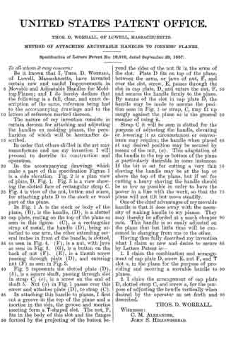
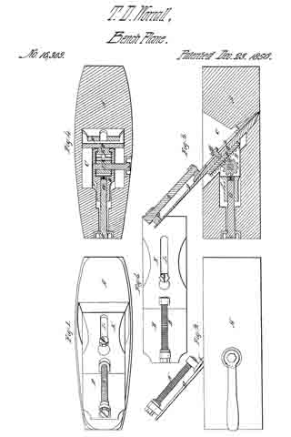
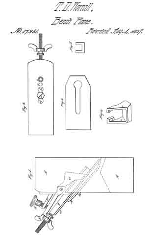
In the accompanying drawings which make a part of this specification Figure 1 is a side elevation showing its internal arrangement in dotted lin. Fig. 2 is a plan view of the bit. Fig. 3 is a view of the cap. Fig. 4 is a perspective view of the bottom of the clamp lever. Fig. 5 is a top view of said lever.
In Fig. 1 (A) is the body or stock of the plane. B is a strap attached to the back of the bit — having a screw in its upper extremity — its lower extremity being in the form of a T. (G) is the bit secured to the T strap by means of screws (n n’) seen in Fig. 2. H is the cap having a slot in it as seen in Fig. 3, and secured to the bit by means of a screw (m), said cap being concave as seen in Fig. 1. (D) is a rest attached to the top of the plane. (C) is a clamp lever, being pivoted at (i) and having a slot in its upper extremity (o) seen in this figure being one of the arms of said slot. (F) is a nut, working on the screw on the end of T strap (B), said nut having a groove in it, the groove fitting in the slot on the end of lever C. (E) is a screw passing through rest (D) and serving to operate lever (C).
Fig. 2 represents the bit, (n, n) being screws through it for the purpose of adjusting the T strap, as the plane bit wears. As the bit wears away the screws (n’ and n) may be removed; also, screws (m). Then after slipping the bit down (n’) will enter the place occupied by (n). (n) will occupy hole (x) and m will occupy the hole (n). In this manner I may use a suflicient number of holes and wear the bit entirely up, which cannot be done in the ordinary plane secured with strap.
Fig. 4 shows the bottom of clamp lever C — the T arms of lever C slip in between jaws (a) and slide on flanges (c), being clamped by said flanges when the lever is operated above by means of screw (E).
Fig. 5 shows a top view of the clamp lever with its slot for receiving the tap or nut (F).
In operating this plane the bit is first secured to the T strap, then the cap may be adjusted to its proper position on the bit, and the strap inserted into position in the plane stock — the lower extremity of the T strap enters the jaws of clamp lever C and its arms slide on, and are secured by flanges (c) — the groove in nut (F) being adjusted in slot into top of lever C the screw (E) is operated and the bit firmly secured.
The advantages of clamp lever C are very readily perceived (the lever may be made any desired or convenient length and the power obtained by it may be very great) for there is no known process by which a plane bit may be so securely bedded as by this — this lever operates upon the bit at two important points for bedding it — it draws the bit in at the bottom, with the power, and in a manner that can be done by no other means. The easy adjustment of the plane by means of lever C and screw (E) gives it advantages not possessed by other planes.
Having thus fully described my invention what I claim as new and desire to secure by Letters Patent is —
I claim —
The employment of the clamp lever C for securing and bedding the bit, in the manner herein fully set forth and described.
In testimony whereof I hereunto set my hand.
THOS. D. WORRALL.
Witnesses:
C. M. ALEXANDER,
JOHNS HOLLINGSHEAD.