No. 1,393,991 – Plane (John M. Dodenhof) (1921)
[paiddownloads id=”729″]1393991


UNITED STATES PATENT OFFICE.

_________________

JOHN H. DODENHOF, OF ST. LOUIS, MISSOURI.

PLANE.

_________________

1,393,991. Specification of Letters Patent. Patented Oct. 18, 1921.
Application filed September 24, 1920. Serial No. 412,431.

_________________

To all whom it may concern:

Be it known that I, JOHN M. DODENHOF a citizen of the United States, residing at St. Louis, in the county of St. Louis and State of Missouri, have invented certain new and useful Improvements in Planes, of which the following is a specification.

This invention relates to planes for dove-tailing tongue and grooving, dado work and the like, and the primary object of the invention is to provide an improved attachment for planes of this character, which is so constructed that dove tail tongue and grooving can be cut at any angle in an expeditious and simple manner.

Another object of the present invention is to provide an improved guide for dove tail tongue and grooving work and the like, which will hold the plane and its cutting blade at the correct and desired angle, the guide being so arranged and associated with the main stock of the plane in such a manner as to permit the same to be swung at any angle and at any distance from the main stock.

A still further object of the invention is to provide an improved sliding section for the main stock of the plane, so as to permit various sizes and shapes of cutting blades to be used with the plane, the sliding section being formed in separate pieces which are adjustable toward and away from the work, and toward the main stock.

A still further object of the invention is to provide an improved attachment for planes of the above character, which will be durable and efficient in use, one that will be simple and easy to manufacture, and one which can be placed upon the market and associated witii planes at a reasonable cost.

With these and other objects in view, the invention consists in the novel construction, arrangement and formation of parts as will be hereinafter more specifically described, claimed and illustrated in the accompanying drawings, forming a part of this specification, in which drawings:

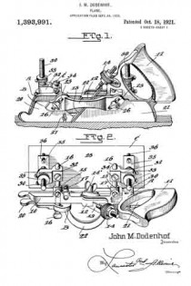
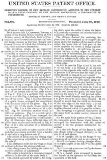
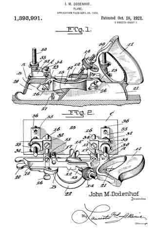
Figure 1 is a side elevation of the improved plane showing the same in use, the work being shown in longitudinal section.

Fig. 2 is a top plan view of the plane and its attachment.

Fig. 3 is a front elevation of the plane and its attachment showing the use of the same for making dove tail grooves, the work being shown in transverse section.

Fig. 4 is a fragmentary side elevation of the plane and attachment looking in the opposite direction from Fig. 1, illustrating the position of the plane and attachment when in use, the work being shown in section, and

Fig. 5 is a detail transverse section taken through the main stock and sliding section illustrating the means of adjustably connecting the sliding section with the main stock.

Referring to the drawings in detail, wherein similar reference characters designate corresponding parts throughout the several views, the letter A indicates the plane, B, its sliding section, and C, the improved adjustable guide therefor.

The plane A may be of the usual or any preferred form and of any desired make, or of the type utilized for making dove tails, tongue and grooving, dado work and the like. As shown the plane A includes the main stock 10 having the handle 11 arranged on one end of the same. The main stock 10 is provided with the usual cutting blade or tool guide 12 for the tool or blade 13. As shown the guide is arranged at an angle to the vertical in the usual manner and is provided with the usual holding blade nut and bolt 14’. As shown the bolt extends transversely of the stock. The handle 11 supports at its forward end the usual adjusting device 14, which may be of any preferred construction. The main stock 10 is provided with the straight laterally extending hollow bosses 15, which slidably support the guide arms 16, which are held in their preferred adjusted positions by means of set screws or the like 17. These arms 16 may be of any preferred length and are utilized for supporting the sliding section B and the improved attachment C.

The improved sliding section B of the plane is constructed similar to the usual sliding sections for planes of this character, with the exception that the same is constructed in three sections, namely, the forward body section 20, the rear body section 21 and the connecting bridge piece 22. The body sections 20 and 21 are formed of any preferred material and are in direct vertical alinement with each other and are adapted to receive between the same the cutting blades or tools which are carried by the main stock 10. The forward edge of the body piece 21 of the sliding section B is inclined to conform to the inclination of the guide 12 for the cutting tool or blade.

The bridge piece 22 may be connected to the body sections 20 and 21 in any preferred manner, and if so desired the terminals thereof may be welded or brazed to the body section. As shown the bridge piece 22 is substantially arcuate shaped in plan and is so shaped as to permit blades or cutting tools of various widths to be used. The body pieces 20 and 21 are provided with inclined guide slots 23, which slidably receive the flattened or polygonal shaped terminals 25 of the guide arms 16. It can be seen that the slidin section B may be raised or lowered according to the depth of the groove, tongue or the like being made. To hold the sliding section B in its adjusted position, the flattened or polygonal shaped terminals 25 of the guide arms 16 are provided with threaded bores for the set screws 26 which are adapted to frictionally engage the outer surface of the sliding section B. If so desired the sliding section B may be provided with the swinging spur 27 for cross grain work.

The improved attachment or side section C includes the flat rectangular shaped plate or bottom 28, which is adapted to engage the work and hold the main stock 10 with its cutting blade or tool at the desired angle for making the desired dove tail groove or tongue. The upper surface of the base plate or bottom 28 is provided adjacent to its opposite ends with the upstanding ears 29 which are connected to the lower terminals of the adjusting screw threaded stems 30 by means of pivot ins or the like 31. These screw threaded adjusting stems 30 are slidably carried by blocks 32 which are provided with transverse bores for the reception of the guide arms 16. It can be seen by referring to Fig. 2 of the drawings that the blocks 32 project laterally from the guide arms 16 and are adjustably mounted thereon toward or away from the main stock 10. These blocks are held in their adjusted positions on the guide arms by means of set screws or the like 34. It is to be also noted that not only are the guide arms themselves adjustable but that the blocks 32 are adjustably mounted thereon.

The screw threaded guide stems 30 are, as stated, slidably carried by the blocks 32 and these stems are held in their adjusted positions by means of upper and lower lock nuts 33 which are threaded on the stems into engagement with the opposite sides of the blocks. The lower terminals of the stems 30 are provided with the outwardly extending rigid plates 35, which adjustably support the screw threaded members 36, which are adapted to engage the upper surface of the guide plate or bottom 28 for holding the same at the desired angle in relation to the main stock 10 of the plane A. These screws 36 are held in their adjusted position by means of nuts 37 which are threaded thereon into engagement with the plates 35.

In operation of the plane and guide, the desired tool or cutting blade is placed in the guide 12 in the usual manner and the blade or tool is adjusted by means of the device 14. The sliding section B is then adjusted toward the blade by means of the sliding arms 16 until the section is at the desired point. The guide plate or bottom 28 is then slid on the guide arms 16 to the desired point and held in place by means of the set screws 34 provided for that purpose, after which the plate or bottom 28 is swung to the desired angle at which the dove tail grooves or tongues are to be made on the pivot pins 31, after which the set screws 36 are adjusted so as to hold the plates or bottoms in this position. The plate or bottom engaging the work will effectively hold the main stock 10 and its cutting blade at the desired angle and the dove tail will be made with the desired inclination to the walls thereof. The depth of the groove to be made can be determined by the distance on the plate 28 from the tool and this distance can be varied as desired by means of the threaded stem 30. If so desired, the position of the plate 28 can be changed from one side to the other to suit varying conditions.

The plane, if so desired, can also be used with the usual sliding section and fence (not shown) for rabbeting or the like, but the same forms no part of this invention.

Changes in details may be made without departing from the spirit or scope of this invention; but, I claim:

1. In a plane, the combination with a main stock, a sliding section adjustably carried by the main stock and arranged in parallel relation to the main stock, a cutting blade arranged between the sliding section and the main stock, of a guide including a laterally projecting pivoted plate arranged to turn both in a plane at right angles to the stock and in a plane parallel to the stock and sliding section, and means for varying the angle of the plate in relation to the main stock, sliding section and blade.

2. In a plane, the combination with a main stock, a sliding section adjustably carried by the main stock and arranged in spaced parallel relation thereto, a cutting blade arranged between the main stock and sliding section, of a guide including a laterally projecting plate adjustably toward and away from the main stock, means pivotally securing the plate in position to permit the same to turn both in a lane at right angles to the stock and sliding section and in a plane parallel to the stock and section, means for raising and lowering the plate in relation to the stock, and means for varying the angle of the plate in relation to the stock.

3. In a plane, the combination with a main stock, a sliding section adjustably carried by the main stock, a cutting blade arranged between the main stock and sliding section, of a guide including a laterally projecting substantially rectangular shaped plate, means pivotally securing the plate in position to permit the same to turn both in a plane parallel to the stock and sliding section and in a plane at an angle to the stock and sliding section, means for adjusting the height of the plate in relation to the main stock, sliding section and blade, and means for varying the angle of the plate in relation to the stock.

4. In a plane, the combination with a main stock, a pair of sliding guide arms carried by the stock, means for holding the guide arms in adjusted position, a sliding section adjustably carried by the guide arm, means for holding the sliding section in adjusted position, a cutting blade arranged intermediate the sliding section and main stock, of a guide including a pair of blocks adjustably mounted on the guide arm, threaded stems slidably carried by the blocks, means for holding the threaded stems in adjusted position in relation to the blocks, a substantially rectangular shaped flat plate pivotally carried by the lower ends of the stems, and means for holding the plate in adjusted position in relation to the stems.

5. As a new article of manufacture, a guide for bench planes comprising a flat plate, a pair of pivoted stems carried by the upper surface of the plate, blocks adjustably carried by the stems, means for holding the stems and the blocks in adjusted relation to each other, laterally projecting plates rigidly carried by the stems adjacent to their lower ends, adjustable set screws carried by the laterally projecting plates arranged to engage the upper surface of the first mentioned plate, the blocks having transversely extending bores therein, and set screws carried by the blocks arranged to extend into said bores.

JOHN M. DODENHOF.

No. 1,042,139 – Tongue-And-Groove Plane (Albert A. Page) (1912)

[paiddownloads id=”685″]1042139


UNITED STATES PATENT OFFICE.

_________________

ALBERT A. PAGE, OF NEW HAVEN, CONNECTICUT, ASSIGNOR TO SARGENT & COMPANY,
OF NEW HAVEN, CONNECTICUT, A CORPORATION OF CONNECTICUT.

TONGUE-AND-GROOVE PLANE.

_________________

1,042,139. Specification of Letters Patent. Patented Oct. 22, 1912.
Application filed September 23, 1911. Serial No. 650,904.

_________________

To all whom it may concern:

Be it known that I, ALBERT A. PAGE, a citizen of the United States, residing in the city and county of New Haven, State of Connecticut, have invented new and useful Improvements in Tongue-and-Groove Planes, of which the following is a full, clear, and exact description when taken in connection with the accompanying drawings.

My invention relates to reversible or invertible tongue and groove planes, and the primary object of the invention is to provide a tool of this sort which is practically as handy and convenient in use as the well known tongue cutting planes and grooving planes in which the tongue cutting function and the groove cutting function are not combined.

It is also aimed to produce a plane of this kind which is not only handy and well balanced but also of comparatively light, simple and inexpensive construction. The main advantage of the improved tool resides, however, in the fact that it provides a very convenient and satisfactory grip for the workman, whether used for tongue cutting or grooving, and that it is peculiarly compact, and has the respective cutters so arranged as to do the most effective work.

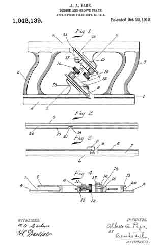
In these drawings, Figure 1 is a side elevation of the plane; Fig. 2, a plan view of the edge adapted to fit the groove; Fig. 3, a plan view of the edge adapted to form and engage the tongue; and Fig. 4, a cross section on the line x–x of Fig. 1.

In all figures, similar letters of reference represent like parts.

Referring to the drawing, the open skeleton frame constituting the stock is shown at 1. This frame comprises parallel lower and upper edge portions 4, 5, of which the former acts as a bearing surface when cutting the tongue, while the latter serves as a bearing surface in cutting the groove. These parallel bearing portions of the skeleton frame are connected at the ends of the plane, preferably in an integral manner, by handle or grip portions 2, 3, respectively. These handle or grip portions, while slightly curved in a longitudinal direction and of appropriate cross-section, in order to form a convenient and satisfactory grip for the hand of the workman, are generally parallel with respect to each other and form, in connection with the parallel bearing portions, 4, 5, a stock of substantially rhomboidal shape.

Projecting inwardly from the respective bearing portions 4, 5, are lugs or brackets 13 and 15 respectively against which the respective bits 8 and 14: are positioned. The supporting brackets or lugs 13 and 15 are preferably formed integrally with the bearing portions 4 and 5 and are equipped with flat bearing surfaces for the bits, which bearing surfaces are directed parallel to each other and substantially parallel with one of the diagonals of the rhomboidal figure formed by the intermediate open space between the handles 2 and 3. By placing the supporting brackets and the bits in superposed relation, as shown, with one bracket and its bit placed oppositely with respect to the other bracket and bit as regards the diagonal aforesaid, it is possible to shorten the plane materially while still providing for the location of the cutting edges of the respective bits at the proper distances from the respective ends of the plane. In other words, by this construction I am enabled to provide an efficient plane of minimum length wherein the distance from each cutter to one end of the plane bears such a ratio to the distance from said cutter to the other end of the plane that the bearing portions 4, 5, coact properly and effectively with the respective bits.

The bearing portion 4 is provided at one side with a relatively short depending flange 6 creating a groove 7 into which projects the tongue cutting bit 8, the cutting end of which is recessed at 9 in order to form the tongue in well known manner. The bit 8 is positioned relatively to its support 13 by means of a lever pivoted at 12 and bearing against the bit at one end, while the opposite end carries a clamping screw 10 coacting with the bit in well known manner. The bearing portion 5 is provided with a groove 20 and with a flange 19 alined with the cutting edge 21 of the bit or cutter 14. This bit or cutter is positioned relatively to its support 15 by means of a lever 16 pivoted at 17 and having a clamping screw 18.

The operation of the device is as follows: When it is employed for forming and planing the tongue in the edge of the work, the latter is engaged with the groove 7 and the grip member 2 engaged by the hand of the operator. In the operation of the device in this position the slot 9 will leave a central unplaned space on the edge of the board of the desired width of the tongue and in the continued movement of the plane the portions on either side of this space will be planed down so as to form a tongue of the proper width. After the tongue has been formed it is merely necessary to reverse the plane edge for edge and grasp the grip member 3 by the hand and apply the rib 19 to the opposite edge of the board or edge of another board, and then operate the plane for the purpose of forming the groove, the cutter 21 engaging said edge and forming the groove.

By forming the plane of substantially rhomboidal shape a most satisfactory grip may be afforded by the handles 2 and 3. By locating the bits and bit supports in the manner described the construction of the tool is simplified and its expense lowered, and in addition to this, the tool is made light and well balanced, and is especially effective in operation.

Having thus described my invention, what I claim and desire to secure by Letters Patent, is :–

l. An invertible or reversible tongue and groove plane comprising parallel oppositely located bearing portions, handle members joining the respective ends of the respective bearing portions and forming in conjunction with said bearing portions a skeleton frame or stock of substantially rhomboidal form, separate bit supports projecting from the respective bearing portions into the inner open portion of the frame or stock, said bit supports being arranged in superposed relation and having bearing surfaces directed substantially parallel to one of the diagonals of the rhomboidal opening of the frame or stock, and bits clamped on the respective bearing surfaces and cooperating with the respective bearing portions; substantially as described.

2. An invertible or reversible tongue and groove plane comprising parallel oppositely located bearing portions, handle members joining the respective ends of said bearing portions and forming in conjunction therewith a skeleton frame or stock of approximately rhomboidal form, bit supports formed integrally with the respective bearing portions and extending therefrom into the inner open portion of the frame or stock, and bits clamped on the respective bit supports, substantially as described.

3. ln an invertible or reversible tongue and groove plane, an open skeleton frame formed of oppositely arranged parallel bear-
ing portions and handle members connecting the respective bearing portions at the ends of the plane, approximately parallel bit supports extending inward from the respective bearing portions into the inner opening of the frame, said bit supports being arranged in superposed relation and having their bit supporting surfaces opposing or facing each other, and bits clamped on said surfaces and cooperating with the respective bearing portions, substantially as described.

ln witness whereof, I have hereunto set my hand on the 21st day of September, 1911.

ALBERT A. PAGE.

Witnesses:
HENRY H. MUNSON,
CARL W. CARLSON.

_________________

Copies of this patent may be obtained for five cents each, by addressing the “Commissioner of Patents, Washington, D. C.”
_________________

No. 962,885 – Dovetail Tongue And Groove Cutter (Christian Bodmer) (1910)

No. 962,885 – Dovetail Tongue And Groove Cutter (Christian Bodmer) (1910)

[paiddownloads id=”672″]962885


UNITED STATES PATENT OFFICE.

_________________

CHRISTIAN BODMER, OF NEW BRITAIN, CONNECTICUT, ASSIGNOR TO THE STANLEY RULE
& LEVEL COMPANY, OF NEW BRITAIN, CONNECTICUT, A CORPORATION OF CONNECTICUT.

DOVETAIL TONGUE AND GROOVE CUTTER.

_________________

962,885. Specification of Letters Patent. Patented June 28, 1910.
Application filed November 26, 1909. Serial No. 529,864.

_________________

To all whom it may concern:

Be it known that I, CHRISTIAN BODMER, a citizen of the United States, residing at New Britain, county of Hartford, State of Connecticut, have invented certain new and useful Iinprovements in Dovetail Tongue and Groove Cutters, of which the following is a full, clear, and exact description.

My invention relates to an improved means in the nature of a plane for forming dovetailed or undercut tongues and grooves.

The object of the invention is to provide a means for performing the above function which shall be so constructed as to permit the forming of such tongues or grooves with the greatest facility and accuracy.

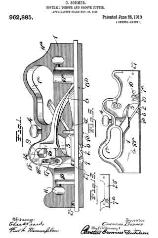
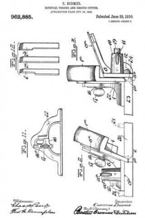
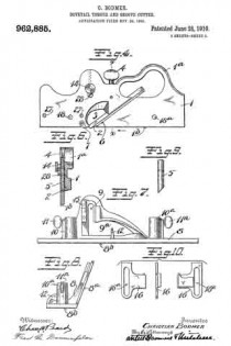
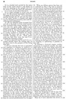
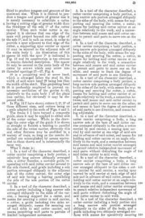
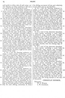
In the drawings, Figure 1 is a side elevation of the tool assembled and adjusted for the purpose of forming an undercut groove. Fig. 2 is a rear end elevation of Fig. 1, showing the tool as it appears in the act of forming a groove. Fig. 3 is an end elevation of the tool assembled and adjusted for the purpose of cutting a tongue. Fig. 4 is a side elevation of the main body and certain parts on a somewhat reduced scale. Fig. 5 is a view of the reverse side of the parts shown in Fig. 4. Fig. 6 is a sectional view on the line x–x of the Fig. 4, looking in the direction of the arrow. Fig. 7 is a side elevation of a guide frame, arranged for association with the main body of the plane. Fig. 8 is an end view of the guide frame shown in Fig. 7. Fig. 9 is a side elevation of a detail. Fig. 10 illustrates another detail in diderent positions. Fig. 11 is a side elevation of another guide frame arranged for association with the main body of the plane. Fig. 12 illustrates three different sizes of plane irons, on the scale indicated in Fig. 4. Fig. 13 is a side elevation of a detachable spur carrier.

1 is the main body or cutter carrier of the tool, the same being provided with a handle 1a and with a long narrow sole 1b.

2 is a cutter or plane iron, the cutting edge of the same being adjustable in a throat in the sole 1b.

3 is a clearance outlet for shavings or chips and located above the aforesaid throat.

4 is a clamp screw for locking the cutter in various positions of adjustment.

The cutter is located in a channel arranged obliquely in the side of the main body 1.

5 is a clutch operated by screw 4, for wedging down upon the cutter 2 when the latter is in position to prevent its unintentional or accidental dislodgment.

The oblique channel for receiving the plane iron is so arranged as to support the upper and lower surface of the shank of the cutter, the lower side of that part of the cutter opposite the recess 3 being supported on the incline 6. As will later be seen, cutters having cutting edges of different widths may be substituted, but to secure the best results the shank portion of each cutter should be substantially alike, the variations in sizes occurring at and directly above the cutting edge.

As will be seen by Figs. 2 and 3, the sole 1b of the body 1 is formed at an oblique angle to the opposite side walls thereof and in practice it is obvious that the edge of the cutter should be shaped to correspond.

7–7a are spurs arranged on opposite sides of the main body 1, both spurs being arranged to be projected to any desired degree or to be entirely retracted as desired. The function of said spurs is to score the wood in advance of the cutter 2, whereby, when said tool is used across the grain, the score lines made by the spurs 7–7a will prevent splintering the wood, thereby enabling the cutter 2 to plow out or to cut a clean channel. It should be stated that the width or thickness of the sole edge of the main body 1 is not greater than the minimum width of the smallest channel which it is possible to form.

The foregoing is a general description of the main body or cutter carrier element of the tool.

8 is the main body portion of what I term the composite guide frame, which frame is arranged for association with the cutter carrier 1 for the purpose hereinafter described.

8a is the side flange of the frame 8, said side flange being arranged obliquely to the sole 8b of said frame.

9 is an upright slot in the fiange 8a terminating at its lower end in an opening 9a.

10–10a are bosses, having passages therein at right angles to the sole 8b of the guide frame 8.

11–11a are set screws carried by the bosses 10–10a respectively.

12 is a thumb piece arranged to receive the thumb of the operator to facilitate the operation of the tool.

14 is a headed stud carried by the main body of the cutter carrier 1, the shank of said stud standing in the upright slot 9 of the frame 8 when the parts are assembled.

15 is a scale at one side of the slot 9.

16 is a gage arranged to co-act with the scale for the purpose hereinafter described. The gage 16 has a slot 16a. 17 is a set screw passing through slot 16a and into the body of the cutter carrier 1, whereby said gage may be adjusted up and down, said scale facilitating said adjustment.

18–18a are threaded holes arranged fore and aft in the body 1 of the cutter carrier, these threaded holes being arranged to receive the two guide posts, spaced apart properly to register with the sockets 10–10a of the guide 8. One of these guide posts is shown at 19, Fig. 3. These guide posts may be readily applied or removed by simply turning the screw end of each into the threaded openings 18–18a. These guide posts are used only when the tool is asembled for forming a tongue.

It will be observed that the stud 14 is arranged directly above the cutting edge of the plane iron 2, the purpose of this being later seen.

I will now describe the tool as assembled and employed in forming an undercut or dovetail groove. In this connection particular reference is directed to Figs. 1 and 2. In these figures it will be seen that the cutter carrier 1 is combined with the guide frame 8 and it may be assumed that the gage 16 is secured by the screw 17 on the scale 15 at the proper elevation to limit the depth of the cut. The intention now is to form a dove-tail groove in a piece of wood indicated at 20 (Fig. 2). To do this, the location of the groove is determined and a guide cleat 21 is tacked down to said piece of wood in a line parallel to the groove to be formed, and at one side thereof a distance corresponding to the width of the bottom of the sole 8b of the guide frame 8. The tool is then placed in the position indicated in Fig. 2 bearing against the cleat 21 and is moved to and fro until the cutter has descended into the wood 20 to the desired depth determined by stop 16. In forming this cut, both spurs 7–7a should be turned down, particularly if cut is to be made across the grain. The cutter carrier 1, being connected to the guide frame 8 only by the stud 14, may take an oscillating movement relatively to the guide frame 8 and hence may follow any warped portion of the wood in which the cut is being formed. By reason of the location of the stud connection 14 relatively to the cutter 2, the oscillating movement of the carrier relatively to the guide frame will not permit the cutter 2 to descend into any part of the wood 20 more than the amount predetermined by the gage 16. When an oblique groove has been cut as indicated in Fig. 2 the tool is removed and the cleat 21 is taken off and tacked down on the opposite side of the groove as indicated in dotted lines, being spaced apart from the adjacent edge to be of the groove a distance corresponding to the width of the bottom of sole 8a of the guide frame. The instrument is then turned around and operated as first described, the cutter 2 working down in the wood until the balance of the intended dove-tail groove is formed, as indicated in the dotted lines, Fig. 2. In forming this last part of the groove, it is unnecessary to employ the spur 7a which may be turned back into the position shown in Fig. 5, a recess in the said main body 1 receiving the same, so that it will stand flush, the spurs themselves being held in all positions by ordinary machine screws. The spur 7a will be seen to be unnecessary at this time because as the cutter descends, the wood on that side of the plane iron (the side toward the spur 7a) has previously been cut away in forming the first part of the groove, hence no chipping or splintering is possible on that side.

In forming a dove-tail tongue, another adjustment is employed, namely, the right angle guide 22, the same being substituted in the place formerly occupied by the guide 8, which latter is transferred to the opposite side of the frame 1 (as shown in Fig. 3) and mounted upon the posts 19–19, the sole 8b of the said guide 8, being spaced apart from the opposite side of the cutter carrier 1, a distance corresponding to the depth of the tongue to be formed. 23 represents the piece of wood upon which the dove-tail tongue is to be formed, said tongue portion being indicated at 24. The gage 16 is now adjusted on the scale 15 to such a position as to properly limit the descent of the cutter carrier 1. The instrument is placed in the position indicated in the Fig. 3, and moved to and fro. The right angle guide 22 cooperates with the guide 8 in holding the cutter carrier 1 in the proper position to cause the cutter to enter the wood as shown in Fig. 3, in which one-half of the tongue is represented as completed. In performing this work, the guide 8 obviates the use of a batten such as 21, although the latter could be used if desirable. To form the other half of the tongue 24 (indicated by dotted lines), the piece of wood 23 is simply turned over and the tool is used on the opposite surface in the same manner. In the formation of the tongue only one spur need be employed, namely the spur 7.

From the foregoing it will be seen that a dove-tail groove and a tongue of corresponding size and cross section may be formed with the greatest accuracy and ease.

Thus far I have described the device as fitted to produce tongues and grooves of the minimum size. When it is desired to produce a tongue and groove of greater size it is merely necessary to substitute a cutter having a cutting edge of greater width than the thickness of the sole 1b of the cutter carrier. When such wider cutter is employed it is obvious that one edge of the same will project beyond one side edge of the sole 1b, and in such an event, in order to provide a spur adjacent to that edge of the cutter, a supporting spur carrier or spacer 25 may be secured to the adjacent side of the main body 1. An illustration of this spacer 25 with the spur 7a is indicated in Fig. 13 and its construction is too obvious to require detailed description. The spacer 25 may be secured to the main body of the cutter by screws which may screw into threaded openings 27–27, Fig. 4.

28 is a projecting stud or screw head, which is arranged below the stud 14, the width of said screw head 28 being less than the width of the slot 9. This projecting head 28 is preferably employed to prevent unnecessary oscillation of the guides 8–22, relatively to the main body 1 of the plane iron carrier, but obviously it may be dispensed with.

In Fig. 12 I have shown cutters 2, 2a, 2b of three different sizes, said cutters being on a scale adapted to the scale of Figs. 4 and 5.

The frame 8 I have termed a composite guide, since it may be applied to either side of the cutter carrier. While in the drawings the outer edge of the guide 8 is shown as straight to furnish a bearing to parallel the sole of the cutter carrier, obviously this and other features may be modified in a variety of ways, so long as the results described are accomplished by means equivalent to those shown and in substantially the same way.

What I claim is:

1. In a tool of the character described, a cutter carrier comprising a body portion, a relatively long narrow obliquely arranged sole, a cutter therefor, a movable guide cooperating with said cutter carrier secured to the side thereof, said guide including a sole portion arranged obliquely to the adjacent side of the cutter carrier, the outer edge of said sole having a bearing paralleling the side of the sole portion of the cutter carrier.

2. In a tool of the character described, a cutter carrier including a long narrow sole arranged obliquely to the sides of the carrier, a bearing support for a cutter, and means for securing a cutter in said carrier, a cutter, a guide including two sides arranged obliquely, means for securing one of said sides to said cutter carrier, said means permitting said parts to partake of limited independent movement.

3. In a tool of the character described, a cutter carrier comprising a body portion, a long narrow sole portion arranged obliquely to the sides of the body, with means for supporting and securing the cutter, a cutter, means for holding said cutter carrier at an angle relatively to the work, and a connection between said means and said cutter carrier to permit said parts to move one on the other.

4. In a tool of the character described, a cutter carrier comprising a body portion, a long narrow sole portion arranged obliquely to the sides of the body, with means for supporting and securing the cutter, a cutter, means for holding said cutter carrier at an angle relatively to the work, a connection between said means and said cutter carrier to permit said parts to move one on the other, and means to limit the degree of movement of said parts in one direction.

5. In a tool of the character described, a cutter carrier comprising a body portion, a long narrow sole portion arranged obliquely to the sides of the body, with means for supporting and securing the cutter, a cutter, means for holding said cutter carrier at an angle relatively to the work, a connection between said means and said cutter carrier to permit said parts to move one on the other, and means to limit the degree of movement of said parts in one direction, said means being adjustable.

6. in a tool of the character described, a cutter carrier comprising a body, a long narrow sole at the base of said cutter carrier arranged obliquely to the sides, a cutter carried by said carrier, a scoring spur carried by said carrier at one edge of said sole and in advance of said cutter, and means for holding said cutter carrier at an angle relatively to the work, and a connection between said means and said cutter carrier arranged to permit relative independent movement of said parts without disturbing the angle of said cutter carrier to said work.

7. In a tool of the character described, a cutter carrier comprising a body, a long narrow sole at the base of said cutter carrier arranged obliquely to the sides, a cutter carried by said carrier, a scoring spur carried by said carrier at each edge of said sole and in advance of said cutter, means for holding said cutter carrier at an angle relatively to the work, and a connection between said means and said cutter carrier arranged to permit relative independent movement of said parts without disturbing the angle of said cutter carrier to said work.

8. In a tool of the character described, a cutter carrier including a body portion and a long narrow sole portion arranged obliquely to the sides of the body, and a guide including two obliquely arranged surfaces with means for operatively securing said guide to either side of said cutter carrier whereby in either position it will serve as a guide in the performing of work.

9. In a tool of the character described, a cutter carrier including a body portion and a long narrow sole portion arranged obliquely to the sides of the body, a guide including two obliquely arranged surfaces with means for operatively securing said guide to either side of said cutter carrier whereby in either position it will serve as a guide in the performing of work, and a second guide having right angle faces arranged under certain conditions to cooperate with said cutter carrier and the first mentioned guide.

10. In a tool of the character described, a cutter carrier including a body portion and a. long narrow sole portion arranged obliquely to the sides of the body, a guide including two obliquely arranged surfaces with means for operatively securing said guide to either side of said cutter carrier whereby in either position it will serve as a guide in the performing of work, and a second guide having right angle faces arranged under certain conditions to cooperate with said cutter carrier and the first mentioned guide, with means for permitting relative independent movement between said cutter carrier and said second guide without disturbing the operative angle of the cutter carrier to the work.

11. In a tool for forming undercut recesses, a cutter carrier comprising a main body and a relatively long narrow sole arranged obliquely to the sides of said body, a cutter carried by said carrier, a guide for said carrier, a sliding connection between said guide and carrier, a sole on said guide arranged obliquely to the side of said carrier when the parts are assembled in operative position, and a side bearing at the outer edge of said sole portion.

12. In a tool for forming undercut recesses, a cutter carrier comprising a main body and a relatively long narrow sole arranged obliquely to the sides of said body, a cutter carried by said carrier, a guide tor said carrier, a sliding connection between said guide and carrier, a sole on said guide arranged obliquely to the side of said carrier when the parts are assembled in operative position, a side bearing at the outer edge of said sole portion, and an adjustable stop for said sliding connection to limit the sliding movement of one part relatively to the other part in one direction.

13. In a tool for forming undercut recesses, a cutter carrier comprising a main body and a relatively long narrow sole arranged obliquely to the sides of said body, a cutter carried by said carrier, a guide for said carrier, a sliding connection between said guide and carrier, a sole on said guide arranged obliquely to the side of said carrier when the parts are assembled in operative position, a side bearing at the outer edge of said sole portion, an adjustable stop for said sliding connection to limit the sliding movement of one part relatively to the other part in one direction, and a scale on one of said parts arranged to cooperate with said stop.

14. In a tool of the character described, a cutter carrier including a main body, a relatively long narrow sole arranged obliquely to the sides of said body, a cutter carried thereby, a guide arranged to be secured to one side of said carrier, and a sole on said guide arranged obliquely to the side of the carrier, said securing means being arranged directly over the cutting edge of the cutter.

15. In a tool of the character described, a cutter carrier including a main body, a relatively long narrow sole arranged obliquely to the sides of said body, a cutter carried thereby, a guide arranged to be secured to one side of said carrier, and a sole on said guide arranged obliquely to the side of the carrier, said securing means being arranged directly over the cutting edge of the cutter, and including a stud and slot.

10. In a tool of the character described, a cutter carrier including a main body, a relatively long narrow sole arranged obliquely to the sides of said body, a cutter carried thereby, a guide arranged to be secured to one side of said carrier, and a sole on said guide arranged obliquely to the side ot the carrier, said securing ineans being arranged directly over the cutting edge of the cutter, and including a stud and slot, said stud being carried by the body of the carrier, said slot being formed in one side of the guide.

CHRISTIAN BODMER.

Witnesses:
W. J. WORAM,
I. W. CHAPMAN.

No. 890,575 – Plane (John L. Pringle) (1908)

[paiddownloads id=”655″]890575


UNITED STATES PATENT OFFICE.

_________________

JOHN L. PRINGLE, OF NEW BRITAIN, CONNECTICUT.

PLANE.

_________________

890,575. Specification of Letters Patent. Patented Jun. 9, 1908.
Application filed November 20, 1905. Serial No. 288,128.

_________________

To all whom it may concern:

Be it known that I, JOHN L. PRINGLE, a subject of the King of Great Britain, and residing at New Britain, in the county of Hartford and State of Connecticut, have invented a new and Improved Plane, of which the following is a specification.

My improvement relates to the class of hand tools used for working upon the surface of boards and the like for smoothing or for grooving, or for similar purposes, and the object of my invention is to provide a plane which shall be simple and cheap in construction, few as to the number of parts, and one which may be put to all of the varied uses to which this class of devices are subjected.

One form of device in the use of which the desired object may be attained is illustrated in the accompanying drawings, in which —

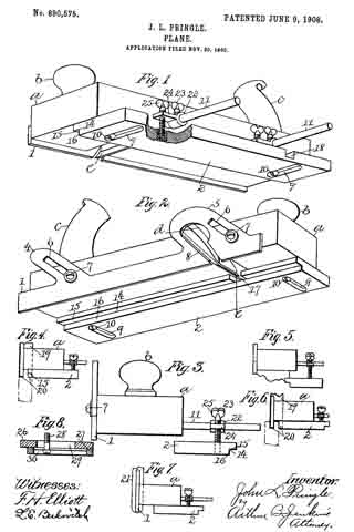
Figure 1 is a perspective view illustrating the bottom and one side of a plane embodying my invention. Fig. 2 is a like view looking from the opposite side of the plane. Fig. 3 is an end view showing the bottom gage-sole used as a side gage. Fig. 4 is what may be termed an illustrative view showing the application of my improvement in cutting a tongue on the edge of a board. Fig. 5 is a like view showing the improvement adapted to the formation of a molding. Fig. 6 is a like view showing the improved tool adapted to cut a groove in the edge of a board. Fig. 7 is a like view showing the improved tool as applied to cutting a concaved surface. Fig. 8 is a view illustrating a modified form of the adjustable gage-sole.

In the accompanying drawings the letter a denotes the body or stock of tlie plane, b a knob or handheld at the forward end, and c a handle located at or near the rear end and on the upper surface of the body part in the usual manner. The body part may be constructed of wood or of any other desired material common to tools of this class. The body part is also provided with a depthwise opening d in which the blade or bit e is located. All of these parts may be of any ordinary and well-known construction.

In carrying out my invention I provide a vertically adjustable secondary sole 1 secured preferably to the side part of the body of the plane, and a laterally adjustable gage-sole 2 which is located underneath the body. The sole 1 includes a plate extendin lengthwise of the body part of the plane, this plate being of proper width and thickness for the purposes in hand, and as shown herein, and as ears 4–5 projecting from the upper edge thereof. These ears are provided with slots 6 through which adjusting studs or screws 7 extend for the purpose of holding the plate in any position of vertical adjustment. An opening 8 is also formed through the ear 5 through which cutting tools or blades of various form may project.

The gage-sole 2 has slots 9 extending laterally thereof formed therein, and studs or screws 10 projecting through these slots into the body of the plane serve as a means of securing the shoe in any position of lateral adjustment. The heads of the screws 10 are located well within the slots, the latter being shouldered to receive the head of the screw. These slots 9 are located at equal distances from the ends of the sole so that the latter may be reversed end for end for certain purposes to be hereinafter described.

It will be seen from the above description and the accompanying illustration that by removing the soles 1 and 2 the plane may be used for all the purposes of a smoothing plane or other surfaces. By placing the secondary sole 1 in position and providing the proper cutting blade the plane may serve the purpose of a plow. By placing the gage-sole 2 and adjusting it in proper position laterally on the bottom of the body part with a proper shaped blade in position, the plane may be used to out moldings of different form. By properly adjusting the soles 1 and 2 with respect to each other and using a blade of proper form articles may be formed of curved shape or round.

The gage-sole 2 is provided on one edge with a recess 14 the walls of which are located preferably at right-angles to each other. When this groove is employed what may be termed the horizontally arranged wall 15 will serve as the bottom proper or sole of the plane, in connection, of course, with the secondary sole 1, and the side or vertically arranged wall 16 will form a gage.

The gage-sole 2 is provided with blade recesses 17 and 18. These recesses are formed to receive one side of the blade of a bit when the tool is used for certain purposes. As shown in Fig. 2, the recess 17 covers one side of the cutting edge of a comparatively wide bit, so that the pidane with such bit may be used as a fillister plane.

By adjusting the gage-sole 2 vertically and laterally, as shown in Fig. 5 of the drawings, and also by adjusting the second ary sole 1 it will be seen that the plane is readily adapted for cutting various forms of moldings, the blade 18 being, of course, properly adjusted.

By adjusting the parts as shown in Fig. 4 the device is adapted for cutting a tongue on the edge of a board, the bit 19 having one of the prongs lying within the opening 8 in the vertical guide, and the other prong extending through the shoulder 15, the edges of these being shown projecting as at 20 in Fig. 4. By reversing the gage-sole 2 and moving it to the position shown in Fig. 6 the device may be used for cutting a groove on the edge of a board, the same knife as shown in Fig. 4 being employed, and that point located within the opening in the secondary sole 1 cutting the groove and the other point being located within the recess 18 in the sole 2, as shown in dotted outline in Fig. 6.

If a circular or curved recess is to be reduced then a blade 21, as shown in Fig. 7 of the drawings, may be used, having its cutting edge of proper form, the extreme curved edge of the blade being located just in advance of the sole 1, and the sole 2 being emlployed as a guide.

In order to adapt the sole 2 for vertical adjustment adjusting supports are mounted on the arms 11, these consisting of a sleeve 22 having set screws 23 with wings 24 bearing adjusting screws 25 which engage threaded sockets in the surface of the gage-sole 2. When the gage-sole 2 is used with the recess 14 facing the secondary sole 1, as shown in Figs. 1, 2, 4, and 5 of the drawings, the screws 10 may be turned out of the stock a or may be removed entirely. It is also obvious that when the gage-sole 2 is used as shown in Figs. 1 and 2, the adjusting screws 25 are not absolutely essential, a though they form a means of support for the projecting edge of the sole.

While the secondary sole 1 has been shown herein as adjustable it is obvious that advantageous results would follow its use in a plane in which it was rigidly secured to the stock without any means of adjustment, but by providing the adjustment I secure all of the advantages present in the late as used in either of the ways mentioned.

In the form of adjustable sole shown in Figs. 1 and 2 the gage-sole is reversed end for end when it is desired to employ the sole as a gage. In Fig. 8 I have adapted this form of the invention so that the sole need not be so reversed when it is to be employed as a gage. In this form of the invention I construct the gage-sole in two parts, a main section 26 and an adjustable section 27. The main section is rovided with a groove 29, and the adjustable section with a shouldered groove 30, a screw 28 to take the place of the screws 10 hereinbefore described for holding the parts in engagement and for holding the sole as a whole in place on the sole or bottom of the plane. It will be seen from this construction that with the parts adjusted as shown in Fig. 8 the device is applicable for the same use as shown in Figs. 1 and 2. By loosening the screw and moving the adjustable section 27 so that the edges are flush, then the sole is adapted for a gage, as illustrated in Fig. 3. It will be noted that the parts 1 and 2 act as soles for the plane, that is, they support the plane in a direction depthwise thereof, the secondary sole 1 supporting the plane when grooves, tongues and the like are being cut, and the gage-sole in connection with the secondary sole supporting the plane as when moldings, and rabbets are cut. It will be noted that when either of the soles 1 and 2 are employed the sole proper of the plane is not in use, the latter mainly being employed when the plane is used as an ordinary surface plane.

I claim:

1. A stock having a bit opening and adapted for use as a surface plane, a secondary sole secured to the side surface of said stock and adjustable depthwise to project below the main sole thereof, and a gage-sole underlying said main sole and adjustable laterally thereof, both of said secondary and gage-soles having openings for the bit and adapted to cooperate therewith in the cutting operation.

2. A stock having a bit opening and adapted for use as a surface plane, a secondary sole secured to the side surface of said stock and adjustable depthwise to project below the sole thereof, a age-sole underlying the main sole and lateragy adjustable thereof, and means for securing the latter sole directly to the under surface of the stock, both of said secondary and gage-soles having openings for a bit to cooperate therewith in the cutting operation.

3. A stock having a bit opening adapted for use as a surface plane, a secondar sole secured to the side surface of the stock and adjustable depthwise to project below the main sole thereof, a reversible gage-sole underlying the said main sole, means for securing said sole in position, both of said secondary and gage-soles having bit openings to cooperate with the bit in the cutting operation.

4. A stock having a bit opening and adapted for use as a surface plane, a secondary sole secured to the side surface of the stock and adjustable depthwise to project below the main sole thereof, a reversible gage-sole underderlying said main sole and adjustable laterally thereof, means for securing said gage-sole directly to the bottom of the stock, both of said secondary and gage-soles having openings for a bit to cooperate therewith in the cutting operation.

5. A stock having a bit opening and adapted for use as a surface plane, a secondary sole secured to the side surface of the stock and adjustable depthwise thereof to project below its main sole, a gage-sole underlying the stock and adjustable vertically and laterally thereof, and means for adjustably securing said gage-sole directly to the under surface of the stock, both of said secondary and main soles having bit openings to cooperate therewith in the cutting operation.

6. A stock having a bit opening, and adapted for use as a surface plane, a secondary sole secured to the side surface thereof and adjustable depthwise to project below its main sole, a gage-sole underlying the stock and vertically and laterally adjustable thereof, means for adjustably securing said sole directly to the under surface of the stock and including slots for the reception of screws and recesses for the reception of the heads thereof, screws for securing said soles, each of said secondary and main soles having openings for a bit to cooperate therewith in the cutting operation.

7. A stock having a bit opening and adapted for use as a surface plane, a secondary sole secured directly to the side surface and adjustable deipthvvise to project below the main sole thereo, a reversible gage-sole underlying the stock and adjustable vertically and laterally thereof, and means for securing said sole directly to the main sole of the stock, both of said secondary and main soles having openings for the bit to cooperate therewith in the cutting operation.

8. A stock having a bit opening and adapted for use as a surface plane, a secondary sole secured to the side surface of the stock and adjustable depthwise to project below the main sole thereof, a gage-sole underlying the stock and reversible thereon and vertically and laterally adjustable thereof , slots in said sole for the reception of screws and recesses for the heads thereof, and screws for securing said sole directly to said main sole, both of said secondary and main soles having openings for a bit to cooperate therewith in the cutting operation.

JOHN L. PRINGLE.

Witnesses:
ARTHUR B. JENKINS,
LENA E. BERKOVITCH.

No. 280,175 – Match-Plane (Philip Hickey) (1883)

[paiddownloads id=”337″]280175


UNITED STATES PATENT OFFICE.

_________________

PHILIP HICKEY, OF BOSTON, MASSACHUSETTS.

MATCH-PLANE.

_________________

SPECIFICATION forming part of Letters Patent No. 280,175, dated June 26, 1883.
Application filed April 28, 1883. (No model.)

_________________

To all whom it may concern:

Be it known that I, PHILIP HICKEY, of Boston, in the county of Suffolk and State of Massachusetts, have invented certain new and useful Improvements in Match-Planes, of which the following is a full, clear, and exact description.

The main object of this invention is to adapt a match-plane for it to be used for the making both of a tongue and a groove fitting each other without changing the plane or bit iron, and also another object is to adapt a match-plane, by simply substituting one plane or bit iron for another, for the making of tongues and grooves of varying widths, but as to the grooves and tongues made by either of the irons so substituted, secure the perfect fitting or jointing.

In this improved match-plane the bit or plane iron is of a forked shape at its cutting-edge — that is, it has two separate cutting edges or blades, between which is an opening of a width which determines the width of tongue cut by the plane and the cutting-blade. The outer of the two, relative to the working-face of the gage upon the bottom or sole of the plane, is of a width equal to the width of said opening between the cutting-blades, or, in other words, of the width of the tongue out by the plane, and said gage is attached to the bottom or sole of the plane-stock, so as to be adjusted transversely thereon, and set either for the cutting of a tongue with both of the blades, or of a groove with said outer blade only of the two blades. The other blade being covered by said gage is thus put out of operative position, and all in a manner to secure a perfect fitting of said tongues and grooves so cut when joined together, and otherwise, substantially as hereinafter described.

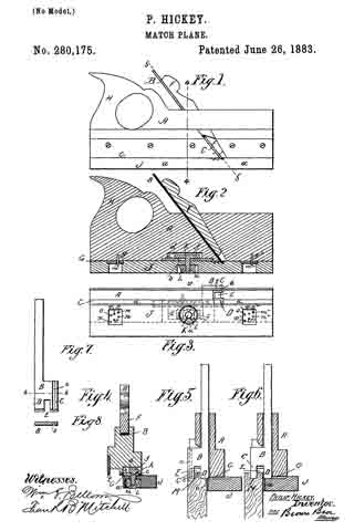
In the accompanying plate of drawings the present improved plane is illustrated, Figure 1 being a side view; Fig. 2, a longitudinal vertical section through the plane and gage; Fig. 3, a face view of the bottom or sole with gage adjusted and set for the cutting of a tongue. Fig. 4 is a cross vertical section on line 4 4, Fig. 1; Fig. 5, a cross vertical section on line 5 5, Fig. 1, which is along the upper face of the plane or bit iron; Fig. 6, a similar view to Fig. 5, but with the gage adjusted and set for the cutting of a groove instead of a tongue, as in Fig. 5, and in the preceding figures. Fig. 7 is a face view of the plane or bit iron detached, and Fig. 8 a cross-section on line 8 8, Fig. 7.

In the drawings, A represents the stock of a match-plane; B, the plane or bit iron, made of a fork shape, or, in other words, with two cutting blades or edges, C D, leaving an opening, E, between them; F, the wedge for fastening the plane-iron B in position; G, the bottom or sole of the stock A; H, the toat or handle, and J the gage running along the length of the sole or bottom G to the stock, and otherwise, except as hereinafter particularly described, the same as ordinary in match-planes for cutting a tongue along the edge of a board, the width of which is determined by the width of the opening E between the two cutting-blades C D.

The cutting-blade C, which is the outer one of the two blades C D relating to the working-face a of the gage J, in its position for the cutting either of a tongue or groove, as the case may be, (see Figs. 5 and 6,) is of a width equal to the width of the opening E between the two cutting-blades, and in the use of this plane, as will hereinafter appear, it of itself and alone cuts the groove.

The gage J is attachable to and detachable from the sole or bottom G of the plane-stock A, and is secured in place by a headed screw-bolt, K, and screw-nut L.

The bolt K passes loosely through the thickness of the gage J and a slot, b, of a plate, c, attached to and covering a recess, d, in the bottom. or sole G of the plane, and the bolt-head f is in said recess, and the recess d, together with said slot b, are in a line at right angles to the working-face a of the gage J, and of a length to allow thc gage to be laterally adjusted upon the sole G of the plane for the purposes of this invention.

g g2 are two projecting pins, one near each end of the sole of the plane, and in a parallel line with the working-face a of the gage.

m m2 and n n2 are four holes to receive the pins g g2. These holes are situated two at each end of the face of the gage which is next to the sole of the plane, and the two at each end are in a line at right angles to the working-face of the gage, and at a distance from each other axially equal to the width of the tongue M which the plane-iron B is adapted to cut, and they are otherwise so arranged that the gage can be set upon the pins g g2 of the plane either by the two holes m and m2 or by the holes n and n2, in each instance one at each end of the gage, and when so set in either case have the working-face a of the gage in proper position for working against the face of the board to be tongued or grooved along its edge.

To set the gage J by either of its holes m and m2 or n n2 upon the pins g g2 of the plane, it is only necessary to first release the fastening nut and bolt K L, and then, having placed it by its holes desired upon the pins, to tighten up said bolt and nut, thus firmly fixing the gage in place. With the gage J adjusted and set as described, by its holes m and m upon the pins g g2 of the plane, the plane is adjusted for the cutting of a tongue, M, as shown in Fig. 5, and with the gage adjusted and set as described, by its holes n and n2 upon said pins, the plane is adjusted for the cutting of a groove, N, as shown in Fig. 6. In the first instance said setting of the gage exposes the two blades C D of the plane-iron for cutting the edge of the board, and in the second instance said setting of the gage leaves only one cutting-blade, and that the outer, C, of the two blades relative to the working-face a of the gage, and covers up the other blade, D, or, in other words, places it out of operative position, and as the distance between the holes m m2 and n n2 of each set of holes equals the width of tongue which the plane-iron B can cut, and the width of the outer cutting-blade, C, equals also the width of said tongue, it is obvious that by these two adjustments of the gage, together with a plane-iron having an outer cutting-blade, C, and an opening between it and the other cutting-blade, D, of equal width, the same plane, using only one plane-iron, is capable of adjustment for the cutting either of a tongue or of a groove, which tongue and groove, when cut, will fit each other and secure a perfect match, of course provided boards are used of the proper thickness.

To render the gage adjustable with the substitution of plane-irons for the plane-iron B, particularly shown in the drawings — that is, plane-irons having a different width of opening E between their two cutting-blades C D, and their outer cutting-blade equal to the width of said opening — and thus to render one and the same plane capable of cutting grooves and tongues of different widths, but in each instance, with the use of any iron, secure a tongue and a groove of the same width when the gage is properly adjusted therefor, the gage is provided with a series of holes — such as o o2 and p p2 — arranged and located and otherwise in every respect similar to the holes m m2 n n2, before described, varying only in this respect, (if it may be termed a variation,) that the transverse distance of each of said sets of holes corresponds to the width of groove and tongue which the plane is to and can cut when another plane-iron of different width of opening E between its cutting-blades and a width of outer cutting-blade corresponding thereto is substituted for the plane-iron B, particularly shown in the drawings, and the gage is properly placed with its set of holes o o2 p p2 belonging to the so-substituted plane-iron.

As the pins of the plane and the setting-holes m m2 n n2 of the gage are fixed points, in order to insure the proper locating of different plane-irons in the plane relative thereto, a groove, s, is made in the back of the outer cutting-blade, C, of each plane-iron, (see Figs. 7 and 8,) to fit over the edge t of the plane opposite to that of the gage, and, as the pins g g2 of the plane and the setting-holes m, m2, n, and n2 of the gage are located in the drawings, the groove is along the center line of the width of said cutting-blade; but it is plain that, were either the setting-holes or the pins located differently relative to the position of the plane-iron in the plane, the position of said groove would be necessarily changed. The pins g g2 may be on the gage and the holes m m2 n n2 in the plane, and, as is obvious, these means absolutely insure the adjustment herein described of the gage to the plane-iron used. It is plain, however, that other means might be substituted for said pins and holes, and yet insure absolutely said adjustments of the gage.

The screw-nut of the fastening device for the gage is preferably countersunk in a recess, u, of the gage, and in lieu of the fastening device for the gage particularly described and shown others may be substituted.

Having thus described my invention, what I claim, and desire to secure by Letters Patent, is —

1. In a match-plane, a plane-iron, B, having cutting-blades C D, with an opening, E, between them, and the outer blade of the width of the tongue to be cut and of said opening, in combination with a gage, J, adapted for arbitrary and rigid adjustment, substantially as and for the purpose described.

2. In a match-plane, a plane-iron, B, having cutting-blades C D, with an opening, E, between them, and the outer blade, C, of the width of the tongue to be cut and of said opening, in combination with a gage, J, adapted by pins g g2 and holes m m2 n n2, together with a suitable fastening device, to be adjusted, substantially as described, for the purposes specified.

3. In a match-plane, a plane-iron, B, having cutting-blades C D, with an opening, E, between them, and an outer blade, C, of the width of the tongue to be cut and of said opening, and adapted to interlock; with the flange or rib t of the plane, in combination with an adjustable gage, substantially as and for the purpose described.

4. In a match-plane, a plane-iron, B, having cutting-blades C D, with an opening, E, between them, and the outer blade, C, of the width of the tongue to be cut and of said opening, in combination with a gage adapted by sets of pins g g2 and holes m, m2, n, and n2, together with a suitable fastening device, to be adjusted for different plane-irons of the above-said construction, substantially as and for the purpose described.

In testimony whereof I have hereunto set my hand in the presence of two subscribing witnesses.

PHILIP HICKEY.

Witnesses:
EDWIN W. BROWN,
WM. S. BELLOWS.

No. 230,088 – Bench-Plane (William T. Wainwright) (1880)

[paiddownloads id=”309″]230088


UNITED STATES PATENT OFFICE.

_________________

WILLIAM T. WAINWRIGHT, OF DRY SAWMILL, PENNSYLVANIA.

BENCH-PLANE.

_________________

SPECIFICATION forming part of Letters Patent No. 230,088, dated July 13, 1880.
Application filed April 28, 1880. (No model.)

_________________

To all whom it may concern:

Be it known that I, WILLIAM T. WAINWRIGHT, of Dry Sawmill, in the county of Elk and State of Pennsylvania, have invented a new and useful Improvement in Planes, of which the following is a specification.

My invention consists in certain novel details of construction and arrangement of parts, whereby the same tool may be used for square-jointing, for beveling, and for rabbeting, as hereinafter particularly described.

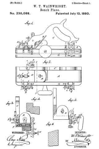
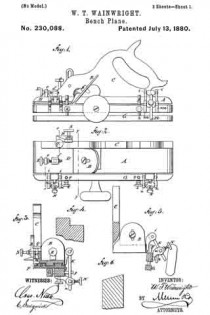
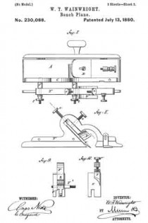
In the accompanying drawings, Figure 1 is a side view of a plane embodying my improvements. Fig. 2 is a top view of the same. Fig. 3 is a transverse vertical section taken in the line x x of Fig. 2. Fig. 5 is a transverse vertical section taken in the line y y of Fig. 2. Figs. 4. and 6 are views hereinafter referred to. Figs. 7, 8, 9, and 10 are views of grooving and tonguing attachments as applied to my plane, hereinafter referred to.

Similar letters of reference indicate corresponding parts.

The plane A, bit B, and handle C may be of the usual or any suitable description.

To the front end of the plane is attached (see Fig. 3) a block, D, which slides on tongue-and-groove dovetail ways arranged longitudinally of the plane, and may be adjusted nearer to or farther from the bit B, in order to regulate the size of the throat, by means of a thumb-screw, E, working through a standard, e, attached to the block D, and engaging with an internally-threaded standard, f attached to the plane A, and passing through a slot in the block.

To the left-hand side of the plane is hinged a bar, G, composed of two pieces connected by pins g. One end of each pin is fast to one of the pieces, and the remainder of its length is arranged to slide in a hole in the other piece transversely to a set-screw, lt, the point of which bears against the pin. By this means the bar may be widened or narrowed, to accommodate work of different widths.

To the plane A are attached two pairs of perforated lugs, i i, i i, which form bearings for lateral gudgeons extending from one end of each of two pins, K K, the remaining portion of each of which slides in a globe, l, provided with lateral gudgeons having their bearings in perforated lugs m, arranged in pairs and attached to the bar G, and each provided with a thumb-screw, N, the point of which bears against the pin K. By this means the bar G may be adjusted at an angle with relation to the plane, as shown in Fig. 5, so as to plane a bevel, as shown in Fig. 6 of the drawings, or may be adusted at any other suitable angle; and when not in use it may be folded under the plane, as shown in Fig. 3.

On the right-hand side of the plane (see Fig. 3) is a recess, in which works a cutting-blade, P, regulated by a thumb-screw, Q, working in the handle C. On the outer side of the handle is a slotted gage, B, provided with a thumb-screw, S. By means of this cutting-blade P and the plane-bit B a rabbet (such as is shown in Fig. 4) may be cut, and the depth of cut is regulated by the gage R and screw S.

Figs. 7, 8, 9, and 10 represent an attachment for making tongues and grooves. It consists of a bar, T, attached to the plane A by screw-bolts T2, provided with heads t.

The bar T carries a tonguing-bit, U, which may be changed for a grooving-bit. Both of said bits are held in place by a thumb-screw, u, which passes through a slot in the shank of a cutting-bit, V, provided with a thumb-screw, v, for adjusting it.

The bit V is intended to make a cut parallel with the line of travel of the tonguing or grooving bit and co-operate with said bit in removing the shavings. When this attachment is not in use it may be removed and laid aside by unscrewing the bolts T2.

Having thus described my invention, I claim as new and desire to secure by Letters Patent —

1. The combination, with the plane A, of the hinged bar G, lugs i and m, pins K, globes l, and screws N, fbr adjusting the plane for beveling, as herein shown and described.

2. The combination, with the plane A, of the rabbet-cutting blade P, screw Q, gage R, and screw S, as herein shown and described.

WM. TYLER WAINWRIGHT.

Witnesses:
GEORGE A. JOHNSON,
JOHN WAINWRIGHT.

No. 148,649 – Improvement In Metallic Bench-Planes (John A. Baines) (1874)

[paiddownloads id=”227″]148649


UNITED STATES PATENT OFFICE.

_________________

JOHN A. BAINES, OF NEW YORK, N. Y.

IMPROVEMENT IN METALLIC BENCH-PLANES.

_________________

Specification forming part of Letters Patent No. 148,649, dated March 17, 1874; application filed February 9, 1874.

_________________

To all whom it may concern:

Be it known that I, JOHN A. BAINES, of New York city, in the county of New York and in the State of New York, have invented certain new and useful Improvements in Metallic Bench-Planes; and do hereby declare that the following is a full, clear, and exact description thereof, reference being had to the accompanying drawings making a part of this specification, in which —

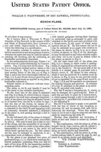
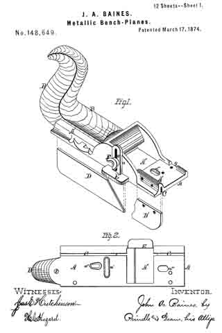
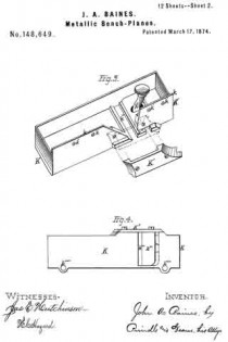
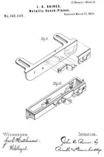
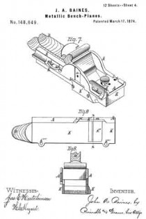
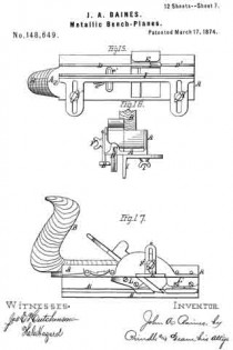
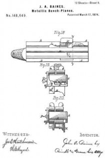
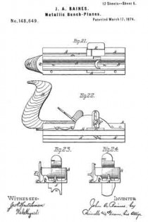
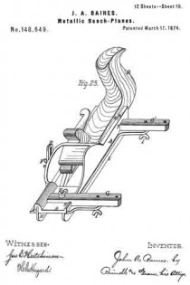
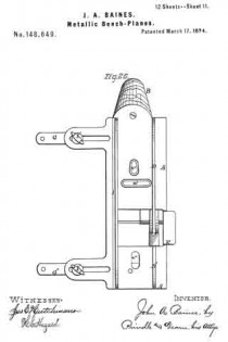
Figure 1 is a perspective view of the main frame, side gage, and sole or base plates of my plane. Fig. 2 is a plan view of the lower side of said frame. Fig. 3 is a perspective view of the detachable block or frame used for forming the smoothing and filletster planes. Fig. 4 is a plan view of the lower side of the same. Fig. 5 is a perspective view of the bottom gage. Fig. 6 is a like view of the detachable block employed for forming the sash-plane. Fig. 7 is a perspective view of the smoothing-plane complete. Fig. 8 is a plan view of the lower side of the same. Fig. 9 is a vertical section upon line x x of Fig. 8. Fig. 10 is a side elevation of the filletster-plane. Fig. 11 is a plan view of the lower side of the same. Fig. 12 is a plan view of the lower side of the tonguing-plane. Figs. 13 and 14 are, respectively, side and front elevations of the same. Fig. 15 is a plan view of the lower side of the grooving-plane. Figs. 16 and 17 are, respectively, a front and a side elevation of said plane. Fig. 18 is a plan view of the lower side of the sash-plane. Fig. 19 is a front elevation of the same. Fig. 20 is a section of said plane on line z z of Fig. 18, the cutting-tools being arranged for forming the meeting rail. Fig. 21 is a plan view of the lower side of a bead or round plane. Figs. 22 and 23 are, respectively, a side and a front elevation of the same. Fig. 24. is a front elevation of a hollow plane. Fig. 25 is a perspective view of a plow-plane. Fig. 26 is a plan view of the lower side of the same. Fig. 27 is a like view of a plane for forming center-beads. Fig. 23 is a front elevation of the same; and Fig. 29 is a side view of the cutting-irons employed, showing the shape of the cutting-edge of the same.

Letters of like name and kind refer to like parts in each of the figures.

The design of my invention is to lessen the cost and reduce the bulk of planes for producing irregular work; and to this end it consists in the construction and combination of the frame and various attachments employed for forming the different styles of plane, substantially as and for the purpose hereinafter specified.

In the annexed drawings, A represents the main frame of my tool, which has a plain lower surface, and at its upper side has such conformation as to enable it to receive the usual form of cutting-irons with the fastening-wedge, to permit the upward passage of shavings, and to provide for the attachment of a handle, B. Within the lower side, and near one edge of the frame A, is formed a narrow groove, C, which extends vertically upward within an enlargement or rib, A’, provided for the purpose, has a line parallel to the side of said frame, and receives two plates, D and D’, (shown in Fig. 1,) that form the base or sole. Two or more removable pins, d and d, pass horizontally and laterally inward through the side of said frame A, and through each of said plates D and D’, and locks the latter securely in position, when desired. Upon the inner side of the name A is formed a vertical groove, a, that receives the standard e of an adjustable gage, E, which gage is secured to or upon said frame, and held in vertical position by means of a screw, F, that passes into a threaded opening in the latter through a vertical slot in said standard.

Within the upper side of the frame A, near its ends, are formed two transverse grooves, g and g, that receive the ends of two corresponding bars, G and G’, which bars, when in position, are fastened by means of a screw, H, as shown in the front bar, or a pin, H’, as seen in the rear bar, said screw or pin being passed vertically downward through said bars into said frame. From the frame A the bars G and G’ extend laterally outward, and have their lower sides upon a line with the lower face of the former, in which position they form an extension of said face, and permit of the attachment of an angle-plate, I, (shown in Fig. 5,) which plate, being adjustable laterally toward or from the cutting-irons, forms a gage for several forms of plane. Within the lower side of the frame A, at or near its longitudinal center, is formed a transverse slot, a’; in rear of the same is provided a longitudinal slot, a”; while in front of the throat A” is a second longitudinal slot, a”’, the object of which is to enable the attachment of various parts required for forming several of the planes, said parts being described in connection with each plane of which it forms a part.

For use as a smoothing-plane, a hollow block, K, having the general form shown in Fig. 3, is placed upon the lower side of the main frame, and secured in posiuon by means of its inner side k, which extends upward into the groove C, and is provided with suitable openings k’ for the passage of the pins d and d.

The bolt k” of an adjustable throat-piece, k”’, projects upward through slots in said block and main frame and furnishes an additional means for securing said parts together.

The block K is provided with a throat, k””, which coincides with the throat of the main frame, and enables a cutting-iron, of usual form to be inserted and secured in place by means of the ordinary wedge.

To construct a filletster, the inner end of the throat k”” of the block K is uncovered by the removal of a covering plate or cap, K’, and the gage I attached to the lower face and outer side of said block, suitable threaded openings k””’ being provided within said block, for the reception of the binding-screws I’ of said gage.

The gage E is also placed in position and adjusted to depth, and, in connection with said gage I, enables the dimensions of the fillet or rabbet to be determined with certainty.

For use as a tonguing (matching) plane, the plates D and D’ are placed in position, the gage I attached to the lower face of the frame A, and upon the face of said gage is attached two blocks, L and L’, which have the form shown in Fig. 5, and perform the double office of a support for the heel of the inner half of the cutting-iron, and a gage for the depth of its cut. The gage E is also em-
ployed, its office being to insure the correct depth of cut for the outer half of said cutting-iron.

For a grooving-plane, the blocks L and L’ are removed, the gage I is moved inward to the position required by the thickness of the board, and a single cutting-tool inserted in place of the double one before used. The gage E is now reversed, so as to cause its bearing-face to extend inward nearly to the cutting-iron, the arrangement of parts being as shown in Figs. 15 and 16.

For use as a sash-plane, the plates D and D’ and the gages E and I are removed, and a block, M, having the form shown in Figs. 6 and 20, secured upon the lower side of the frame A by means of a screw, m, which extends upward through the longitudinal slot a” in said frame, and a second screw, m’, that passes downward through the transverse slot a”’ near the front end of said frame, and has its threaded end contained within a corresponding opening provided in said block. The blocks L and L’ are now attached to the inner face of the block M, where they serve as supports and gages for the cutting-iron that forms within the sash-rail the rabbet for containing glass, while the cutter for forming the molding upon said sash-rail is placed within a suitable throat formed in and through the molded face of said block M.

For use in forming the meeting rail, the gage-blocks L and L’ are removed, and the cutter shown in Fig. 20 inserted in place of that before employed for forming the glass rabbet.

For use as a beading or rounding plane, the block M is removed and a block, N, having the transverse shape shown in Fig. 23, is secured in its place upon the frame A, the size and shape of the groove it within the lower face of said blocks N and the corresponding features of the cutting-iron being varied to suit the especial purpose for which the tool is required.

To form a hollow plane, the shape of the lower face of the block N and of the edge of the cutting-iron are reversed, as shown in Fig. 24.

For use as a plow, the plates D and D’ are placed within the groove C, and the adjustable gage I secured upon the lower face of the frame A, or upon the extension–bars G and G’, after which the usual form of cutting-iron is inserted within the space between said plates, its heel resting upon the forward end of the rear plate D.

To form a center-bead plane, the extension-bars G and G’ and gage I are employed as before, the plates D and D’ are removed, and a hollow block, O, having the transverse form shown in Fig. 28, secured upon the lower face of the frame A. A cutting-iron having its lower or cutting end formed upon a line which corresponds to the grooved face of said block is placed in position within the throat o of the same, after which the plane is used in the ordinary manner.

As seen in Fig. 29, the lower end and forward side of such plane-irons as usually require caps are beveled off at an angle of about forty-five degrees with said side, so as to render more obtuse the angle of the cutting-edge, and enable any kind of wood to be cut smoothly and with ease without the use of a cap, by which means a saving is effected in the cost of said cutting-irons, and in the time and labor required in manipulating the planes.

The device thus constructed combines, in a simple and compact form, a number of tools which are usually separate, and enables them to be furnished at a comparatively small cost.

Having thus fully set forth the nature and merits of my invention, what I claim as new is —

The hereinbefore-described plane, constructed in the manner and for the purpose substantially as specified.

In testimony that I claim the foregoing, I have hereunto set my hand this 6th day of February, 1874.

JOHN A. BAINES.

Witnesses:
JOHN R. YOUNG,
JAS. E. HUTCHINSON.

No. 149,026 – Improvement In Grooving And Tonguing Planes (Richard Brown) (1874)

[paiddownloads id=”228″]149026


UNITED STATES PATENT OFFICE.

_________________

RICHARD BROWN, OF NEWARK, NEW JERSEY.

IMPROVEMENT IN GROOVING AND TONGUlNG PLANES.

_________________

Specification forming part of Letters Patent No. 149,026, dated March 31, 1874; application filed December 27, 1873.

_________________

To all whom it may concern:

Be it known that I, RICHARD BROWN, of the city of Newark, in the county of Essex and State of New Jersey, have invented certain Improvements in Grooving and Tonguing Planes, of which the following is a specification:

My invention relates to a match-plane adapted for cutting both tongues and grooves. The invention consists in the combination, with such plane, of a central guide, arranged between the two soles and stocks of the plane, and made capable of lateral adjustment in either direction, so as to adapt the plane to cut the tongue and groove in the edge of the lumber at a greater or less distance from the plane of one of the sides thereof, as may be required.

In the accompanying drawings, Figure 1 is a side elevation of my improved plane. Fig. 2 is an elevation thereof with one-half of the stock removed. Figs. 3, 4, and 5 are cross-sections, respectively, in lines x x, y y, and z z, Fig. 2.

Like letters of reference designate like parts in each of the figures.

A A’ represent the two stocks of the plane; B, the tonguing-iron, and B’ the grooving-iron, arranged in the stocks A A’, respectively, in the ordinary manner. C is the guide or fence, arranged centrally between the lower portions of the stocks A A’. It consists of a straight metallic bar or plate, of equal length with the stocks, having an upper and thinner portion, c, fitting in recesses formed in the adjacent sides of the two stocks, and a lower and wider portion, c’, projecting below the soles of the stocks, and resting against the same by means of rectangular shoulders or offsets, as clearly shown in Figs. 3 and 5.

The two stocks are connected with the guide C, so as to be capable of lateral adjustment, each independent of the other, in the following manner: D D represent two horizontal set-screws, arranged transversely in the stock A, near its ends, and working in threaded holes d in the portion c of the guide C. These set-screws are retained against lengthwise movement in the stock A by their heads turning in contact with the outer face of metallic washers E, secured in the side of the stock A, and a pin, f, passing through each set-screw in contact with the inner surface of said washers, or by equivalent means. D’ D’ represent two similar set-screws for connecting the stock A’ with the guide C. They are arranged in the same horizontal plane with the set-screws D D, but not so as to coincide therewith, as clearly shown in Fig. 2. G is a horizontal screw-bolt, arranged transversely and centrally in the guide C, as shown in Figs. 2 and 5, so that its ends project from either side of the guide into the two stocks A and A’, respectively, which latter are provided with suitable recesses for that purpose. The threaded bolt G is secured in the guide G by a pin or otherwise, to prevent it from turning in its seat. H H’ represent two tubular screws, or countersunk screw-nuts, engaging with the projecting ends of the screw-bolt G, and bearing, with their heads, against the sides of the stocks A and A’, respectively, which are, preferably, provided with countersunk metallic washers i as bearing-surfaces.

In Fig. 3 the two stocks A and A’ are shown in close contact with the central guide C, in which condition of the implement the groove and tongue are cut closer to the guide C, resting against the side of the board which is being operated upon.

In order to increase the distance at which the tongue or groove, or both, are cut from the guide C, the respective tubular screw is first sufficiently loosened, when the set-screws of the stock requiring adjustment are gradually turned, so as to screw out of the guide C, until the required distance is obtained, when the tubular screw is tightened, and the stock thereby firmly secured in this position.

The set-screws D D’ and bolt G are, preferably, arranged in the same horizontal plane, to prevent bending of the set-screws by the tightening of the nuts H H’.

Irons of different widths may be used in the implement, in order to adapt the same to lumber of different thicknesses.

The stocks are adjusted in the opposite direction, in an obvious manner, by the reversal of the above-described operation.

What I claim as my invention is —

The combination and arrangement, with the two stocks A A’, of the central adjustable guide C, set-screws D D’, bolt G, and screw-nut H H’, adapted to operate as and for the purposes set forth.

RICHARD BROWN.

Witnesses:
CHAS. E. HILL,
FREDERICK H. WOOLFALL.

No. 181,357 – Improvement In Tonguing And Grooving Planes (Charles G. Miller) (1876)

[paiddownloads id=”59″]181357


UNITED STATES PATENT OFFICE.

_________________

CHARLES G. MILLER, OF NEW BRITAIN, CONNECTICUT, ASSIGNOR TO STANLEY RULE AND LEVEL COMPANY, OF SAME PLACE.

IMPROVEMENT IN TONGUING AND GROOVING PLANES.

_________________

Specification forming part of Letters Patent No. 181,357, dated August 22, 1876; application filed July 17, 1876.

_________________

To all whom it may concern:

Be it known that I, CHARLES G. MILLER, of New Britain, in the county of Hartford and State of Connecticut, have invented an Improvement in Tonguing and Grooving Planes, of which the following is a specfication:

In Letters Patent No. 165,355, granted July 6, 1875, a plane is shown with two cutters and an intermediate groove for the tongue that is left upon the edge of the piece of wood, and there is a guide that can be turned around or reversed when the plane is to be used for grooving. In this plane there is but one guide for the face of the board, the guide having two sides, one of which comes against the board in planing the tongue, and the other comes against the face of the board in planing the groove after the guide has been swung around for that purpose.

My present improvement consists in the combination, with a tonguing and grooving plane and stationary guide, of a second guide that is movable in a plane parallel to the face of the stationary guide, so that the plane can be used in the ordinary manner for tonguing the edge of the board, the movable guide remaining out of the way while so doing, and upon depressing the movable guide it changes the tool into a grooving-plane, so that only one cutter is used to form the groove.

In the drawing, Figure 1 is a side view of the plane. Fig. 2 is an inverted plan. Fig. 3 is a section at x x, with the movable guide or fence out of use; and Fig. 4 is a section at the line y y, representing the plane as in use for forming a groove.

The stock a, handle b, and knob c, are of any usual or desired size or character. The two cutters e and f are also constructed in the ordinary way and clamped, preferably by levers and thumb-screws. The stationary guide or fence It is upon the plane-stock, and I runs against the face of the board in the ordinary manner when the plane is being used to form a tongue. The cutter e is of the same width as the tongue ; hence to use said cutter in forming a groove it is only necessary to introduce a movable fence or guide at the proper distance from the cutter to enable the work-man to use the plane for grooving the wood for the reception of the tongue.

I accomplish this object by using the movable fence or guide i that moves in a plane parallel with the face of the stationary guide k.

I have shown this guide i as sliding vertically in a narrow channel made through the plane-stock, and the guide i is attached at one side of a headed stud, k’, that passes through the hollow stud l upon the plane-stock.

The portion of the stock that forms the bed for the cutters is slotted or channeled to allow of the movement of this guide ; so, also, is the stud upon which the knob e is placed. When the guide fi is pushed down into position shown in Fig. 4, the plane is adapted to grooving, and when said guide is not needed, it is moved in the plane parallel to the face of the board so as to be out of the way when using the plane for forming the tongue. This guide i might be pivoted at one end and swing in the same plane of motion as aforesaid, in a manner similar to a knife-blade.

I claim as my invention —

The combination, with a tonguing-plane, having stock a, cutters e and f, and guide k, of the second guide or fence i, moving in a plane parallel to the face of the stationary guide, substantially as set forth.

Signed by me this 7th day of July, A. D.
1876.

C. G. MILLER.

Witnesses:
JULIUS H. PEASE,
ISAAC PORTER.

No. 165,355 – Improvement In Tonguing And Grooving Planes (Charles G. Miller) (1875)

[paiddownloads id=”57″]165355


UNITED STATES PATENT OFFICE.

_________________

CHARLES G. MILLER, OF NEW BRITAIN, CONNECTICUT, ASSIGNOR TO THE STANLEY RULE AND LEVEL COMPANY, OF SAME PLACE.

IMPROVEMENT IN TONGUING AND GROOVING PLANES.

_________________

Specification forming part of Letters Patent No. 165,355, dated July 6, 1875; application filed April 9, 1875.

_________________

To all whom it may concern:

Be it known that I, CHARLES G. MILLER, of New Britain, in the county of Hartford and State of Connecticut, have invented an Improvement in Tonguing and Grooving Planes, of which the following is a description and specification, reference being had to the accompanying drawings, where —

Figure 1 is a side view of a plane embodying my invention, the view showing that side of the tool upon which the shifting guide, hereinafter described, is hung. The tool is adjusted as a tonguing-plane. The view from this side is, however, precisely the same when the tool is adjusted as a grooving-plane. Fig. 2 is a front-end view of the tool adjusted as a tonguing-plane, showing the pivot, on which the shifting guide is hung, in central vertical section. Fig. 3 is a front-end view of the tool adjusted as a grooving-plane.

This invention is a device which is, at pleasure, a plane for tonguing the edges of boards, or a plane for grooving the edges cf boards to receive such tongues. It is a tool for use in making what is known to carpenters as “matched stuff,” and combines in itself both a tonguing and a grooving tool.

The invention consists in a shifting guide, which can be adjusted so as to leave both the knives or chisels uncovered, making a tonguing-plane of the tool; or it can be adjusted to cover one of the chisels or knives, making a grooving-plane.

The letter a denotes the metallic stock or body of the tool; b, the handle, and c the throat, down which runs what carpenters call the “iron” d, forked at its lower end into the two chisels d1 d2, which do the cutting. e denotes the wedge which holds the iron in place. The letter f denotes the shifting guide, eccentrically attached to the shaft i, hung and rotating in the socket g, attached to the stock a. The pin i1 runs into the top of the shaft or trunnion i, and forms, practically, a part thereof. The spring m, bearing between the shoulders g1 i2, presses the guide f constantly upward. In either adjustment, for tonguing or for grooving, the guide f is held to position by the pins n, (shown in dotted lines,) which project downward from the fingers o, which project side-wise from the stock a, three teats entering corresponding holes in the top of the guide f.

When the operator desires to shift the adjustment of the guide f, he presses downward upon the top of the pin i1 till the guide clears the pins n, when it can be readily rotated upon its pivot in the socket g from one adjustment to the other.

In place of the vertical movement allowed, by this construction and arrangement, to the guide f, I contemplate depriving the guide of this vertical play, and in place thereof make one of the pins n, or both of them, a spring-catch.

When the guide f is adjusted as shown in Fig. 2, both the chisels d1 d2 are left uncovered for work, and the tool forms a tonguing-plane. When the guide f is adjusted as shown in Fig. 3, one of the chisels is covered, and the tool forms a grooving-plane; and these differences of adjustment are due to the fact that the guide f is hung eccentrically upon its pivot.

I claim as my invention —

ln combination with the body or stock a and the chisels d1 d2, the guide f, having adjustments to cover and uncover one of the chisels, substantially as shown and described.

CHARLES G. MILLER.

Witnesses:
FRED. N. STANLEY,
T. A. CONKLIN.

No. 7,938 – Tonguing, Joining And Rabbeting Plane (John A. Fry) (1851)

[paiddownloads id=”6″]7938


UNITED STATES PATENT OFFICE.

_________________

JOHN A. FRY, OF EDINBURG, VIRGINIA.

TOOL FOR TONGUING, JOINING, AND RABBETING.

_________________

Specification of Letters Patent No. 7,938, dated February 18, 1851.

_________________

To all whom it may concern:

Be it known that I, JOHN A. FRY, of Edinburg, county of Shenandoah and State of Virginia, have invented a new and useful Tonguing Plane, and that the following is a full, clear, and exact description thereof, reference being had to the accompanying drawings, which make part of this specification.

The purposes of my invention are to make a tool by the use of which the workman may make tongues of different thicknesses, the same tool being capable of both tonguing and jointing the stuff, and to make the same tool answer the purpose of a rabbetlng plane. The tool might be called a combined jointing-tonguing and rabbeting plane. The advantage of such a tool is that boards or plank of different thicknesses may be tongued with one implement, and yet each may have a tongue out upon it of a thickness adapted to that of the plank. It also enables the workman to diminish the thickness of any tongue if found too thick for the easy putting together of his work. It also saves the trouble of keeping on hand or carrying about three distinct tools instead of one, to perform the three or four operations for which this implement is intended.

My plane is made of two distinct parts or bodies B and B’, Figures 2 and 3; wherein, Fig. 2, is an underside plan and Fig. 3 a top plan. These parts may, by turning back the screws s, s, and screwing up the nut N, N, on the screws S, S, be brought close together, closing up the space m m between the two bodies. When the bodies are thus brought together, the instrument may be used first to joint a board, which it will do if the adjustable guide or gage G, Fig. 2, be brought into the position indicated by the dotted lines, G’. This position it can take by slackening the set screws r r, and slipping the gage piece till the screws occupy the opposite ends of the slots o, o, to those where they are seen in the figure. The plane iron P’ will then serve as a jointing cutter to straighten the edge of the board before commencing the tonguing, the board resting on its edge for both operations.

When a tongue is to be cut, after jointing the board, the slide or gage G is restored to the position seen in the figure (2) or so nearly to it as is required by the thickness of the plank. The two bodies B, B’ may then be either kept close together or they may be separated apart to a distance required by the thickness of the tongue intended to be formed. If they be kept close together the thickness of the tongue will be that of the two half grooves P, P’, but if they be separated by the adjusting screws s s, and fixed by the set screws S S, then will the thickness of the tongue be increased by the distance m of the separation of the two bodies. At whatever distance apart the bodies are set the guide or gage G, sliding along the face of the board determines the breadth of out which shall be made by the cutter P. The cutters P and P’ are both set inclined not only backward from the vertical, but also horizontally from their inner to their outer edges respectively. By this arrangement of the irons the chips or shavings are, when tonguing, thrown outward on the two opposite sides of the plane. The place of discharge is seen at R, in the side elevation of the body B, Fig. 1. The cutters P and P’ are held in place by the oblique wedges W and W’ Figs. 1 and 3.

The cutters have each two edges, one across the end and one on the inner side, whereby the side of the tongue is smoothed at the same time that the wood is cut away on both sides of it to form the jointed shoulders of the tongue. The edges along the sides also serve the purpose of diminishing the thickness of a tongue already made when such diminution becomes necessary.

The handle of the plane is seen at H, Figs. 1 and 3. It is permanently attached to the body B, but its base Q Q (Fig. 3) extends beyond that body and makes a projection which enters a notch M M, in the upper part of the body B’, which notch and projection serve to give a support in a longitudinal direction to the body B’ while the set screws S S confine it laterally to the body B.

When the plane is to be used for rabbeting the body B’ is wholly removed and the set screws S S may be taken out. Then by sliding the guide G on the set screws r r, till the edge w w coincides with or lies over x x, it may be then fastened for the purpose of using the plane to joint a board previous to cutting a rabbet. The plane iron P is driven down till its cross edge comes nearly or quite through the oblique slot V. The edge of the gage G together with the vertical side of the notch P, then serves as the face of the jointer, and the jointing cut is made not by the cross edges but by the side edge of the plane iron P. With the implement having its gage and cutter in the positions just described the board is jointed on its edge while it lies upon its face or flat side, the bottom of the notch or rabbet p resting upon the upper corner of the board and guiding or sustaining the plane.

The board having been jointed, is rabbeted without removing it from the bench. For this purpose, the tool is prepared by sliding the gage G into the position represented by the plain lines in Fig. 2, and the plane iron is set with its cross edge nearly on a level with the line x x, descending only far enough below that level to make its cut.

It is then used to out the rabbet without changing the position of the board, from that in which it lay while being jointed.

From the foregoing description it will be seen that the gage G is brought into use in combination with the notch P and the side edge of the cutter P to form a jointer for a board resting on its face, in a situation to be rabbeted ; that it is combined with the cross edge of the cutter P and with the half groove p to form the rabbeting plane; that when combined with the cutter P’ and the body B’ it forms a jointing cutter to joint a board, set up edgewise in a position to be tongued, and finally that the same gage G in combination with the two bodies B and B’, and the two cutters P and P’, it forms the tonguing plane. The parts of the tonguing plane just specified, together with the parts hereinbefore specified for setting the bodies B and B’ asunder and retaining them in place constitute an adjustable tongue cutter, whereby tongues may be out of different thicknesses to suit the thickness of the stuff or the purpose to which it is to be applied.

Fig. 4 is a cross section through x x Fig. 3, exhibiting the bodies B and B’ the gage G, the fastening screw S and its nut N together with an elevation of the wedges W, W’, plane irons P and P’ and the handle H.

What I claim as my invention and desire to secure by Letters Patent is —

1. So making a jointing, tonguing and rabbeting plane that the jointing and tonguing of a board while resting on its edge, and also the jointing and rabbeting of it while it lies on its flat side may all be performed with one planing tool in the manner substantially as herein described, and for the purposes herein set forth.

2. I also claim making the tonguing hand plane in such a manner as to enable the workman to make therewith tongues of various thicknesses substantially in the manner herein set forth, whereby I prevent the necessity of providing different tools to tongue planks of different thicknesses.

3. I also claim in combination with a divided body or plane stock, the two cutters having each a cross-cutting and a side-cutting edge and the means substantially as herein described for adjusting the distance apart of the two cutters and bodies whereby the plane is made capable of dressing the sides of a tongue to any desired thickness and at the same time to cut the shoulders as herein specified.

4. I also claim in combination with the gage G the use of the body B’ and the cross edge of the cutter P’ to constitute a jointer to straighten the edge of a board preparatory to tonguing it and while resting on its edge in a situation to receive the tonguing.

5. I also claim the gage G in combination with the notch p and the side edge of the cutter P, acting as herein described, as a jointing plane to straighten the edge of a board or plank resting on its flat side, in a position to have a rabbet out in the manner substantially as herein set forth.

JOHN A. FRY.

Witnesses:
GEORGE A. GRUNDSTAFF,
ISAAC RULY.

No. 7,432 – Plane For Tonguing And Grooving Boards (James A. Woodbury) (1850)

[paiddownloads id=”4″]7432


UNITED STATES PATENT OFFICE.

_________________

JAMES A. WOODBURY, OF BOSTON, MASSACHUSETTS.

PLANE FOR TONGUING AND GROOVING BOARDS, &c.

_________________

Specification of Letters Patent No. 7,432, dated June 11, 1850.

_________________

To all whom it may concern:

Be it known that I, JAMES A. WOODBURY, of Boston, in the county of Suffolk and State of Massachusetts, have invented certain new and useful Improvements in Apparatus for Tonguing and Grooving Boards, Planks, &c., and that the following description, taken in connection with the accompanying drawings hereinafter referred to, forms a full and exact specification of the same, wherein I have set forth the nature and principles of my said improvements by which my invention may be distinguished from others of a similar class together with such parts as I claim and desire to have secured to me by Letters Patent.

The figures of the accompanying plate of drawings represent my improvements.

Figure 1 is a side elevation of hand plane arranged with my improvements for cutting, or forming tongues in boards or planks. Fig. 2 is a top view of the same.

Fig. 3 is an isometrical perspective view of a gouge used in said plane, and Fig. 4 is a similar view of a smoothing chisel set behind this gouge in said plane; and Fig. 5 is a plan of the underside of said plane, and Fig. 6 is an end view of the same. Precisely similar views of a hand plane for forming grooves in boards or planks, to those represented in Figs. 1, 2, 3, 4, 5 and 6, are shown respectively in Figs. 7, 8, 9, 10, 11 and 12.

As the implements for forming tongues and grooves are now arranged, there is but a single cutting chisel of the ordinary shape or construction, the edge of which penetrates into the wood, and tears out the shaving from the sides of the groove or tongue, and leaves said sides rough and imperfect. While in cross-grained lumber and wet wood it is almost impossible to form a tongue or groove with the tools now in common use.

The defective operation of the tools heretofore devised, in the particular above noted, has long been sought to be remedied, and by my improvements the difliculties and imperfections above referred to are entirely obviated.

In my improved apparatus I use two cutting tools or chisels. That which first enters the wood is a gouge-cutter with a semi-circular cutting edge, which operates to take out the greater portion of the shaving required to be removed from the groove, or on each side of the tongue. And behind this gouge cutter is set a smoothing cutter havlng a common chisel edge at the bottom, and on each side thereof a cutting or face, the chisel edge operating to smooth the bottom of the groove &c., and the cutting lips serving to smooth the sides of the grooves and tongues.

The two hand planes shown in the drawings, are constructed in most respects, in the plane stocks, like those in common use for forming tongues and grooves. The handles of both stocks are shown at a a–a a, Figs. 1 and 7, and the guiding ledges which fit against the face of the boards or planks, are shown at b b–b b, in said figures, and in Figs. 5, 6, 11 and 12. They are both also contrived in the usual way, with the wooden wedges, c c c &c., Figs. 1 and 2, 7 and 8, for confining the cutting tools in proper position. The plane for forming the tongue has two sets or series of gouges and smoothing chisels, above referred to, as shown at d, e–d, e, Figs. 1, 2 and 5, and two throats, f f–g g, on each side for the delivery or escape of the shavings, as shown in said Figs. 1 and 2. It also has the usual groove, h h, Figs. 5 and 6, on its under side, which fits, and plays over the tongue as it is made.

The grooving plane requires discharging throats but on one side, and has the usual tongue, i i, Figs. 7, 11 and 12, along its under side through which the cutting tools pass, and which fits into, and plays through the groove, as it is made deeper and deeper in the board or plank.

As before suggested, and explained, the main feature of my invention consists in the use of gouges, d–d, in the tonguing plane, and k, in the grooving plane, to precede a smoothing tool, e–e and l, in said tonguing and grooving planes respectively; the said smoothing tools having lips to cut smoothly on the sides of the grooves and tongues to be formed. The gouges, d–d and k, have semi-circular cutting edges, and should be so set in the plane stocks, see Figs. 1 and 5, 7 and 11, as that the corners should penetrate into, and engage with the wood first, so as to turn the shavings up into the discharging throats freely. The smoothing irons in the tonguing plane have but one smoothing lip or face, as shown at m, Figs. 4 and 5, there being two such tools the front or cutting edge of the lip of one of which cuts on each side of the tongue, while the grooving plane has but one such tool, with a lip, n–n, on each side, the front or cutting edge of which serves to smooth each side of the groove. The smoothing tools which are set behind the gouges in both plane-stocks, shown in the drawings, should, like the gouges, to be so fixed in position, as the upper corners of the front or cutting edges of the side lips, m–n, n, shall first engage with, and penetrate the wood, as, by thus arranging them a “drawing stroke,” (so to speak,) is produced, as the planes are moved along, and the shavings, as before suggested, are more freely discharged through the throats formed in the stocks for the purpose.

It will be evident to any mechanic versed in the arts of carpentry or joinery, that the arrangement of tools for forming tongues and grooves hereinabove suggested, and described, may be used in stationary positions in a manner which will be readily understood, on the sides of power planing machines; or a series of alternate gouges smoothing cutters constructed as above described, may be set in a revolving frame or stock, and produce a much improved result on that which is now effected in such machines. A sufficient number of alternate gouges and smoothing cutters, should be used to out the tongue or groove of any required depth, by passing the board or plank once through the machine. The great end attained by any of the arrangements above described being the removal first by the gouges of the larger portion of the shaving, and then smoothing the sides and bottom of the grooves and sides faces of the tongues and the sunken or rebated edges adjacent to the same, by the smoothing tool, having the lips as described.

Having thus described my improvements, in tonguing and grooving apparatus, I shall state my claim as follows:

What I claim as my invention, and desire to have secured to me by Letters Patent in said apparatus, is —

The combination of a gouge or gouges, (for removing the bulk or greater portion of a shaving in forming tongues or grooves in boards or planks,) with smoothing tools having a chisel edge, a cutting and side lip on either or both sides thereof, (for smoothing the sides and bottom of the grooves, and the edges about the tongues, as set forth) ; said gouges being set in front of said smoothing tools, and the whole being arranged, and operating substantially, as hereinabove set forth.

Boston March 13th 1850.
JAMES A. WOODBURY.

Witnesses:
EZRA LINCOLN,
ROBERT L. HARRIS.

No. 17,541 – Tonguing And Grooving Hand Plane (Porter A. Gladwin) (1857)

[paiddownloads id=”43″]17541


UNITED STATES PATENT OFFICE.

_________________

PORTER A. GLADWIN, OF BOSTON, MASSACHUSETTS, ASSIGNOR TO HIMSELF AND THOS. F.
CALDICOTT.
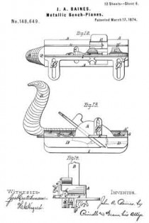
TONGUING AND GROOVING HAND-PLANE.

_________________

Specification of Letters Patent No. 17,541, dated June 9, 1857.

_________________

To all whom it may concern:

Be it known that I, PORTER A. GLADWIN, of Boston, in the county of Suffolk and State of Massachusetts, have invented an Improved Tongue and Groove Plane or “Match-Plane,” as usually termed; and I do hereby declare that the same is fully described and represented in the following specification and the accompanying drawings, of which —

Figure 1, is a side elevation of my improved plane. Fig. 2, a front end view of it. Fig. 3, a top view of it. Fig. 4, a front view of its plane iron or cutter. Fig. 5, is an end view, and Fig. G, a, side view of the ordinary match plane.

The common match plane is made with two separate throats for the reception of separate cutters, which are arranged so as to stand or slant in opposite directions as shown at a, and b, in Fig. 6.

In Fig. 5 c, and d, represent the vertical guides of the tonguing and grooving cutters, their lower edges being arranged on a level with each other while both of such guides are placed between the tonguing and grooving cutters. After the plane has been used to form a tongue it must be turned around or reversed in the hand in order to enable it to make a groove. This is not the case with my improved match plane which always works in one direction whether it be used for cutting a tongue or for making a groove.

In Figs. 1, 2, and 3, A, denotes the stock or body of the plane, which is constructed with a single throat, B, for the reception of a cutter, or plane iron C, formed as shown in front view in Fig. 4, that is, with a grooving cutting edge, i, and tonguing cutting edges, k, k, arranged with respect to one another as shown in said figure. This cutter, C, stands or slants in one direction and operates with vertical guides c’, d’, and horizontal guides f’, g’, h’, arranged as shown in Figs. 1 and 2.

In the common match plane, the vertical guides, c, d, (see Fig. 5) are arranged below the horizontal guides, and so that their lower edges may be on a level, whereas in my improved plane, the vertical guides, c’, d’, are arranged so that one of them viz d’ extends below the other, while the horizontal guide, f’, of the tonguing cutter is arranged between the said two guides, c’, d’. This latter arrangement enables the plane to be used with one handle and either for tonguing or grooving, while its handle is grasped by the hand of a workman, it not being necessary to reverse the plane during the performance of those operations.

The advantages of the improved match plane will be apparent.

I do not claim the combination of tonguing and grooving cutters, upright and horizontal guides in one stock, wherein the tonguing and grooving cutters are arranged to slant in opposite directions, but

What I do claim as an improvement in the match plane is,

The tonguing and grooving cutter or cutters in a single throat and to slant in one direction in combination with arranging the vertical guides so that one shall stand below the other, and the horizontal tongue guide be arranged between as specified.
In testimony whereof I have hereunto set my signature.

PORTER A. GLADWIN.

Witnesses:
R. H. EDDY,
F. P. HALE, Jr.