No. 1,032,346 – Plane (Edmund A. Schade) (1912)

[paiddownloads id=”684″]1032346


UNITED STATES PATENT OFFICE.

_________________

EDMUND A. SCHADE, OF NEW BRITAIN, CONNECTICUT, ASSIGNOR TO THE STANLEY RULE &
LEVEL COMPANY, OF NEW BRITAIN, CONNECTICUT, A CORPORATION OF CONNECTICUT.

PLANE.

_________________

1,032,346. Specification of Letters Patent. Patented July 9, 1912.
Application filed November 1, 1911. Serial No. 657,934.

_________________

To all whom it may concern:

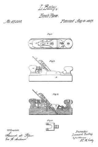
Be it known that I, EDMUND A. SCHADE, a citizen of the United States, residing at New Britain, county of Hartford, State of Connecticut, have invented certain new and useful lmprovements in Planes, of which the following is a full, clear, and exact description.

My invention relates to improvements in planes, and particularly to that type of plane in which the main body or stock is formed of wood.

My improvement aims at providing an improved construction for reinforcing the wood stock at the weakest point, namely, at the throat opening, where much of the wood is out away. Incidentally, but none the less important, the means for reinforcing the wood body cooperates in an improved manner with other new features of construction to hold the frog or cutter carrier seat securely in position.

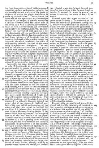
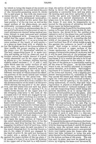
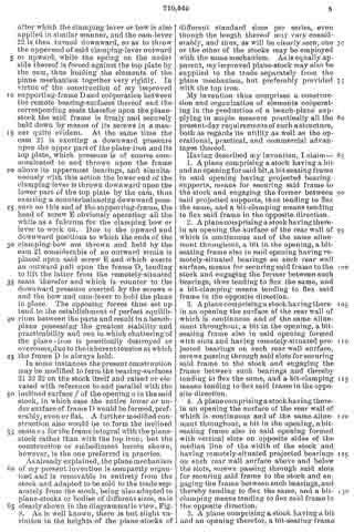
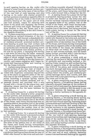
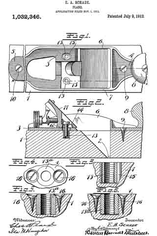
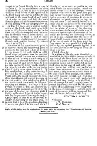
ln the drawings Figure 1 is a plan view of a part of a plane, constructed to embody my invention, the frog and plane iron being removed, the ends of the main reinforcement being broken away. Fig. 2 is a section on the line x–x Fig. 1, showing the cutter carrier, or frog, in place. Fig. 3 is a relatively enlarged sectional view of a detail of construction, on the section y–y Fig. 1. Fig. 4 is a plan view of a modification of the same detail. Fig. 5 is a sectional view of the modified detail shown in Fig. 4. Fig. 6 is a sectional view of still another modification of the same detail.

1 represents the main body or stock of a plane, the same being of substantial length, breadth and thickness, and being formed of wood. At an intermediate point in the length of the main body the stock is cut away down to the throat passage 2 to form a space for the plane iron and for the clearance of shavings. This cut-away portion always tends, in planes of this character, to substantially weaken the stock 1. To reinforce and strengthen said stock 1, I apply to the top side thereof a metal bracing or reinforcing piece of peculiar design, including a relatively wide plate 3 terminating in relatively narrowed-in extensions 4–5.

6–7 are integral upright reinforcing ribs bordering the sides of the reinforcing plate and bridging the plane iron passage in said plate and also in said stock. These ribs 6–7 give great rigidity to the reinforcing plate, so that when the same is properly secured to the stock 1, the weakened part thereof, as before pointed out, will be adequately strengthened so as to prevent all danger of breakage.

The usual hand grips may be provided at each end of the plane, the forward grip being shown at 8, the rear grip being omitted for want of room on the drawings.

Both ends of the reinforcing plate are secured to the wood stock 1 by means of screws 9–10. It is obvious that unless the middle portion of the reinforcing plate 3 is adequately secured to the stock, that the latter will not be properly braced. Hence I have provided means which not only serve to secure the plate at a middle point, between the screw fastenings 9–10, to the wood stock, but also serve to effectively hold the frog in any of the adjusted positions without strain upon the reinforcing plate.

11 represents the cutter support or frog, which in general is of well known design, and hence needs no detailed description. 12 represents the base of said frog. In this base, at each side, are provided screw-slots or passages, one of which appears in the upper portion of Fig. 1. Directly under these passages, and securely anchored in the wood stock 1, are cylindrical anchor blocks 13–13 drilled and tapped to receive the clamping screws 14, one of which appears in Fig. 2. The screws 14 pass through longitudinal slots in the frog, and enter the anchor blocks 13. These anchor blocks 13–13 may be shaped on the outside in any desired way, so long as they may be securely embedded and retained in the wood stock 1 in a rigid manner. For example, in the drawings, Figs. 1 to 3, each block 13 is shown as having an external coarse thread, which permits said block to be screwed into the wood stock 1. When said block is screwed down firmly in place, it is held against turning preferably by a pin 15, which acts as a key. The outer side of each block may have one or more vertical grooves or key-ways to permit one side of said key pin 15 to project partly into said anchor block when the latter has been screwed home.

ln Figs. 4 and 5, I have shown a slight modification of the anchor block, in which the outer wall thereof is unthreaded and arranged to be forced directly into a bore in the stock 1. In this modiiication the block is indicated at 13a and is held in place by means of wood screws 16, the upper end of the block being cut away or notched to permit part of the screw-head of each screw 16 to enter the notch and hold the block down in place and at the same time prevent it from turning with the clamping screw 14.

In Fig. 6, I have shown another modification of the block, said block being indicated at 13b, the same being similar to the block 13a with the exception that the outer side is provided with a coarse thread. In this instance the block is held in place against vertical displacement by the screw-threads and against turning by screws 16–16, as in Fig. 5.

The effect of this combination of parts is as follows: When the reinforcing plate is applied to the base 1, it is held at its ends by the screws 9–10, and, while an additional screw or screws may be provided whenever desired, the same are unnecessary, in view of the fact that when the frog 11 is in place and is clamped down by the screws 14, the drag of said screws tends to hold not only the frog 11 tightly on the reinforcing plate 3, but also holds the reinforcing plate 3 rigidly down upon the stock 1. By this arrangement, a long screw-bearing is provided for the clamping screws 14, as would not be the case if the screws 14; relied alone upon threads cut in screw passages on the comparatively thin reinforcing plate 3, for in such a case there would be danger of stripping the threads. Not only is it important to secure a firm and effective anchorage for the clamping screws 14 for the purpose of holding the clamping plate 3 tightly to the stock 1, but it is also important for the purpose of holding the frog 11 tightly upon its seat so as to prevent all danger of chattering of the plane iron. It is clear that it is of the greatest advantage to secure the plate 3 to the wood stock 1 directly at, or as near as possible to, the point where the strain occurs. Since the anchor blocks 13–13 are arranged closely adjacent to the rear of the plane iron passage in the reinforcing plate, it is obvious that a maximum of resistance to strains is adorded at this point, whereby the frog, top iron and stock 1 are securely braced at a point close to the mouth or cutter passage.

From the foregoing it will be observed that the plane of stress of the clamping screw or screws is always within the zone of resistance against upward movement of the means for holding the anchoring device, and it is also apparent that the plane of stress of said clamping screws is in advance of the rear fulcrum of the frog, hence the frog cannot by any possibility yield and chatter by any upward pressure applied to the front portion of the frog, as when the plane is in use.

What I claim is:

In a plane of the character described, a wood stock having a cutter passage extending through the same from the top to the bottom at a point intermediate its ends, an anchoring means rigidly embedded in said stock close to the rear of said cutter passage, means for holding said anchoring means from movement in any direction in said stock, a frog mounted on said stock at the rear of said cutter passage, and a clamping screw passing through said frog and arranged to screw into said anchoring means, said frog having a longitudinally slotted passage for said clamping screw to permit adjustment fore and aft, the plane of stress of said clamping screw being with-
in the zone of resistance to upward movement of the anchor holding means and forward of the rear fulcrum of said frog.

EDMUND A. SCHADE.

Witnesses:
I. W. CHAPMAN,
W. J. WORAM.

_________________

Copies of this patent may be obtained for five cents each, by addressing the “Commissioner of Patents, Washington, D. C.”
_________________

No. 746,285 – Plane (John W. Carleton And George E. Trask) (1903)

[paiddownloads id=”593″]746285


UNITED STATES PATENT OFFICE.

_________________

JOHN W. CARLETON AND GEORGE E. TRASK, OF NEW BRITAIN, CONNECTICUT,
ASSIGNORS TO THE UNION MANUFACTURING COMPANY, OF NEW BRITAIN, CONNECTICUT.

PLANE.

_________________

SPECIFICATION forming part of Letters Patent No. 746,285, dated December 8, 1903.
Application filed August 1, 1903. Serial No. 167,897. (No model.)

_________________

To all whom it may concern:

Be it known that we, JOHN W. CARLETON and GEORGE E. TRASK, citizens of the United States, residing at New Britain, in the county of Hartford and State of Connecticut, have invented certain new and useful Improvements in Planes, of which the following is a specification.

Our invention relates to improvements in planes; and the objects of our improvement are simplicity and economy in construction and convenience and efficiency in operation.

In the accompanying drawings, Figure 1 is side elevation of our plane. Fig. 2 is a central longitudinal section of the same, partly in elevation. Fig. 3 is a plan view of the same with the holding-cap, cap-iron, and cutting-bit removed. Fig. 4 is a side elevation of the middle portion of the iron frame of the stock. Fig. 5 is a side elevation of our plane when made with an iron stock without the wooden body. Fig. 6 is a sectional view of the same on the line x x of Fig. 5 when viewed in the direction of the dart in the said Fig. 5, the cutter being removed. Fig. 7 is a sectional side elevation of the middle portion of the stock and the adjusting-levers. Figs. 8 and 9 are plan and reverse plan views, respectively, of the cutting-bit with attached cap-iron and adjusting-nut, the same being adapted for use in both of the constructions herein shown. Fig. 10 is a plan view of the holding-cap and its screw.

A designates the wooden body, and B the iron frame, the said two parts together forming the stock of the plane. If desired, the wooden body A of the stock may be provided with a metal sole 5; but this is not essential. The frame B has an end plate 6 at its forward end provided with a hole for receiving the holding-screw 7 and also with a seat for the knob 8, the said seat being centrally perforated to receive the screw 9, that serves the double function of securing the said knob in place and of assisting to secure the said frame to the wooden body of the stock. At the rear end of the plate 6 there is a cross-rib 10, and extending rearwardly from the ends of the said cross-rib at opposite sides of the stock are the two side pieces 11 of the iron frame B, with the holding-lugs 12 on their confronting inner faces over the opening for the throat 13 of the stock. These side pieces 11 extend parallel to each other along the sides of the stock to a point in the rear of the middle of the length of the stock and then turn inwardly toward each other to the handle-seat 14 on the rear plate 15, near the end of which is the hole for the holding-screw 16. An ordinary handle 22 is secured to the handle-seat 14 by the rod 17, which is screw-threaded at its ends, one end being screwed into the threaded boss 18 on said handle-seat, while the other end is provided with the holding-nut 19.

The rear plate 15 extends forwardly to the side wings 20 of the frog, into which the said plate merges. An opening 21 is left in the rear plate between the said side wings 20 and rearwardly thereof. to near the handle 22. The side wings 20 of the frog are connected together near their upper ends by a bridge 23. The inclined front faces of the two side wings of the frog and the adjacent part of the rear plate form a seat for the cutting-bit in continuation of the inclined rear wall 24 of the throat of the stock. The side wings 20 of the frog are formed with a lug 25, Fig. 4, that extends below the base of the frame side pieces 11, and between these lugs we pivot a hub 26, having a short lever-arm 27 for engaging a slot in some device connected with the cutting-bit 28 or its cap-iron 29. The said hub is also provided with a longer lever-arm 33, that extends rearwardly from the hub for use as a handle in operating the said short lever-arm and cutting-bit for its endwise adjustment. Such levers of themselves, broadly speaking, are not of our invention. As shown, the short arm 27 of the lever engages a slot 36, Fig. 9, in the head of the screw 30, Fig. 2, which is held in the ordinary longitudinal slot of the cutting-bit 28 by means of the nut 31, the head of the said screw being shouldered by slabbing off on each side, as at 32, Fig. 2, so that the slabbed-off portion of the screw-head may enter the slot in the bit. On the upper face of the bridge 23 we pivot an ordinary laterally-adjusting lever 34. We secure the cutting-bit in place by means of a holding-cap C, the lower end of which is inserted under the confronting holding-lugs 12, after which the parts are tightened by turning in the holding-screw 35 at the upper end of the holding-cap C.

The stock Ba as shown in Figs. 5, 6, and 7, is wholly of iron and quite closely resembles the iron frame B, before described, only it is not adapted to have a wooden body secured thereto, and consequently its side pieces 11a are extended parallel to each other for nearly the whole length of the stock. These side pieces have on their inner faces the holding-lugs 12, before described. The side wings 20a of the frog are substantially the same as before described, only they are proportionally longer as the height of the inclined rear wall 24a of the throat 13 in the iron stock is less than in the wooden body of the stock first described. Like the side wings first described, a bridge 23 is provided to connect their upper ends. While there is an open space between the side wings 20a for pivoting the hub 26 of the lever 27 33, the pivot of the said lever comes higher up on the wings, and the lugs, which in the first-described construction project downwardly below the base of the wings, are omitted. The pivot-pin 37 for the hub 26 may for convenience of heading it pass through the side pieces 11a as well as the wings 20a The cutting-bit and connected parts and both of the adjusting-levers are the same as first described and have the same reference-numerals.

We claim as our invention —

1. In a plane, the frame of the stock having the side pieces 11, a frog between the said side pieces having the side wings with open space between, and the bridge 23 connecting the upper corners of the said side wings, which bridge forms a support for the laterally-adjusting lever.

2. In a plane, the stock having the side pieces, a frog between the said side pieces having the side wings with open space between, a bridge connecting the upper ends of the said side wings and forming a support for a laterally-adjusting lever, and an adjusting-lever consisting of a hub, short arm and longer operating-arm, the same being pivoted in the open space between the lower part of the said side wings and in front of the said bridge, with the body of said operating-arm working between the said wings while its handle end extends under the said bridge beyond the said wings at the rear thereof.

3. The herein-described plane, comprising the wooden body and iron frame of the stock, the said frame having the front and rear plates, connecting side pieces, and the frog between the said side pieces having the side wings with open space between and bridge at their upper corners forming a support for the laterally-adjusting lever.

4. The herein-described plane, comprising the wooden body and iron frame of the stock, the said frame having the front and rear plates with knob and handle seats, side pieces connecting the said plates and the frog between the said side pieces, the said frog having the side wings with open space between, the inclined front faces of the said side wings and the adjacent part of the said rear plate forming a direct seat for the cutting-bit, while the lower parts of the said side wings form a support for the longitudinaliy-adjusting lever.

5. The herein-described plane, comprising a wooden body and frame of the stock, the said frame having front and rear plates, connecting side pieces with the confronting holding-lugs on their inner faces, a frog between the said side pieces having the side wings with open space between, a bridge at the upper corners of the said wings forming a support for a laterally-adjusting lever, and lugs at the lower corners of the said wings for the longitudinally-adjusting lever.

6. In a plane, the stock having side pieces, a frog between the said side pieces composed mainly of a pair of inclined side wings with open space between, and aconnecting-bridge 23, at the upper ends of the said side wings that spans the said open space between them, the said side pieces forming a support for the longitudinally-adjusting lever and the said bridge forming a support for the laterally-adjusting lever, substantially as described.

7. In a plane, the stock having side pieces, a frog between the side pieces having the side wings with open space between, a longitudinally-adjusting lever with its long and short arms pivoted between the said side wings with the upper end of the said long arm projecting rearwardly from the space between the said side wings, a bridge connecting the upper ends of the said side wings, and a laterally-adjusting lever pivoted on the said bridge.

JOHN W. CARLETON.
GEORGE E. TRASK.

Witnesses:
JAMES SHEPARD,
SHEFFIELD H. CLARKE.

No. 715,352 – Plane (Lewis M. Curry) (1902)

[paiddownloads id=”575″]715352


UNITED STATES PATENT OFFICE.

_________________

LEWIS M. CURRY, OF BRIGHTON , MICHIGAN.

PLANE.

_________________

SPECIFICATION forming part of Letters Patent No. 715,352, dated December 9, 1902.
Application filed March 29, 1902. Serial No. 100,512. (No model.)

_________________

To all whom it may concern:

Be it known that I, LEWIS M. CURRY, a citizen of the United States of America, residing at Brighton, in the county of Livingston and State of Michigan, have invented certain new and useful Improvements in Planes, of which the following is a specification, reference being had therein to the accompanying drawings.

My invention relates to improvements in carpenters’ planes; and its object is to provide a cheap and simple construction which is strong and durable, having few parts, easily assembled, and not liable to get out of order, and to provide ready means for accurately adjusting the plane-bit longitudinally within the throat and to so construct the parts as to allow for a slight lateral adjustment of the bit, it also being the object of this invention to provide means for clamping the bit and its shavings-breaker to the support therefor, so that they are firmly held without the necessity of a clamping-plate or other obstruction on the upper side of the breaker, and the bit will be frictionally held against accidental lateral movement thereby, but may be so adjusted by the operator.

To this end the invention consists in providing a longitudinally-movable carrier for the bit, which carrier is supported at an inclination substantially the same as that of the bed and free to move laterally on its support, and in providing suitable means for securing the bit to the carrier at one end, which means also serves to hold the lower end of the bit in strong frictional contact with the bed to prevent such lateral movement of the bit except when adjusted by the operator; and the invention further consists in providing suitable mechanism for moving the carrier and attached bit longitudinally to regulate the cut, and also in the particular construction, arrangement, and combination of parts, all as more fully hereinafter described, reference being had to the accompanying drawings, in which —

Figure l is a perspective view of a device embodying my invention; Fig. 2, a longitudinal vertical section through the bit and adjacent parts and a portion of the stock on the line 2 2 of Fig. 3. Fig. 3 is a section on the 2, showing a plan view of the line 3 3 of Fig. 2; Fig. 4, a section on the line 4 4 of Fig. 2, showing the carrier in plan; Fig. 5, the same, showing the carrier in section and illustrating the manner in which the bit is adjusted laterally; and Fig. 6 is a longitudinal vertical section similar to Fig. 2, showing a modified adjustment for the carrier and showing the bit unclamped to illustrate the manner in which it is held against the bed.

A is the stock of the plane, formed, in the usual manner, of hard wood, with a throat A’, having the mouth A2, and one side extended at an inclination of about forty-five degrees to form the bed A3, upon which the bit-iron or knife rests.

B is a casting secured to the top of the stock and provided with upwardly-extended supporting flanges or sides B’, which form bearings for the transverse pin C and eccentric-rod D, which support the bit-carrier E. Said carrier E consists of a rectangular casting having its middle portion cut away to lighten the same and provided with a lug E’, projecting from its lower end, which lug has an elongated opening E2 or slot through which the pin C extends, and through a transverse opening E3, near its upper end, extends the eccentric-rod D, which rod is provided with bearing ends D’ and D2 to engage the bearings in said sides B’. The rod D is set eccentrically to its bearing ends, so that when the same is turned by the knurled head D3, which is secured on the outer end of the reduced portion D4, the carrier will be moved a distance equal to the throw of said eccentric, and to secure the eccentric in place and connect the sides B’ a yoke F is provided, which embraces the sides B’ and is secured at its lower ends by the pin C, which extends therethrough and is riveted at its outer ends and near the top of the sides by the screws F’, said yoke extending over and closing the outer end of the opening forming the bearing for the end D’ of the eccentric and has an opening to at the reduced portion D4, thus securing the eccentric in place and forming a brace for the sides B’.

The knife or bit-iron G and its cap-iron or shavings-breaker H are secured together in the usual manner by a set-screw H’ engaging a slot G’ in the bit. The breaker is nearly as long as the bit and is provided with openings H2, having lateral extensions H3, located opposite the slot G’, to receive the heads of the screws I and J, which screws engage screw-threaded openings I’ and J’ in the carrier E, the head of the screw I forming an abutment to engage the upper side of the breaker.

The carrier E is supported at substantially the same inclination as the inclination of the bed A3, and the screw I is adjusted to bring its head at such a height relative to the bed that when said head is passed through the openings H2 and the breaker moved to engage the extension H3 with the shank of the screw the lower end of the bit will engage the bed adjacent to the mouth.

A binding-screw K engages a screw-threaded opening K’ in the carrier E, and on the inner end of said screw is a head K2, a recess K3 being provided in said carrier for said head, which head is forced upward by the turning of the screw into engagement with the under side of the bit and forces the lower end of the bit against the bed, the screw J being properly adjusted relative to the screw I to form a stop to prevent the bit from being bent too far by the action of the screw. The turning of the binding-screw K thus not only secures the bit to the carrier, but forces the same into frictional contact with the bed by the spring of the said bit, and by adjusting the screws I and J the frictional contact may be increased or diminished and the angle of the bit changed, so that it will lie flat upon the bed or will contact the same only at its lower end.

The carrier is made somewhat narrower than the space between the sides B’, and the eccentric is made to have a little play in its bearings, so that said carrier may be shifted laterally. When the bit is in place, the frictional contact thereof with the bed will hold the lower end of the bit so that when the upper end of the carrier is shifted the bit will be tilted to bring its cutting edge even with the sole of the stock when the bit is not ground exactly true, as shown in Fig. 5, and the spring action of the bit and its breaker causes a friction on the eccentric D, so that it will not be accidentally turned.

If desired, an adjusting-screw L, passing through an opening in the yoke F and engaging screw-threaded openings in the carrier, may be provided to move the carrier instead of the eccentric D; but I prefer said eccentric, as it is more accurate, is simple, cheap, and more durable.

Having thus fully described my invention, what I claim is —

1. In a plane, the combination with the stock; of side flanges on said stock, a bit, a movable carrier to which the bit is secured, and means supported by said flanges for supporting and moving the carrier to adjust the bit.

2. In a plane, the combination with the stock; of side flanges on said stock, a laterally-movable bit-carrier, a bit secured to said carrier, and means on the flanges for supporting the carrier and upon which it may be moved laterally of the stock to tilt the bit.

3. In a plane, the combination with the stock; of side flanges on said stock, a bit-carrier supported by said flanges and adapted to be moved laterally between the same, a bit on said carrier, and means for securing said bit to the carrier and for causing a frictional resistance to such lateral movement of the carrier.

4. In a plane, the combination with the stock; of a bit adapted to be moved longitudinally, side flanges on said stock and an eccentric supported by said flanges and adapted to move said bit.

5. In a plane, the combination with the stock thereof having a bed; of a carrier supported upon said stock and provided with screw-threaded openings a bit having an opening and engaging said bed at one end, a screw engaging one of the openings in the carrier and projecting through said opening in the bit to engage its head with the upper side of said bit, and a binding-screw engaging the other opening in the carrier and contacting the under side of said bit.

6. In a plane, the combination with the stock and a bit thereof; of supporting-flanges on said stock, a carrier to which the bit is secured, supported by said flanges to move longitudinally and provided with a transverse opening, and an eccentric within said opening.

7. In a plane, the combination with the stock thereof; of supporting-flanges on said stock, a carrier having a slot and a transverse opening, a pin supported by the flanges and engaging said slot, a rod in said opening having eccentric ends engaging bearings in said flanges, a bit, and means for securing said bit to said carrier.

8. In a plane, in combination a stock having a bed, supporting-flanges on said stock, a carrier having a slot at its lower end and a transverse opening near its upper end and screw-threaded openings, a pin secured at its ends to the supporting-flanges and extended through said slot, a rod in the transverse opening and having eccentric ends engaging bearings in the flanges, and provided with a head, a bit having openings, screws having heads projecting through said openings and engaging the upper side of the bit and adjustable in the screw-threaded openings in the carrier, a binding-screw extending through said carrier and a head on said binding-screw engaging said bit.

9. In a plane, the combination of a stock a casing secured to the upper side of said stock, the supporting-flanges on said casings having openings, a longitudinaily-movable carrier having a slot and a transverse opening, a pin extending through the opening in the flanges and the slot in the carrier, a rod engaging the transverse opening in the carrier and provided with eccentric ends engaging bearings in said flanges and having a reduced portion provided with a knurled head, a yoke embracing the flanges and provided with an opening to receive the reduced portion of the eccentric, and a bit secured to said carrier.

In testimony whereof I affix my signature in presence of two witnesses.

LEWIS M. CURRY.

Witnesses:
LEWIS E. FLANDERS,
OTTO F. BARTHEL.

No. 710,678 – Plane (Charles H. Fox) (1902)

[paiddownloads id=”574″]710678


UNITED STATES PATENT OFFICE.

_________________

CHARLES H. FOX, OF NEW BRITAIN, CONNECTICUT, ASSIGNOR TO
THE STANLEY RULE & LEVEL COMPANY, OF NEW BRITAIN, CONNECTICUT,
A CORPORATION OF CONNECTICUT.

PLANE.

_________________

SPECIFICATION forming part of Letters Patent No. 710,678, dated October 7, 1902.
Application filed December 31, 1901. Serial No. 87,942. (No model.)

_________________

To all whom it may concern:

Be it known that I, CHARLES H. FOX, a citizen of the United States, residing in New Britain, in the county of Hartford and State of Connecticut, have invented certain new and useful Improvements in Planes, of which the following is a specification.

This invention relates to bench-planes; and it consists, substantially, in the improvements hereinafter more particularly described.

Without attempting to enumerate the advantages of the present invention by comparison with other planes hitherto devised it may be stated that the present invention has for its object to provide a plane of simple and effective construction and organization and one in which the plane mechanism is economically and compactly seated in place upon the stock in such manner as to overcome or prevent any tendency to chattering ot the operative portion of the plane-iron, and also to provide an extended bearing for the rear or under side of the supporting-frame of the plane mechanism, and to greatly strengthen the fastening for such frame without materially adding to the weight of the plane.

A further object is to provide means for preventing dislodgment or disorganization of the plane mechanism either in part or in entirety due to any tendency thereof to rise from its seat upon the stock, from drag upon the plane-iron, or from other causes.

A still further object of the invention is to provide means for fastening the supporting-frame to the stock in the most. rigid and secure manner, while readily permitting vertical or up and down adjustments of such frame for the purpose of effecting changes in the position of a wearing-sole in conformity with the needs thereof, and also to provide means whereby the up and down adjusting devices for the plane-iron are housed in part and protected against accidental displacement in the use of the plane.

The above and additional objects are attained by means substantially such as are illustrated in the accompanying drawings, wherein —

Figure 1 is a longitudinal sectional elevation of a plane embodying my improvements, said view being taken just to one side of the median line of the width of the stock, several of the parts being shown in elevation. Fig. 2 is a top or plan view thereof with the plane mechanism removed. Fig. 3 is a central longitudinal sectional view of the top iron of the plane. Fig. 4 is an enlarged view similar to Fig. 1 to more clearly indicate the construction and organization of parts or elements comprising or constituting the plane mechanism, the stock or body of the plane being broken off at each end. Fig. 5 is also a similar view taken to one side of the median line of the width of the stock and just to the outer side of one of the fastening-screws for the frame of the plane mechanism, so as to clearly show the construction and organization. Fig. 6 is a view looking at the rear or under side of the supporting-frame for the plane mechanism, said plate being minus any of such mechanism as well as the adjusting elements for the plane-iron; and Fig. 7 is a view looking at the front or upper side of the supporting-frame, the stock and top iron being shown in vertical section and the laterally-adjusting lever for the plane-iron being partly broken off.

Before proceeding with a more detailed description it may be stated that in the practice of my invention I provide the body or stock of the plane of any suitable wood, and I form therein from top to bottom an opening the surface of the rear wall of which is inclined to provide a seat of proper angle or inclination for the plane-iron mechanism and the surface of the front wall of which is specially constructed at the bottom of the stock to cooperate with the lower end of the frame of the plane mechanism, as and for the purpose hereinafter specifically explained. To provide an extended and continuous bearing-surface for the supporting-frame of the plane mechanism, I extend the rearwardly and upwardly inclined surface of the rear wall of the opening in the stock some distance above the top of the stock, and preferably such extension is in duplicate with the parts thereof on opposite sides of the median line of the width of the stock. The supporting-frame is provided separately with some suitable laterally and vertically adjusting devices for the plane-iron, and the said plane-stock and supporting-frame are so constructed that the principal parts of the said vertically-adjusting devices are snugly and conveniently housed in such manner as not to become broken or disarranged accidentally while the plane is in use, yet readily accessible for adjusting or changing the position of the plane-iron. Preferably the upward extensions of the surface of the rear wall of the opening in the stock are of metal, constituting integral parts of the plane-iron, and the supporting-frame of the plane mechanism is provided with a sole or wear plate receiving the wear of the plane and havinga throat for the play of the operative end of the plane-iron. The supporting-frame is also otherwise specially constructed at its lower end to cooperate with the said specially-constructed part of the surface of the front wall of the plane-opening to prevent uprising or dislodgment of said frame and the other parts of the plane mechanism supported or carried thereby, and preferably, also, the fastenings for the frame are introduced into the said duplicate metal extensions of the rear surface of the opening of the stock rather than in the stock itself. The construction enables use to be made of plane stocks or bodies of comparatively limited height and is otherwise especially advantageous, both from a commercial and practical point of view.

Specific reference being had to the accompanying drawings, wherein an embodiment of my invention is shown and which maybe the preferred embodiment, A represents the stock or body of the plane, constructed of any suitable wood for the purpose and formed therein at the proper point of its length with an opening a, the surface b of the rear wall of which is rearwardly and upwardly inclined at an angle of about forty-five degrees (45°) to the base of the plane, so as to give to the plane mechanism seated upon such surface the proper inclination within such opening. The lower corner of the front wall c of said opening a is also cut off or beveled to produce a similarly-inclined shorter surface d, which is preferably parallel with the said surface b, for the purpose hereinafter understood. In the top surface thereof the said plane stock or body is cut out or recessed a short distance centrally thereof, so as to provide a cavity e, leading rearwardly from the opening a and designed to partially receive the operating element of the up and down adjusting devices for the plane-iron in the manner shown and as hereinafter specifically set forth. Secured in place upon the upper portion of the stock or body by means of screws or similar fastenings f is the top iron B, which is constructed with parallel and slightly raised or elevated side portions g g, the inner surfaces of which may be practically flush or even with the corresponding surfaces of the sides of the opening a, already referred to. Said side portions g g are united by an integral rib h, connecting the same at about the upper forward edge of said opening a, and forwardly of said rib the said top iron is formed with a short longitudinal extension i, on which is seated the knob or forward handle j of the plane, said knob being held in place by a screw k, entering the stock through a suitable opening therefor in said forward extension. The rearward ends of the side portions g g of the top iron gradually decrease in height and slightly converge at l l, whence they terminate in parallel elevated flanges m m, formed on a rearward longitudinal extension n, and upon which latter, between said flanges, is seated the base o of the main or rear handle C of the plane, said handle being securely fastened in place by a screw-rod p, passing through the same and secured at its lower end in a threaded opening in the said extension n therefor. The forward part of said rearward extension it of the top iron is cut out or notched at n’, so as to bring the inner edges e’ thereof about even with the side and rearward edges of the recess or cavity e of the plane-stock, and thus are formed the integral flanges s s of the top iron, which are seated upon the upper surface of said stock on opposite sides of the said recess or cavity therein. Said flanges are each provided with a hole or opening for the passage of a screw t, which enters the stock on opposite sides of the median line of the width of the same, and thus is an extremely rigid and compact structure derived. Said side flanges s s of the top iron are each widened somewhat at s’, and they also constitute bases for preferably duplicate integral supports u u for the frame D of the plane mechanism E, said supports of course being also on opposite sides of the median line of the width of the plane and being integral at the outer sides thereof with the adjacent inner surfaces of the rear ends of the side portions g g of the top iron. In this way increased width or thickness of each of the said supports it is obtained for the formation therein of a threaded opening v for the reception of a screw w for securing the supporting-frame D in place and which construction does not materially add to the weight of the plane. The forward edges or faces x x of said supports u u are faced off in the same plane and at an upward and rearward inclination corresponding to the angle of inclination of the surface b of the rear wall of opening a in the stock, and thus said faces of the said supports constitute practical upward continuations or extensions of said surface b. In this way an increased, even, and continuous bearing-surface is obtained for the under side of the supporting-frame D of the plane mechanism, as is obvious. The frame D is substantially a rectangular plate the upper part d’ of which is comparatively thin, while the remaining lower portion thereof is of increased thickness, for the purpose hereinafter understood, although recessed or hollowed out, as at y y, on its upper surface, so as to lessen the weight thereof as much as possible without any less of strength. At its lower end the said supporting-frame is formed or provided with a sole d2, in which is formed transversely a throat d3 for the player working of the lower and operative end of the plane-iron F in a manner well known. Also formed with said frame and preferably on the upper part of said sole-plate forwardly of the throat therein is a wedge G, the forward surface of which is at a corresponding angle to the undercut or beveled portion d of the surface of the front wall of the said opening a in the stock. Formed on the under side of the frame D, about centrally thereof, is a pendent or hanging portion d5, having in its rear face a threaded opening in which works the inner end of an adjusting-screw d4, having thereon an operating-button d5, provided with collars 1 1, forming between them a circumferential groove 2, in which are received on opposite sides of said screw the ends of the furcated arm 3 of a swinging lever 4, having its bearing on a rod or pin 5 between short flanges 6 6, also formed on the under side of said frame, the end or nose of the shorter arm 7 of such lever protruding forwardly through an adjacent opening or slot 8 in the said frame, all as shown. The said elements constitute the usual or well-known vertical or up-and-down adjusting devices for the plane-iron F, and it will be seen that the same are brought to a comparatively low position with reference to the plane-stock, the operating-button d5 thereof extending partly into the cavity e of the stock, thus economizing greatly in the space consumed or occupied by said devices as a whole. Moreover, in virtue of the lower part of the frame D being of an increased thickness downwardly, beginning at a point somewhat below the point of suspension of the lever 4 thereon, said adjusting devices are thus carried forwardly a distance about equaling the difference of thickness between the two parts of said frame, and are thereby caused to be snugly housed in the space between the inclined extended bearings or supports u u. In this way the operation of the adjusting devices in question may be effected without difficulty, while at the same time they are prevented in large measure from breakage or disarrangement by contact with external objects in the handling of the plane. Above the opening or slot 8 in the upper part of frame D is a recess 9, in which works a button 10, carried on the end of the well-known form of laterally-adjusting lever 11 for the plane-iron pivoted at 12 on the frame, the said button engaging, as usual, the sides or edges of a longitudinal slot or opening 13 in said plane-iron. Screwing in to the said supporting frame or plate D ofthe frame mechanism, about centrally of the width thereof and at a point about corresponding to the upper surface of the plane-stock, is an upwardly and forwardly projecting screw 15, over which is fitted the plane-iron F, having secured thereto by means of screw 16 the ordinary top plate F2, and above the top plate and also fitting ever the screw by means of an opening or slot 17 therein is the usual clamping device or lever 18, with the edges of the said slot therein engaging under the head of said screw, the parts all being held together within the opening a of the stock by the clamping action of said clamping-lever 18 caused by the cam 19 when turned down against the top plate by means of its operating-lever 20, the said cam bearing directly upon a spring 21, secured on the under side of said clamping-lever and all operating in an obvious manner. Formed in the said supporting frame or plate D, on either side of the median line of the width thereof, are the slots er openings 25, the lower edge of each of which is substantially in the plane of the longer axis of screw 15, and the length of each of which is only suflicient for maximum vertical or up-and-down adjustments of the frame, whereby the sole d2 at the lower end thereof may be carried to any extent of protrusion beyond the under or wearing surface of the stock by which to practically receive and sustain the greater part of the wear of the plane in use. Said slots or openings 25 are also in direct line with the screw-holes v v in the extensions or supports u u, the original position of such openings prior to any adjustment of the frame being about midway the length of the slots, substantially as shown in Figs. 4 and 5, and the frame is chamfered or countersunk at 27 around the edges of said slots, so as to bring the heads of the fastening-screws w for the frame at least flush with or below the upper surface of the latter, and thereby enabling an even seating of the plane-iron upon said frame. From the construction and organization shown and described it will be seen that the fastening-screws w for the frame D are brought into the nearest practical proximity or relationship with the said forwardly-projecting screw 15, and thus is there partially established a counterbalance between the opposing forces acting separately on said screw 15 and the screws w, the one force tending to pull the frame outwardly or upwardly and the other tending to hold the frame (and consequently the entire frame mechanism) down upon its seat or bearing upon the stock within the opening a therein. Inasmuch, however, as the pressure or force exerted by cam 19 as well as that exerted by screws w are both on the same side of and above screw 15, which latter it will be understood is a fulcrum for the clamping bow or lever 18, there is a slight tendency to uprising of the lower end of the frame D, which tendency is successfully or effectually resisted by the forward inclined face of the wedge G firmly abutting or engaging the opposing inclined surface d of the lower part of the front wall of the said opening a, in the stock. In this way there is established a most perfect counterbalance or equilibrium of the forces acting upon the parts of the planes in different or opposing directions, thereby overcoming or preventing any tendency to vibration or chattering of the plane-iron irrespective of the degree of hardness of the wood upon which the plane is used.

It will be seen from the foregoing description, taken in connection with the accompanying illustrations, that I have provided a bench-plane possessing compactness and stability and one in which adjustments may be made readily and accurately without loss of time. The plane is strong and capable of withstanding all the handling incident to the conditions under which the same may be used, and the general commercial as well as practical advantages thereof will be apparent without further mention. It will be understood, of course, that I do not limit myself to the precise details of construction and organization of the elements of the plane, since changes may be made therein without departing from the spirit and scope of my invention.

Having described my invention, I claim —

l. A plane-stock with an opening therein having duplicate upward extensions of the surface of the rear wall thereof, such surface being of the same alinement throughout and the extensions thereof directly continuous therewith, a supporting-plate for a plane-iron seated within the opening, and fastenings for said plate entering said surface extensions.

2. A plane-stock with an opening therein the surface of the rear wall of which is rearwardly and upwardly inclined and provided with duplicate upward extensions thereof, such surface being of the same alinement throughout and the extensions thereof directly continuous therewith, a supporting-plate for a plane-iron seated within the opening, and fastenings for said plate entering said surface extensions.

3. A plane-stock with an opening therein the surface of the rear wall of which is rearwardly and upwardly inclined and provided on opposite sides of the median line of the width of the stock with duplicate upward extensions thereof, such surface being of the same alinement throughout and the extensions thereof directly continuous therewith, a supporting-plate for a plane-iron seated within the opening, and fastenings for said plate entering said surface extensions.

4. A plane-stock with an opening therein the surface of the rear wall of which is rearwardly and upwardly inclined and of the same alinement throughout, and a top iron secured to the stock and formed with duplicate directly-continuous extensions of such surface, a supporting-plate for a plane-iron seated within the opening, and fastenings for said plate entering said surface extensions.

5. A plane-stock having therein an opening the surface of the rear wall of which is rearwardly and upwardly-inclined and of the same alinement throughout, and the lower part of the front wall of which is undercut in parallelism therewith, said stock being provided with a top iron having duplicate directly-continuous extensions of such rear-wall surface, a supporting-plate for a plane-iron seated within the opening, and fastenings for said plate entering said surface extensions.

6. A plane comprising a stock having an opening therein the surface of the rear wall of which is rearwardly and upwardly inclined and of the same alinement throughout, a top iron having directly-continuous duplicate extensions of such surface located on opposite sides of the median line of the width of the plane, a plane mechanism having vertically-adjusting devices for the plane-iron housed between the extensions, and means securing the supporting member of said plane mechanism to the faces of said extensions, said means entering said extensions at the said faces thereof.

7. A plane comprising a stock having an opening therein the surface of the rear wall of which is rearwardly and upwardly inclined and of the same alinement throughout, said stock being also formed in the top thereof with a cavity extending rearwardly of said opening, a top iron having directly-continuous duplicate extensions of the rear-wall surface of the stock-opening on opposite sides of the median line of the width of the plane, a plane mechanism comprising a supporting-frame provided on the under side of the upper portion thereof with vertically-adjusting devices for the plane-iron, said supporting-frame resting upon such rear-wall surface and its extensions, and secured to the latter, and also being of increased thickness below the point of suspension of the adjusting devices thereon, whereby such devices are brought to a housed position between the duplicate extensions and partially received in the cavity in the stock.

8. A plane comprising a stock having an opening therein the surface of the rear wall of which is rearwardly and upwardly-inclined and of the same alinement throughout, said stock being also formed in the top thereof with a cavity extending rearwardly of said opening, a top iron having directly-continuous duplicate extensions of the rear-wall surface of the stock-opening on opposite sides of the median line of the width of the plane, a plane mechanism comprising a supporting-frame having duplicate slots and provided on the under side of the upper portion thereof with vertically-adjusting devices for the plane-iron, said supporting-frame resting upon such rear-wall surface and its extensions, and also being of greatest thickness below the point of suspension of the adjusting devices thereon whereby such devices are brought to a housed position between the duplicate extensions and partially received in the cavity of the stock, and screws passing through the slots of said frame and entering the openings therefor in the said extensions.

9. A plane comprising a stock having an opening therein the surface of the rear wall of which is rearwardly and upwardly inclined and of the same alinement throughout, and the lower part of the surface of the front wall of which is undercut in parallelism with such inclined surface, said stock being also formed in the top thereof with a cavity extending rearwardly of said opening, a top iron having directly-continuous duplicate extensions of the rear-wall surface of the stock-opening on opposite sides of the median line of the width of the plane, a plane mechanism comprising a supporting-frame having duplicate slots and provided on the under side of the upper portion thereof with vertically-adjusting devices for a plane-iron, said supporting-frame resting upon such rear-wall surface and its extensions and provided with a sole formed with a throat and having a wedge engaging such undercut surface, and also being of increased thickness below the point of suspension of the adjusting devices thereon, whereby such devices are brought to a housed position between the duplicate extensions and partially I received in the cavity in the stock, and screws passing through said slots and engaging the extensions.

10. A plane comprising a stock with an opening therein the surface of the rear wall of which is rearwardly and upwardly-inclined and provided with duplicate extensions beyond the top of the stock on opposite sides of the median line of the width thereof, the surface of the front wall of which opening is undercut all the way across the stock at the bottom in parallelism with such inclined surface, and a vertically-adjustable plane mechanism including a supporting-frame seated within the opening and slotted on opposite sides of the median line of the width thereof, and screws passing through the slots of the frame and entering said extensions, said frame being provided at its lower end with a sole formed with a throat for the plane-iron and having a wedge engaging such undercut surface, such rear-wall surface being of the same alinement throughout and the extensions thereof directly continuous therewith.

CHARLES H. FOX.

Witnesses:
H. S. WALTER,
W. J. WORAM.

No. 710,542 – Bench-Plane (Justus A. Traut) (1902)

[paiddownloads id=”573″]710542


UNITED STATES PATENT OFFICE.

_________________

JUSTUS A. TRAUT, OF NEW BRITAIN, CONNECTICUT, ASSIGNOR TO
THE STANLEY RULE & LEVEL COMPANY, OF NEW BRITAIN, CONNECTICUT,
A CORPORATION OF CONNECTICUT.

BENCH-PLANE.

_________________

SPECIFICATION forming part of Letters Patent No. 710,542, dated October 7, 1902.
Application filed December 28, 1901. Serial No. 87,532. (No model.)

_________________

To all whom it may concern:

Be it known that I, JUSTUS A. TRAUT, a citizen of the United States, residing in New Britain, in the county of Hartford and State of Connecticut, have invented certain new and useful Improvements in Bench-Planes, of which the following is a specification.

This invention relates to bench-planes; and it consists, substantially, in the improvements hereinafter more particularly described.

Considerable attention has been given in recent years to the construction and operation of bench-planes (both metal planes and wooden planes) with a view to increasing the general effectiveness and range of efficiency thereof, and more especially to the construction and organization of the elements or parts constituting the operative mechanism of the plane, as well as to the manner of seating and securing such mechanism within or upon the plane stock or body. Principal among the difficulties encountered in planes usually is the undue vibration or chattering of the edge or operative portion of the plane-iron, due largely to the drag or upward resistance offered by the surface of the wood operated upon, particularly in the case of hard woods. To overcome such chattering in a metal plane, it has been suggested to provide the upper surface of the sole of the plane with two steps, one raised or elevated above the other and the two constituting remotely-situated step-bearings for a so-called “frog” firmly held upon said bearings and flexed to thereby steady the same, and thus prevent chattering of the plane, while still permitting of adjustments of the plane-iron for varying the width of the throat of the plane. As is obvious, a construction or organization of the kind mentioned is not practicable with a plane having a wooden body; but, as hereinafter specifically explained, practically the same resuits are attained in a wooden plane by means of substantially the construction and organization of devices herein employed. Other difficulties and disadvantages have also been frequently met with in the construction and operation of the adjusting elements of the operative mechanisms of planes generally, I (both metal and wooden planes,) since in many embodiments hitherto devised or employed it is always diflicult and often practically impossible to effect the adjustment of one of such parts or elements without disarranging or dislocating the whole or some other part or parts of the mechanism and which is a decided objection for several reasons. Still further, in many instances hitherto the so-called “wooden planes” are both heavy for convenient use and comparatively expensive to manufacture on account of the considerable arnount of material employed in the construction of the essentially metallic portions thereof, and for which and other reasons the commercial advantages of the plane are greatly lessened as well as its utility.

The present invention has for its object to overcome all of the above-mentioned difficulties and disadvantages and to provide a bench-plane possessing the greatest stability between the several elements or parts thereof and also in which each part or element combines maximum strength with extreme lightness and delicacy of structure.

A further object is to greatly improve this class of tools generally, both from a commercial as well as from a practical standpoint, whereby the cost of the plane is reduced and the effectiveness and efficiency of the same enhanced over and above many planes hitherto devised with similar ends in view.

A further object of the present invention is to provide simple and effective means for preventing chattering of the operative portion of the plane-iron and also to provide a plane mechanism of great stability and compactness and one in which the up and down adjusting devices for the plane-iron may be set to any position desired irrespective of whether the said mechanism is in place within or upon the plane body or stock.

A still further object is to provide a plane mechanism adapted for use with plane stocks or bodies of dilferent standard sizes without requiring any change either in the adjustment or fastening of any of the elements thereof, all as will more fully hereinafter appear.

The above and additional objects are attained by means substantially such as are illustrated in the accompanying drawings, wherein —

Figure 1 represents a longitudinal vertical sectional elevation of a bench-plane embodying my several improvements, said view being taken substantially on the median line of the plane. Fig. 2 is a top plan view of my improved bench-plane with the operative mechanism thereof detached or removed to more clearly indicate the construction of the plane-stock, as well as the inclined seats or supports which receive and cooperate with the uppermost projections or raised bearing-surfaces on the rear or under side of the adjustable supporting-frame of said operative mechanism. Fig. 3 is a longitudinal sectional view of the top iron of the plane, taken about centrally. Fig. 4 is an enlarged sectional view of my improved bench-plane, taken about on the same line as in Fig. 1, the stock or body of the plane being broken off at the ends. Fig. 5 is a view looking from the rear or under side of the adjustable supporting-frame for the operative mechanism of the plane (appurtenances being removed) to more clearly indicate the arrangement and location of the projections or raised bearing-surfaces on said frame. Fig. 6 is a sectional view on the line X X of Fig. 7 to indicate more clearly one of the slots and screws or similar fastenings by which the adjustable frame of the plane mechanism is confined in place upon the seats therefor, said view being minus the plane-iron and its adjusting devices, as well as the top plate and clamping bow or lever shown in Figs. 1 and 4. Fig. 7 is a vertical transverse sectional view looking toward the right of Fig. 1 and being partly broken away at one side to indicate one of the screw-holes in the plane-stock and also being minus the forwardly-adjusting device for the plane-iron, as well as said latter element and the top plate and clamping bow or lever shown in Figs. 1 and ft. Fig. 8 is a diagrammatic view illustrative of the adaptation of my improved plane mechanism to plane bodies or stocks of different sizes or dimensions.

Before proceeding with a more detailed description it may be stated that in carrying my invention into effect I provide the body or stock of the plane of any suitable wood adapted to the purpose, and I form therein an opening extending from top to bottom thereof for the reception of the operative mechanism of the plane, which mechanism comprises suitable ordinary adjusting devices for the plane-iron both in vertical and lateral directions. The said operative mechanism also includes an adjustable supporting-frame constructed with a sole-plate in which is formed the throat for the proper working of the cutting edge of the bit or plane-iron, and said sup porting-frame is otherwise constructed in the manner and for the purpose hereinafter specifically explained. When the elements of the operative mechanism of the plane ar properly adjusted relatively to each other and the supporting-frame thereof also adjusted and secured in place within the stock, opposing forces or strains are set up or established between the said frame and stock at different points, as vvell as between the frame and clamping-bow at substantially corresponding points, the tendency of such strains or forces in one direction being to firmly hold or press the remote bearing-surfaces of the frame to their supporting-seats and those in the other direction to dislodge or pull the frame therefrom, whereas in virtue of the peculiar construction and organization of the different cooperating parts the said forces tend to slightly bend or flex the frame between its bearings on the stock, and the resultant effect is to establish equilibrium and-perfect stability between the several elements ofthe plane mechanism, and thereby prevent vibrating action of the supporting-frame, and consequently effectually preventing or overcoming any tendency of the operative portion of the bit or plane-iron to chatter or vibrate in the use of the plane either upon hard or soft woods.

Through the vertical adjustments of the said supporting-plane for the plane mechanism the amount of protuberance or projection of the wearing-sole from the under or operating surface of the plane-stock may be varied or altered so as to receive practically much the greater part of the wear of the plane, and it will be apparent that in any of such adjustments the vertical position of the operative edge of the plane-iron will be correspondingly altered or changed. The lateral as well as the vertical adjustments of the plane-iron, however, are effected independently of the adjustments of said frame, and, as will be seen hereinafter, the devices for effecting the latter adjustments may be set before introducing or seating the plane mechanism within the stock. Moreover, the organization is such that even after the said plane mechanism is seated within the stock either one or all of the adjustments mentioned may be made without dislocation of any one or more of the elements or parts. My improved plane mechanism is complete in itself and constitutes a compact and stable structure adaptable to planes of different heights or dimensions within certain limits, and thus said mechanism may be kept “in stock” in large quantities and sold to the trade separately from the bodies of the planes, if desired. This also is a great advantage in that said mechanism may be applied to plane-bodies of one size or another either at the time of sale or when the planes are sent to market or else when substituting either a plane-body or one set of mechanism for another, as in instances of renewals and repairs.

Specific reference being had to the accompanying drawings, A represents an ordinary plane stock or body constructed of any suitable wood and formed at a suitable point in the length thereof with an opening a, extending from the upper surface b to the lower and operating surface, said opening being for the accommodation and working of the parts or elements of which the plane mechanism is made up or constituted. The surface of the front wall of the opening a may be straight at d for its full height, if desired, whereas at a suitable distance from the under side of the stock said wall is preferably undercut, so as to form a downwardly and forwardly inclined beveled surface e, as shown. The surface of the rear wall of said opening is inclined upwardly and rearwardly at f substantially at an angle of forty-five degrees (more or less) from the point g of the stock, thus decreasing the length of the opening toward the bottom of the stock, as shown, the width of said opening between the sides of the stock being of equal extent throughout. The beveled or inclined surfaces e and f are parallel with each other, the said surface f being longer or higher than the surface e and serving not only to position the plane mechanism within the stock, but also in part as a seat and resistance for the lower end of the adjustable supporting-frame of the plane mechanism, to be hereinafter described.

Secured to the upper surface of the stock or body of the plane in any suitable manner, and preferably by means of screws, such as h, is the top iron C, constructed of a single piece and formed with the slightly-elevated centrally-disposed side portions i i, connected together at the upper edge of the forward wall of opening a of the stock by means of a slightly-raised rib j, said side portions having their inner surfaces substantially even or flush with the inner surfaces of the two sides of said opening, while the outer surfaces thereof are preferably somewhat within the side or corresponding surfaces of the plane-stock, this construction tending to greater strength and more equal distribution of weight and strain throughout the plane structure. The said side portions i i of the plane-iron extend rearwardly a suitable distance beyond the upper edge of the rearwardly-inclined surface of the rear wall of said opening a of the stock, and they are turned or inclined inwardly at k k, whence they merge or terminate in parallel strengthening-flanges l l, between which is snugly seated the elongated base in of the rear handle n of the plane. The said handle n is securely fastened in place by means of a rod o passing down through the same, and the lower-threaded end of which is received in a projection o’ on the top iron, having a similarly-threaded opening to receive it, said rod being provided with a screw-cap o” at its upper end fitting a countersink at the upper surface fn’ of the handle. From this construction it will be seen that the said handle is securely braced against lateral strains in the manipulation of the plane and that the fastening therefor is also largely relieved of such strains, thereby tending to greater effectiveness and security of fastening. Seated upon the forward flanged portion i2 of the top iron is the forward knob or handle i3, secured in place by one of the screws h, entering the stock or body A, as shown.

Situated upon the upper surface of the plane stock or body A, intermediate or between the raised side portions of the top iron C, are preferably two seats or supports s s, which are each substantially pyramidal in side view, with the upwardly and rearwardly inclined edges or faces s’ s’ thereof preferably flush with and constituting practical extensions or continuations of the said upwardly and rearwardly inclined surface f of the opening of of the stock, said seats also cooperating with the supporting-frame of the plane mechanism, as already suggested and to be presently explained. These seats s s may be mounted in position in various different ways; but preferably I provide bases s2 s2 therefor, joined together by an integral connecting base portion s3, and said bases are also in turn preferably integral with the corresponding side portions i i of the top iron, as indicated at s4 s4. The bases are firmly held in position upon the upper surface of the plane-stock, (as are the remaining portions of the top iron C,) and from the construction and organization herein shown it will be seen that an eminently strong and stable structure is had or obtained. Said inclined seats by being thus widely separated from each other enable a great saving to be had in the amount of metal employed in their construction, and an additional saving of metal is also derived in dispensing with any connection between the outer sides of the seats and the opposing inner sides of the top iron, excepting at the bases s2 s2, as already described. In this way also the structure is rendered considerably lighter without loss of strength, while the space between the said inclined seats is utilized to partially receive and accommodate the working of the vertically-adjusting devices for the plane-iron, as will hereinafter appear.

Formed in the rearwardly and upwardly inclined wall f of the opening a of the stock or body A and at predetermined points on opposite sides of the median line of the width of the plane are suitable openings f2 f2, (see Fig. 2,) which extend into said body or stock substantially at right angles to such inclined surface, said openings each being for the reception of means, such as a screw u, for securing the supporting-frame D of the plane mechanism B firmly in place. Said supporting-frame comprises, essentially, a substantially rectangular plate having therein suitable oblong slots or openings v v, (see Fig. 5,) through which pass the fastening-screws u, (but one being shown,) the said slots or openings being for the purpose of enabling the said supporting-frame to be moved or adjusted on the screws with respect to the plane-stock. The entrances to the openings f2 f2 in the stock are at the highest available point of the stock by which to bring the heads of the screws as close as practicable to and yet below the axis of the forwardly-projecting screw E, which fits in said plate in line with the transverse center thereof. The purpose of this organization will be fully understood hereinafter, and it may be stated at this point that the base portion s3 of the top iron, as well as the upper surface of the plane-stock, are each preferably correspondingly notched or out out at y y’, by which to accommodate the inner end of said screw E in the event of any inward adjustments thereof being made at any time, though in most instances said notches may be dispensed with. It may also be here added that the upper surface of frame D is sunken or recessed at v’ v’, so as to bring the outer surface of the heads of said screws it in a plane at least flush with or slightly below the highest parts of the frame-surface to thus enable the proper seating in place of the plane-iron D2, hereinafter referred to. The said supporting-frame D is made very thin and strong, as will be observed, and to further reduce the weight thereof it is preferably channeled out on the upper surface, as shown at z, for instance, thereby leaving slightly-raised surfaces ,z’ z2 z3, and z4, and upon which rests the under surface of said plane-iron, this latter element having an opening for the passage of screw E, and leading from which opening is the usual slot 2, between the sides of which extend the effective portions of the usual lateral and vertical adjusting devices for the plane-iron. The said frame D is also sunken in its upper surface just above screw E to form a recess 3 for the accommodation of the head 4 of the screw which secures the top plate 4a to the plane-iron, and said plane-iron and said top plate each has the usual slot or opening 5 5a in which works the end of the upper arm 6 of the swinging yoke-lever 8, the ends of the furcated arm 9 of which are engaged by collars 10 11 on a sleeve working on a screw 12, fitted in a threaded opening in a bearing 13 on the under side of frame D and having a head 14 for manipulation thereof. These elements constitute well-known vertical adjusting devices for the plane-iron; but attention is called to the compact organization herein shown and provided whereby said bearing for the adjusting-screw is accommodated between the elevated inclined seats 5 3 on the upper surface of the plane-stock. Pivoted at 15 upon the upper surface of frame D is the usual laterally-adjusting lever 16 for the plane-iron, said lever having the button 17, engaging the sides of slot 2 of said iron, while secured in place upon the said top plate 4a is the usual clamping-bow 18, having therein a slot 19, the edges of which are engaged by the head of screw E, the said bow having on its under side a spring 20, which is forced against the upper surface of the top plate 4a by means of a cam 21 on a lever 22, working in the upper end of the bow in a well-known way, the action of said cam at the same time being to throw the upper end of the bow upwardly or outwardly from said top plate. By turning said cam-lever upwardly or outwardly the parts are loosened sufficiently to enable any desired adjustments of the plane-iron to be made, or the elements above the frame D may then be temporarily removed for the purpose of adjusting the said frame upon its fastening-screws.

The supporting-frame D for the plane mechanism is formed with a wearing-sole 25, having therein the throat 26 for the cutting or operative end of the plane-iron, and immediately in front of the throat said sole is constructed with a wedge 27, extending the full width of the opening a in the stock, the forward inclined face 28 of which wedge snugly fits against the undercut or bevel e of said stock. Said wedge is united or connected with the forward or upper surface of the frame mechanism, at the edges thereof, by means of integral side plates 30, as shown, and it will be seen that one of the principal reasons for the adjustability of the said supporting-frame D is to enable the sole to be so adjusted with reference to the under or working face of the plane as to practically receive all the wear of the plane. As the sole itself wears it can be readily adjusted in compensation therefor, as is evident. Said supporting-frame D is formed on its under surface, at the lower end thereof, with a slightly-projected bearing-surface 31, extending all the way across the frame and which has its seat upon the lower part of the inclined surface f of the rear wall of opening a in the stock, it being understood, of course, that said bearing-surface is planed or dressed off parallel with said beveled or inclined surfaces e and f, and the supporting-frame itself being also parallel therewith, so as to occupy the necessary inclined position upon the plane. Also formed on the under side of said frame D at points substantially opposite the forward inclined edges or faces of the inclined seats or supports s s of the top iron are similarly-projected bearing-surfaces 32 32, (see Fig. 5,) which rest and have a firm bearing upon said seats or supports s s, the median line of the width of such surfaces being somewhat outside median lines passing between the vertical edges of each of said slots v v, this construction aiding in the flenure or bending of the frame intermediate its supports or bearings, as is evident.

To assemble the parts of the plane, the frame D is placed within the opening a of the stock, with the bearing-surfaces 31 and 32 32 thereof resting upon the several seats therefor already described, and the screws u are screwed down very tightly upon the frame after the latter has been adjusted to bring the sole-plate thereof to the desired position relatively to the bottom surface of the stock. The top iron and its plate may now be placed in position by slipping the same over the screw E, after which the clamping lever or bow is also applied in similar manner, and the cam-lever 22 is then turned downward, so as to throw the upperend of said clamping-lever outward or upward, while the spring on the under side thereof is forced against the top plate by the cam, thus holding the elements of the plane mechanism together very rigidly. In virtue of the construction of my improved supporting-frame D and cooperation between the remote bearing-surfaces thereof and the corresponding seats therefor upon the plane-stock the said frame is firmly and securely held down by means of its screws in a manner quite evident. At the same time the cam 21 is exerting a downward pressure upon the upper part of the plane-iron and its top plate, which pressure is of course communicated to and thrown upon the frame above its uppermost bearings, and simultaneously with this action the lower end of the clamping-lever is thrown downward upon the lower part of the top plate by the cam, thus exerting a counterbalancing downward pressure on this end of the supporting-frame, the head of screw E obviously operating all the while as a fulcrum for the clamping bow or lever to work on. Due to the upward and downward positions to which the ends of the clamping-bow are thrown and held by the cam 21 considerable of an outward strain is placed upon said screw E and which exerts an outward pull upon the frame D, tending to lift the latter from the remotely-situated seats therefor and which is counter to the downward pressure exerted by the screws it and the bow and cam-lever to hold the plane in place. The opposing forces thus set up tend to the establishment of perfect equilibrium between the parts and result in a bench-plane possessing the greatest stability and practicability and one in which chattering of the plane-iron is practically destroyed or overcome, due to the inherent tension at which the frame D is always held.

In some instances the present construction may be modified, to form the bearing-surfaces 31 32 32 on the stock itself and raised or elevated with reference to and parallel with the inclined surface f of the opening a in the said stock, in which case the entire lower or under surface of frame D would be formed, preferably, even or flat. A further modified construction also would be to form the inclined seats s s for the frame integral with the plane-stock rather than with the top iron; but thc construction or embodiment herein shown, however, is the one preferred in practice.

As already explained, the plane mechanism of my present invention is compactly organized and is removable in entirety from the stock and adapted to be sold to the trade separately from the stock, being also adapted to plane-stocks or bodies of different sizes, as is clearly shown in the diagrammatic view, Fig. 8. As is well known, there is but slight variation in the heights of the plane-stocks of different standard sizes per series, even though the length thereof may vary considerably, and thus, as will be clearly seen, one or the other of the stocks may be employed with the same mechanism. As is equally apparent, my improved plane-stock may also be supplied to the trade separately from the plane mechanism, but preferably provided with the top iron.

My invention thus comprises a construction and organization of elements cooperating in the production of a bench-plane supplying in ample measure practically all the present-day requirements of such a structure, both as regards its utility as well as the operational, practical, and commercial advantages thereof.

Having described my invention, I claim —

1. A plane comprising a stock having a bit and an opening for said bit, a bit-seating frame in said opening having projected bearing-supports, means for securing said frame to the stock and engaging the former between said projected supports, thus tending to flex the same, and a bit-clamping means tending to flex said frame in the opposite direction.

2. A plane comprising a stock having therein an opening the surface of the rear wall of which is continuous and of the same alinement throughout, a bit in the opening, a bit-seating frame also in said opening having remotely-situated bearings on such rear wall surface, means for securing said frame to the stock and engaging the former between such bearings, thus tending to flex the same, and a bit-clamping means tending to flex said frame in the opposite direction.

3. A plane comprising a stock having therein an opening the surface of the rear wall of which is continuous and of the same alinement throughout, a bit in the opening, a bit-seating frame also in said opening formed with slots and having remotely-situated projected bearings on such rear wall surface, screws passing through said slots for securing said frame to the stock and engaging the frame between such bearings and thereby tending to flex the same, and a bit-clamping means tending to flex said frame in the opposite direction.

4. A plane comprising a stock having therein an opening the surface of the rear wall of which is continuous and of the same alinement throughout, a bit in the opening, a bit-seating frame also in said opening formed with vertical slots on opposite sides of the median line of the width of the stock and having remotely-situated projected hearings on such rear wall surface above and below the slots, screws passing through said slots for securing said frame to the stock and engaging the frame between such bearings, and thereby tending to flex the same, and a bit-clamping means tending to flex said frame in the opposite direction.

5. A plane comprising a stock having a bit and an opening therefor, a bit-seating frame in said opening having on the under side thereof a lower broad projected surface portion bearing on the lower part of the surface of the rear wall of such opening, and also having on its under side similar projected surface portions situated on opposite sides of the median line of the width of the stock and similarly bearing on the upper part of such rear wall surface, means for securing said frame to the stock and engaging the former between said lower and upper bearings and thus tending to flex the frame, and a bit-clamping means tending to flex said frame in the opposite direction.

6. A plane comprising a stock with an opening having an upward extension of the surface of the rear wall thereof, a detachable bit-seating frame having on the under side thereof remotely-situated projected surface portions bearing on such rear wall surface and its extension, said frame being provided with an upwardly and forwardly projecting screw located intermediate said surface portion, a bit and its top-plate, a clamping-bow having a cam-lever for securing the latter elements in place, said clamping-bow having a slot the edges of which engage beneath the head of said screw, thus tending to flex the frame outwardly, and means engaging said frame between said bearing-surfaces and tending to flex the frame inwardly.

7. A plane comprising a stock with an opening the surface of the rear wall of which is rearwardly and upwardly inclined and provided with duplicate extensions beyond the top of the stock on opposite sides of the median line of the width thereof; a plane mechanism including a member having remote bearings on such inclined surfaces and extensions thereof and provided with a sole formed with a throat for the plane-iron, and adjusting means securing such member in place tending to flex the same between its supports.

8. A seating-frame for a plane-bit having on the under side thereof a lower projected surface portion, and similarly-projected surface portions remotely situated therefrom on opposite sides of the median line of the width of the frame, said frame having slots also on opposite sides of the median line of the width thereof, the median lines of the width of said slots being within the median lines of the width of said remotely-situated projected surface portions.

9. A seating-frame for a plane-bit having on the under side thereof a projected surface portion extending across the frame at the lower end, and similarly-projected surface portions remotely situated therefrom on opposite sides of the median line of the width of the frame, said frame having intermediate slots also on opposite sides of the median line of the width thereof.

10. A seating-frame for a plane~bit having a projected bearing-surface across the rear or under side thereof at the lower end and similar surfaces remotely situated therefrom on opposite sides of the median line of the width of the plane, said frame being also provided with a sole formed with a throat for the bit.

11. A seating-frame for a plane-bit having a projected bearing-surface across the rear or under side thereof at the lower end, and similar surfaces remotely situated therefrom on opposite sides of the median line of the width of the frame, said frame having intermediate slots also on opposite sides of the median line of the frame, and being provided with a plate having a throat for the lower end of the bit.

12. A seating-frame for a plane-bit having a projected bearing-surface across the rear or under side thereof at the lower end, and similar surfaces remotely situated therefrom on opposite sides of the median line of the width of the frame, said frame having intermediate slots also on opposite sides of the median line of the width of the frame, the median lines of which slots are within the corresponding lines of said remote surfaces, and the frame being further provided with a sole having a throat for the lower end of the bit.

13. A plane comprising a stock with an opening the surface of the rear wall of which is upwardly and rearwardly inclined, a bit-seating frame located on said surface having slots on opposite sides of the median line of the width of the plane, and screws entering the stock through said slots, said frame having a projected bearing across said inclined surface below the screws, and similarly-projected bearings above said screws, and also provided with a sole-plate having a throat for the lower end of the bit.

14. A plane comprising a stock having an opening therein, a bit-seating frame, having remotely-situated bearings on the surface of the rear wall of such opening, fastening means for said frame tending to flex the same in one direction between its bearings, and means having a similar tendency in the opposite direction.

15. A plane comprising a stock having an opening therein, a bit-seating frame having remotely-situated bearings on the surface of the rear wall of such opening, fastening means intermediate said bearings tending to flex the frame in one direction, and means having a similar tendency in the opposite direction.

16. A plane comprising a stock having an opening therein, a bit-supporting frame having remotely-situated bearings on the surface of the rear wall of such opening, fastening means intermediate said bearings on opposite sides of the median line of the width of the stock tending to flex the frame in one direction, and means having a similar tendency in the opposite direction.

17. A plane comprising a stock having an opening therein, a bit-supporting frame having remotely-situated bearings on the surface of the rear wall of such opening, fastening means intermediate said bearings on opposite sides of the median line of the width of the stock tending to flex the frame in one direction, and means intermediate and directly above such fastening means having a similar tendency on the frame in the opposite direction.

18. A plane comprising a stock having an opening therein, a bit-supporting frame having remotely-situated bearings on the surface of the rear wall of such opening, and formed with substantially centrally located vertical slots on opposite sides of the median line of the width of the frame, screws entering the stock through such slots and exerting an inward or downward pressure upon the frame, and means on the frame having a similar tendency thereon in the opposite direction.

JUSTUS A. TRAUT.

Witnesses:
H. S. WALTER,
CHAS. B. STANLEY.

No. 508,386 – Plane (Oliver R. Hayworth) (1893)

[paiddownloads id=”495″]508386


UNITED STATES PATENT OFFICE.

_________________

OLIVER R. HAYWORTH, OF TARKIO, MISSOURI, ASSIGNOR
OF ONE-HALF TO AMON A. CURFMAN, OF SAME PLACE.

PLANE.

_________________

SPECIFICATION forming part of Letters Patent No. 508,386, dated November 7, 1893.
Application filed May 18, 1893. Serial No. 474,692. (No model.)

_________________

To all whom it may concern:

Be it known that I OLIVER R. HAYWORTH, a citizen of the United States of America, residing at Tarkio, in the county of Atchison and State of Missouri, have invented certain new and useful Improvements in Planes; and I do hereby declare the following to be a full, clear, and exact description of the invention, such as will enable others skilled in the art to which it appertains to make and use the same, reference being had to the accompanying drawings, and to the letters of reference marked thereon, which form a part of this specification.

This invention relates to improvements in bench-planes; and it consists in the particular construction and combination of the parts, as will be hereinafter fully set forth, and pointed out in the claims.

In the accompanying drawings, forming part of this specification, Figure 1 is a side view of the plane, partly in section. Fig. 2 is a plan view. Fig. 3 is a rear elevation of the part of the plane against which the bit rests. Fig. 4 is a front elevation of Fig. 3. Fig. 5 is a detail perspective view of the front portion of the plane with the cover of the pivoted holding cap removed; and Fig. 6 is a sectional view through the line x–x of Fig. 3.

A designates the base or bed-piece of the plane, which is preferably made of wood, the side edges thereof being cut away, as shown at a, to receive the metallic side pieces B which are secured to said base by the screws or bolts b. The base is slotted in the usual manner for the passage of the bit, and it is also recessed in its upper surface to receive the frames which adjust and hold the bit.

C designates a knob-plate, which is apertured near its forward end for the passage of the screw which secures the front knob c to the base. In rear of the aperture for the knob the plate is slotted for the passage of a set-screw or bolt c’, and to the rear end of the knob-plate is pivoted the holding cap D the rear face of which is adapted to bear upon the cap-plate of the bit. The lower end of the pivoted holding cap is out away to allow a free passage of the shavings, and the inner sides of the connecting arms d d are beveled, as shown at d’, so that the shavings will be guided toward the center of the plane. The pivoted holding cap is made in two parts, one part constituting the main frame and the other a covering plate, D’, which covering plate retains in place spring-actuated arms E E which have at their lower ends projecting catches which engage with notches or recesses in the side pieces B B of the plane so as to retain the pivoted holding cap in proper position. Above the catches e e the arms are provided with projections e’, which extend through the side pieces of the pivoted holding cap and provide means for retracting the catches, said catches being normally projected by means of a flat spring e2 which is positioned as shown in Fig. 5. The upper ends of the arms are rounded as shown to provide bearing surfaces or pivots.

It will be seen that by the construction hereinbefore described the knob-plate can be adjusted longitudinally upon the base of the plane to take up the wear of the parts and also to permit the use of bits and cap-plates of different thicknesses.

To the metallic side pieces and the base is rigidly secured the seat or frog provided for the bit, indicated by the letter F. This seat or frog is out away centrally for the passage of the adjusting lever G, said lever being pivoted between lugs which project from the rear side of the seat or frog, and above and below the lever project lugs H H in which is seated an adjusting screw having a head of ordinary construction. The central portion of the adjusting screw is threaded and engages with a threaded aperture in a block I pivoted within the rear end of the adjusting lever, said rear end being bifurcated to receive the block. By this construction I am enabled to provide rigid bearings for the adjusting screw and position the same so that it will be on a line with the front bearing surface of the frog F. The block I is slotted for the passage of the pivot-pin.

The frog is provided with a transverse recess in which is secured a flat spring f the free ends of which bear upon the rear surface of the bit, and above this spring the frog is provided with another transverse recess for the reception of a plate g having outturned ends which engage with the sides of the plane-bit, the rear side of the frog being recessed to receive a lever K which is pivotally attached to the plate g and to a stud or projection on the frog, the recess for the lever opening into the recess in which the plate slides.

The lower end of the lever K is bifurcated to embrace the stud or projection. The bit and cap-plate therefor are of substantially ordinary construction and are connected to each other by the screw L, and above the screw the cap-plate has a recessed lug, M, with which the forward end of the adjusting-lever G engages.

It will be observed that by simply turning the thumb-screw H the bit and its cap-plate may be adjusted vertically, and that the bit can be adjusted so that its cutting edge will be on a line with the under side of the plane by the use of the lever K.

When it is desired to remove the bit from the plane-stock it can be readily accomplished by simply pressing upon the projections e’ e’ of the arms E E, which will retract the catches and permit the holding cap to be swung upon its pivot.

I am aware that prior to my invention it has been proposed to provide a bench-plane with means for vertically and laterally adjusting the bit, and I do not therefore claim such construction broadly; but

What I do claim as new, and desire to secure by Letters Patent, is —

1. A bench plane comprising a wooden base having longitudinal side recesses, a transverse aperture of less width than the base through which the bit passes and recesses in front and rear of said transverse aperture, metallic side pieces secured to the base so as to lie partially in the longitudinal side recesses thereof, a knob-plate secured to the base so as to be located partially in the recess in front of the transverse aperture, a seat or frog attached to the base and metallic side pieces, the lower portion thereof lyin gin the recess in rear of the transverse aperture, and a holding cap pivoted to the rear end of the knob-plate, the parts being organized and combined substantially as shown, and for the purpose set forth.

2. In a plane, the combination, of a frog rigidly attached to the base and side pieces thereof, a cap-plate pivoted to the base of the frame and connected thereto so as to be adjustable longitudinally thereon, said cap-plate having catches which engage with recesses in the side pieces of the frame, for the purpose set forth.

3. In combination with a plane, the side pieces thereof having recesses on their inner sides, a holding cap which is pivotally secured to the base of the plane, said cap carrying spring-actuated catches which are adapted to engage with the recesses in the side pieces, for the purpose set forth.

4. In combination with a plane, a movable plate having pivoted thereto a cap-piece, said cap-piece having forwardly projecting portions the sides of which are cut away above the opening through which the bit passes, and catches for holding the cap-piece in engagement with the side pieces of the plane, substantially as shown.

5. In combination with a plane, an adjustable plate C, a holding cap having forwardly and downwardly extending portions pivotally attached to the adjustable plate, catches carried by the holding plate and adapted to engage with recesses in the sides of the plane, substantially as shown, and for the purpose set forth.

6. In a plane, the combination, of the pivoted holding cap the upper portion of which is recessed for the reception of arms having at their lower ends outwardly projecting catches and intermediate projections e’ e’ to provide for retracting the catches, together with a spring for projecting the arms, substantially as shown, and for the purpose set forth.

In testimony whereof I affix my signature in presence of two witnesses.

OLIVER R. HAYWORTH.

Witnesses:
A. L. GRAY,
C. R. BARROW.

No. 67,398 – Improvement In Bench-Planes (Leonard Bailey) (1867)

[paiddownloads id=”130″]67398


United States Patent Office.


LEONARD BAILEY OF BOSTON, MASSACHUSETTS.

Letters Patent No. 67,398, dated August 6, 1867.
_________________

IMPROVEMENTS IN BENCH-PLANES.

_________________

The Schedule referred to in these Letters Patent and making part of the same.

_________________

TO ALL PERSONS TO WHOM THESE PRESENTS SHALL COME:

Be it known that I, LEONARD BAILEY, of Boston, in the county of Suffolk, and State of Massachusetts, have invented a new and useful Improvement in Joiners’ Planes; and I do hereby declare the same to be fully described in the following specification, and represented in the accompanying drawings, of which —

Figure 1 is a top view.

Figure 2, a side elevation, and

Figure 3 a longitudinal section of a plane provided with my invention.

The stock of the plane I construct in two parts, A B, the throat C for the reception ofthe plane-iron being formed in both of them in manner as represented. The lower portion B of the stock I make of wood, and the upper portion A of iron or metal, each being formed in manner as represented in the drawings. The portion A is placed on the top of the part B, and they are connected by clamp-screws a b going down through slots c d made in the part A, the same being so as to enable the part A to he moved a little lengthwise or adjusted on the part B, as occasion may require, in order to bring the plane-iron supporting-face e of such part A flush or even with the upper surface of a thin plate when glued or fixed to the plane-iron or supporting-face f of the part B. As the lower surface of the part B may become worn away, from use of the plane, the opening of the lower part of the throat will grow wider, and finally become so wide as to render it necessary to glue, or fix on the back or inclined face of that part of the throat which is on the part B, a thin layer or plate of wood or other material of sufficient thickness to bring the plane-iron in its true relation with the front edge of the opening of the throat. The advantage of applying the parts A and B to each other in manner or so as to enable the part A to be moved and adjusted on the part B will thus be apparent. The plane-iron is represented at C’ as provided with a cap-iron, D, which is fastened to the plane-iron by means of a clamp-screw, g, which goes through a slot, k, made lengthwise in the plane-iron and screws into the cap-iron. The cap-iron, near its upper end or heel, and directly over the slot h, I form with a hole or slot, k, to receive the shorter arm l of a forked lever, D’, which, with its fulcrum m, is arranged in the part A in manner as represented. The said forked lever is shown in top view in Figure 4, its shorter arm being arranged at or about at a right angle with its longer or furcated arm. The two prongs of the forked arms embrace the shank of a nut, E, and enter a groove, l’, made in and around the shank. This nut is screwed on a vertical male screw, F, extending up from the part A and near to its rear handle m’, in manner as shown in the drawings. The object of the said nut and furcated lever, as arranged and applied to the part A or the plane-stock, and the cap of the plane-iron, as explained and represented, is to enable a person to move the said plane-iron lengthwise in order to properly adjust its cutting-edge with reference to the bottom surface of the plane-stock. Were the hole k in the plane-iron instead of in the cap-iron, the plane-iron, as it might become worn up by the process of sharpening it, would require a new hole or series of holes in it to render it available, but by having the hole k in the cap-iron, such hole not only serves, with the shorter arm of the lever D, as a means of readily attaining the proper position of the plane-iron and its cap-iron in the stock, but enables the plane-iron to be adjusted by the action of the lever and the nut and screw, and to be adjusted on the cap-iron, as occasion may require, after a sharpening of the plane may have taken place. In order to aid in depressing the heel of the fastening bearer or lever G from the head of the screw H, as well as to afford a means of aiding in throwing up the cam-lever I, and to enable the cam o of such lever to turn without friction on the cap-iron, I affix to the bearer, on its under side, a spring plate, p, it being arranged with the bearer and its lever I in manner as represented.

What I claim as my invention in the above-described joiner’s plane is as follows:

I claim the arrangement of the two parts A B of the stock together, and with slots c d and clamp-screws a b, as described, whereby such parts may be adjusted with reference to each and clamped together as and for the purpose specified.

I also claim the combination as well as the arrangement of the adjusting screw F and nut E, or the equivalent thereof, and the bent lever, with the plane-stock.

Also, the arrangement of the hole k in the cap-iron to operate with the adjusting lever, combined with the screw and nut, or the equivalent thereof, and applied to the stock, as set forth.

LEONARD BAILEY.

Witnesses:
R. H. EDDY,
GEO. H. ANDREWS.