No. 547,829 – Handle Attachment For Planes (John H. Williams) (1895)

UNITED STATES PATENT OFFICE.
_________________
JOHN H. WILLIAMS, OF TROY, NEW YORK.
HANDLE ATTACHMENT FOR PLANES.
_________________
SPECIFICATION forming part of Letters Patent No. 547,829, dated October 15, 1895.
Application filed July 31, 1893. Renewed May 25, 1895. Serial No. 550,719. (No model.)
_________________
To all whom it may concern:
Be it known that I, JOHN H. WILLIAMS, of the city of Troy, county of Rensselaer, and State of New York, have invented a new and useful Handle Attachment for Planes,of which the following is a specification.
My invention relates to a handle attachment for smoothing-planes to enable the latter to be operated when finishing off hard-wood or other floors without compelling the workman to sit or kneel on the floor. Where hard-wood fioors are finished off with smoothing-planes, the latter are operated by the workman when kneeling or sitting upon the floor, positions producing much discomfort; and the object and purpose of my invention are to have a handle that is attachable to or detachable from the plane, by which when connected with the latter it may be operated by persons standing on their feet.
Accompanying this specification, to form a part of it, there is a plate of drawings, containing two figures, illustrating my invention, with the same designation of parts by letter-reference used in both of them.
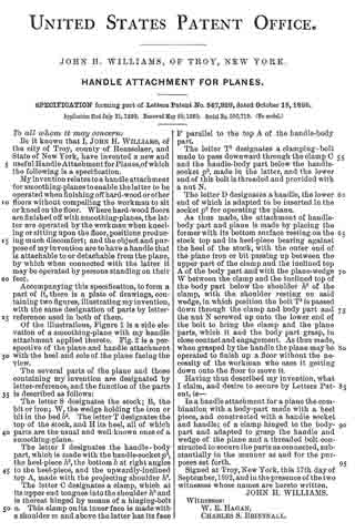
Of the illustrations, Figure 1 is a side elevation of a smoothing-plane with my handle attachment applied thereto. Fig. 2 is a perspective of the plane and handle attachment with the heel and sole of the plane facing the view.
The several parts of the plane and those containing my invention are designated by letter-reference, and the function of the parts is described as follows:
The letter S designates the stock; B, the bit or iron; W, the wedge holding the iron or bit in the bed b2. The letter T designates the top of the stock, and H its heel, all of which parts are the usual and well-known ones of a smoothing-plane.
The letter I designates the handle- body part, which is made with the handle-socket p2, the heel-piece h2, the bottom b at right angles to the heel-piece, and the upwardly-inclined top A, made with the projecting shoulder h3.
The letter C designates a clamp, which at its upper end tongues into the shoulder h3 and is thereat hinged by means of a hinging-bolt a. This clamp on its inner face is made with a shoulder m and above the latter has its face F parallel to the top A of the handle-body part.
The letter T2 designates a clamping-bolt made to pass downward through the clamp C and the handle-body part below the handle-socket p2, made in the latter, and the lower end of this bolt is threaded and provided with a nut N.
The letter D designates a handle, the lower end of which is adapted to be inserted in the socket p2 for operating the plane.
As thus made, the attachment of handle-body part and plane is made by placing the former with its bottom surface resting on the stock top and its heel-piece bearing against the heel of the stock, with the outer end of the plane iron or bit passing up between the upper part of the clamp and the inclined top A of the body part and with the plane-wedge W between the clamp and the inclined top of the body part below the shoulder h3 of the clamp, with the shoulder resting on said wedge, in which position the bolt T2 is passed down through the clamp and body part and the nut N screwed up onto the lower end of the bolt to bring the clamp and the plane parts, which it and the body part grasp, in close contact and engagement. As thus made, when grasped by the handle the plane may be operated to finish up a floor without the necessity of the workman who uses it getting down onto the floor to move it.
Having thus described my invention, what I claim, and desire to secure by Letters Patent, is —
In a handle attachment for a plane the combination with a body-part made with a heel piece, and constructed with a handle socket and handle; of a clamp hinged to the body-part and adapted to grasp the handle and wedge of the plane and a threaded bolt constructed to secure the parts as connected, substantially in the manner as and for the purposes set forth.
Signed at Troy, New York, this 17th day of September,1892, and in the presence of the two witnesses whose names are hereto written.
JOHN H. WILLIAMS.
Witnesses:
W. E. HAGAN,
CHARLES S. BRINTNALL.