No. 1,325,101 – Carriage-Maker’s Plane (Thomas A. Masters) (1919)
[paiddownloads id=”723″]1325101


UNITED STATES PATENT OFFICE.

_________________

THOMAS A. MASTERS, OF BINGHAM CANYON, UTAH.

CARRIAGE-MAKER’S PLANE.

_________________

1,325,101. Specification of Letters Patent. Patented Dec. 16, 1919.
Application filed April 3, 1919. Serial No. 287,291.

_________________

To all whom it may concern:

Be it known that I, THOMAS A. MASTERS, a citizen of the United States, residing at Bingham Canyon, in the county of Salt Lake and State of Utah, have invented certain new and useful Improvements in Carriage-Makers’ Planes, of which the following is a specification.

My invention relates to planes, and has particular reference to improvements in a carriage maker’s rabbet plane.

An important object of the invention is to provide means for preventing the shavings from sticking within the mouth of the plane, and clogging the same, such means being adapted to either raise the shavings and facilitate their discharge from the machine or cut or break the shavings thereby rendering them easy to discharge.

A further object of the invention is to provide a device of the above-mentioned character, which is simple in construction, cheap to manufacture and convenient to use.

Other objects and advantages of the invention will be apparent during the course of the following description.

In the accompanying drawings forming a part of this specification and in which like numerals are employed to designate like parts throughout the same;

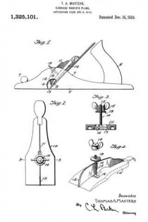
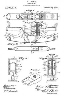
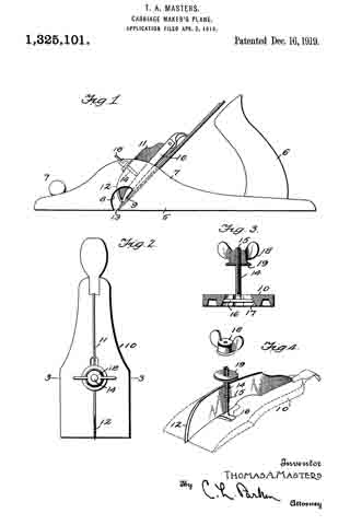
Figure 1 is a side elevation of a plane having my device applied thereto;

Fig. 2 is a side elevation of the clamping plate, having my attachment applied thereto;

Fig. 3 is a transverse sectional view, taken on line 3–3 of Fig. 2; and Fig. a is a perspective view of the attachment embodying my invention, parts being separated.

In the drawings, wherein for the purpose of illustration is shown a preferred embodiment of my invention, the numeral 5 designates the stock or body portion of a carriage maker’s rabbet plane, having the usual handle 6, secured to the rear end thereof, and knob 7 to the forward end. The stock 5 includes upstanding sides or flanges 7. Formed through the stock 5 is a transverse mouth 8, extending through the lower edge of the stock and through the opposite sides thereof. The numeral 9 designates the cutter blade of the plane, which extends for substantially the entire width of the stock 5 and mouth 8, thereby causing the shavings to stick within the mouth clogging the plane. The numeral 10 designates the usual clamping or adjusting plate carried by the stock 7 for locking the blade 9 in adjustment at the desired position.

My attachment comprises a blade 11, arranged upon edge and contacting with the plate 10. The blade 11 extends longitudinally of the plate 10 and has its lower end tapered, the same being provided with a rounded cutting edge 12. The lower end of the plate 10 projects into the mouth 8 and is positioned near the cutting edge 13 of the blade 9. The blade 11 is held in place by means of a bolt 14, having a longitudinal slot 15 receiving the blade 11. At its inner end the bolt 14 has a transverse head 16, held within a recess 17 formed upon the lower side of the plate 10. The upper end of the bolt 14 is screw threaded to receive a winged nut 18, contacting with a washer 19 arranged to engage the blade 11. By this means the blade 11 may be securely locked in place in clamping engagement with the plate 10.

The plane is used in the ordinary manner, and the shavings pass into the mouth 8, contact with the blade 11, and may be raised, thereby facilitating their discharge from the plane. The shavings which are not thus raised are split or broken up by the blade 11, whereby they freely discharge from the plane.

It is to be understood that the form of my invention herewith shown and described is to be taken as the preferred example of the same, and that various changes in the shape, size, and arrangement of parts may be resorted to without departing from the spirit of my invention or the scope of the subjoined claims.

Having thus described my invention, I claim :–

1. The combination with a bench plane, of a thin blade arranged transversely to and intermediate the width of the plane-bit and having its forward end sloping upwardly and rearwardly from the plane of said bit to raise or deflect the chips, and means for detachably mounting said blade.

2. The combination with a bench plane-bit, a thin blade arranged transversely and intermediate the width of the plane-bit, and having its forward edge sharpened to split the chip, and means for detachably mounting said blade.

3. The combination with the bench plane bit, of a thin blade arranged traversely of and intermediate the width of said bit, and having its forward edge sloped upwardly and rearwardly from the front of said bit, and sharpened to raise or deflect and split the chip and means for detachably securing the blade to the said bit.

In testimony whereof I affix my signature in presence of two wltnesses.

THOMAS A. MASTERS.

Witnesses:
J. L. HUCHEL, D. D. S.,
JESS. ZABRISPIE.

No. 1,182,719 – Rabbet-Plane (John F. Thunell) (1916)

[paiddownloads id=”712″]1182719


UNITED STATES PATENT OFFICE.
_________________

JOHN F. THUNELL, OF SALT LAKE CITY, UTAH.
RABBET-PLANE.

_________________

1,182,719. Specification of Letters Patent. Patented May. 9, 1916.
Application filed November 2, 1915. Serial No. 59,178.

_________________

To all whom it may concern:

Be it known that I, JOHN F. THUNELL, a citizen of the United States, residing at Salt Lake City, in the county of Salt Lake and State of Utah, have invented certain new and useful Improvements in Rabbet-Planes, of which the following is a specification.

This invention relates to hand planes, and pertains especially to planes for cutting curved or circular rabbets of various forms and curvature, and having adjustable runners.

The object of the invention is to provide novel and peculiar means for adjusting a pair of plane runners equally and without variation between the runners in perfecting their uniform adjustment.

A further object of the invention is to provide mechanism connecting the free end of the runners of a rabbet plane and fulcrumed within the plane body whereby the runners may be given uniform adjustment, and to furnish novel and peculiar means for operating said mechanism to give the runners such uniform curvature as desired or as occasion may demand, without separate adjustment of the runners.

Various other objects, advantages and improved results are attainable in the practical application of the invention as hereinafter fully described.

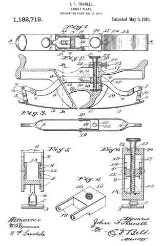
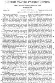
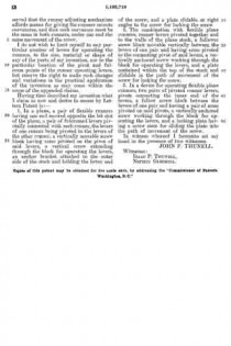
In the accompanying drawings forming part of this application :– Figure 1 is a top view of a rabbet plane embodying my invention. Fig. 2 is a sectional view taken on the plane indicated by the dotted line A–A Fig. 1, with the bit adjusting device removed. Fig. 3 is a detail plan view of the runner operating levers and follower block. Fig. 4 is a detail perspective view of the screw-locking device. Fig. 5 is an enlarged sectional view taken on the dotted line B–B Fig. 2. Fig. 6 is a similar view taken on the dotted line C–C Fig. 2.

The same reference characters denote the same parts throughout the several views of the drawings.

The means operated by the screw 1, for adjusting the bit 2, is covered by my application Ser. No. 872,608, allowed July 12, 1915, and therefore the same is not claimed in this application, and while the runners of this application are the same as those shown in said allowed application, the mechanism for operating the flexible runners 3, and the device for locking said mechanism to fix the runners in various positions constitute the subject of this application.

The runner operating mechanism comprises a pair of duplicate levers 4, pivotally connected at 5 with the movable end of the runners 3, by a forked hanger 6, pivoted at 7, to the outer end of the levers 4 where they are united in pairs. The levers 4 are branched laterally in pairs from their outer end and extend through the inclined throat wall 3 and adjacent to the side walls 9 of the throat. The pair of levers for one runner are pivoted to the pair of levers for the other runner by pivot pins 10, and the levers of one pair are pivoted at 11, to the throat walls 9, while the levers of the other pair are fulcrumed to and between the walls 9 and a vertical wall 12. One pair of the levers are operated through slots 13, in the wall 8, and the other pair of levers are operated through slots 14, in the wall 12. The device for operating the levers comprises a follower block 15 having a screw threaded aperture 16, for a screw 17, and a pair of arms 13 fulcrumed to the lever 4 by means of the lever pins 10. The screw 17 is anchored by means of a bracket 19 secured to and projecting inwardly from the wall 12, and said screw projects through a top wall 20 of the plane and is provided with a milled head for turning the screw in the anchor bracket, whereby the follower block 15 is moved vertically, and by such movement operates the levers 4 which carry the runners 3 to various curved positions as desired or as occasion may demand. The device for locking the screw and thereby fixing the levers and the runners in desired position for operating the plane, comprises a plate 21 slidably contained within the wall 20, and having an aperture 22 for the screw 17, and a screw stem 23 provided with a thumb nut 24 working against the outer face of the wall 20 for sliding the plate into and out of engagement with the screw. Obviously when the screw is locked the levers 4 and the runners are fixed in position for operating the plane.

It will be seen that the movement of the levers and runners is not only accomplished by operating the screw 17, but the screw and its locking device controls the levers and the runners so that the set position of the runners may be maintained during a planing operation. It will be further observed that the runner adjusting mechanism affords means for giving the runners minute curvatures, and that such curvature must be the same in both runners, under one and the same movement of the screw.

I do not wish to limit myself to any particular number of levers for operating the runners, to the size, material or shape of any of the parts of my invention, nor to the particular location of the pivot and fulcrum points of the runner operating levers, but reserve the right to make such changes and variations in the practical application of the invention as may come within the scope of the appended claims.

Having thus described my invention what I claim as new and desire to secure by Letters Patent is:–

1. In a plane, a pair of flexible runners having one end secured opposite the bit slot of the plane, a pair of fulcrumed levers pivotally connected with each runner, the levers of one runner being pivoted to the levers of the other runner, a vertically movable screw block having arms pivoted on the pivot of said levers, a vertical screw extending through the block for operating the levers, an anchor bracket attached to the outer side of the stock and holding the lower end of the screw, and a plate slidable at right angles to the screw for locking the screw.

2. The combination with flexible plane runners, runner levers pivoted together and to the walls of the plane stock, a follower screw block movable vertically between the levers of one pair and having arms pivoted to the connecting pivot of said levers, a vertically anchored screw working through the block for operating the levers, and a plate contained within the top of the stock and slidable in the path of movement of the screw for locking the screw.

3. In a device for operating flexible plane runners, two pairs of pivoted runner levers, pivots connecting the inner end of the levers, a follow screw block between the levers of one pair and having a pairof arms pivoted on said pivots, a vertically anchored screw working through the block for operating the levers, and a locking plate having a screw stem for sliding the plate into the path of movement of the screw.

In witness whereof I hereunto set my hand in the presence of two witnesses.

JOHN F. THUNELL.

Witnesses:
ISAAC P. THUNELL,
NEPHIN GLEDHILL.

_________________

Copies of this patent may be obtained for five cents each, by addressing the “Commissioner of Patents, Washington, D. C.”
_________________

No. 1,171,076 – Hand-Plane (John F. Thunell) (1916)

[paiddownloads id=”709″]1171076


UNITED STATES PATENT OFFICE.

_________________

JOHN F. THUNELL, OF SALT LAKE CITY, UTAH.

HAND-PLANE.

_________________

1,171,076. Specification of Letters Patent. Patented Feb. 8, 1916.
Application filed November 17, 1914. Serial No. 872,608.

_________________

To all whom it may concern:

Be it known that I, JOHN F. THUNELL, a citizen of the United States, residing at Salt Lake City, in the county of Salt Lake and State of Utah, have invented certain new and useful improvements in Hand-Planes, of which the following is a specification.

This invention relates to bit adjustments for hand planes, and the object of the invention is to provide novel and peculiar means for adjusting hand plane bits which shall be of simple construction, conveniently assembled, and accurately manipulated.

The object of the invention is to provide novel and peculiar means for adjusting and fixing the plane bit, and special means for hanging and adjusting the base or surface bearing plates of the plane.

A further object of the invention is to provide in the bit adjustment, convenient, simple, durable and effective means for giving the bit minute, accurate and positive adjustment independent of the base plate adjustment.

A still further object of the invention is to provide a pair of surface or runner plates, and a screw rod hinged to each plate, and a pair of adjusting and locking nuts for each rod, the adjusting nuts being held within the plane stock.

Other objects, advantages and improved results will be found in the practical application of the plane.

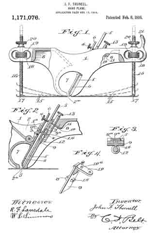
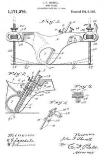
In the accompanying drawings forming part of this application: Figure 1 is a side elevation showing in dotted lines the various positions of the base plates. Fig. 2 is a sectional view of the bit device. Fig. 3 is a detail cross section on the dotted lines x–x, Fig. 2. Fig. 4 is a detail perspective view of the bit bracket.

The same reference characters denote the same parts throughout the several views of the drawings.

The plane stock or body 1, has a concavity 2 in its top in which set-screws 3 and 4 are operated in connection with a bit 5 and its keeper 6. The screw 3 works through a hinged carrier 1a, to connect the keeper therewith, and the thumb screw 4 works through the upper end of the keeper as usual. A transverse opening 7 is made through the stock under the ccncavity 2, and a bit slot 2a is made through the bottom wall of the opening 7. The under side of the stock is cut out at 8, for the purpose of reducing the weight of the plane, and for the purpose of housing the bit adjusting device. The bit adjusting device comprises a bracket the long plate 9 of which has a lug 8a working in the bit slots 9a covered by the plate 9, and the short plate 10 of the bracket is secured to the inclined wall 11 of the cut out portion 8 of the stock. The plate 10 forms a collar 10a in which a worm screw 12 is operated. Said screw having a stem extending through the top of the stock on an incline and parallel with the bit, and the stem is provided with a thumb head 13 for operating the screw. The plate 9 is provided with a follower projection 14 meshing with the screw 12, and the plate 9 has a forked end for the plate 10.

The pair of flexible runners 15, have their inner ends secured flush with the bit slot 2a, and the outer end of each plate is curved upwardly. A screw rod 16 is hinged or pivoted at 17 adjacent to the said curved end of each plate, and said rods extend through the ends of the stock 1. The ends of the stock are provided with transverse slots 18 and hold thumb nuts 19 for operating the rods 16, and set nuts 20 are provided for holding the rods in set position. One end of the stock is provided with a hand abutment 21 projecting above the nut 20 at this end of the stock, and thereby prevents the hand from interfering with the nut and rod.

It will be observed that the follower answers two purposes, it forms the connection between the bit and the bracket, and it also affords means for imparting to the bit the movement of the worm screw.

Having thus described my invention what I claim as new and desire to secure by Letters Patent is :–

In a bit plane, a plane throat the under wall of which has a slot lengthwise thereof, a plate of larger area than the slot and slidable on the under face of said wall opposite the slot, a lug on the upper face of the plate and projecting through the slot into engagement with the bit, a lug on the lower face of the plate, and a screw spaced apart from said wall equal to the thickness of the plate and engaging the plate and the lower lug to keep the upper lug in engagement with the bit for longitudinal adjustment by the screw.

In witness whereof I hereunto set my hand in the presence of two witnesses.

JOHN F. THUNELL.

Witnesses:
ISAAC P. THUNELL,
MATIE S. ASHTON.

_________________

Copies of this patent may be obtained for five cents each, by addressing the “Commissioner of Patents, Washington, D. C.”
_________________

No. 817,096 – Adjustable Plane-Handle (Fred Allen Shontz) (1906)

[paiddownloads id=”629″]817096


UNITED STATES PATENT OFFICE.

_________________

FRED ALLEN SHONTZ, OF EUREKA, UTAH.

ADJUSTABLE PLANE-HANDLE.

_________________

817,096. Specification of Letters Patent. Patented April 3, 1906.
Application filed February 27, 1905. Serial No. 247,525.

_________________

To all whom it may concern:

Be it known that I, FRED ALLEN SHONTZ, a citizen of the United States, residing at Eureka, in the county of Juab and State of Utah, have invented a new and useful lmprovement in Adjustable Plane-Handles, of which the following is a specification.

This invention is an improvement on the adjustable plane-handle for which I have filed application of Letters Patent under date of July 27, 1904, Serial No. 218,420.

The object of these improvements is to strengthen the construction and otherwise perfect the various details of construction.

This invention consists in a sleeve threaded adjacent its upper end, said sleeve extending through the plane-handle, a plate adapted to rock laterally on the plane-base and to receive the lower end of the sleeve, and a plunger-rod working through the said sleeve and curved adjacent its lower end.

The invention also consists in the novel features of construction and combination of parts hereinafter described, pointed out in the claims, and shown in the accompanying drawings, in which —

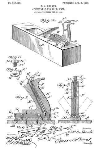
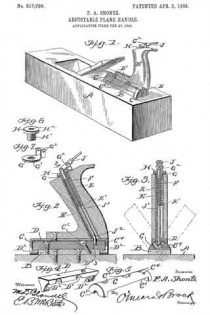
Figure 1 is a perspective view showing the application of my handle to a plane. Fig. 2 is a detail vertical sectional view through the handle. Fig. 3 is a section on the line 3 3 of Fig. 2. Fig. 4 is a detail perspective view of a rocker-plate. Fig. 5 is a detail perspective view of a block adapted to support the rocker-plate. Figs. 6 and 7 are detail perspective views of a tubular nut and a washer-plate, respectively.

In the drawings, A represents a plane of any make or construction having on its upper face a boss B. A block C, semicylindrical in cross-section, is cut out on its under straight face, as shown at C’, to fit over the boss B. The block is apertured at C2 for the reception of countersunk screws and at the ends is notched, as shown at C3. Radially-arranged apertures are formed therein, as shown at C3, said apertures or bores being parallel to the ends of the block. A rocker-plate D has a flat smooth upper face and is curved on its under face to fit the curvature of the block C, as shown in Fig. 3, and the plate has also depending end portions which carry inwardly-extending pintles D2, adapted to engage the notches C3 of the block C. The plate is recessed on one longitudinal edge, said recesses being adapted to aline with the apertures C2 of the block C, whereby access is had to the screw-heads for the purpose of tightening or removing the screws connecting the block C to the boss B. The plate D is also apertured at D3 to receive the lower end of a sleeve F, hereinafter described, the aperture D3 being placed so that it can be brought successively in alinement with the bores C4 as the plate is rocked on the block C. The handle E is mounted on the plate D, to which it is secured by a suitable screw and placed longitudinally in the handle, and downwardly and rearwardly inclined is a metal sleeve F, threaded internally adjacent its upper end and having its lower end in engagement with the aperture D3 of the plate D, the said lower end extending below the handle E and into aperture D. On the upper end of the handle is placed a washer or plate G, having a circular opening G’ in alinement with the upper open end of the sleeve F and carrying on one side two parallel upward arms G2, between which a lever J is pivoted intermediate its ends.

A tubular nut having a head H, threaded shank portion H’, and bore H2 serves to lock the washer or plate G to the handle, and a plunger-rod J’, which works in the sleeve F, projects through the bore H2 of the nut and is pivotally connected at its upper end to the lever J. Adjacent its lower end the plunger is bent or curved, as shown at J2, and this bent portion engages the apertures or bores C4 of the block C, working through the aperture D3 of the plate D. A coil-spring K is placed in the sleeve F around the plunger-rod J’ and bears at its upper end against the inner end of the tubular nut and at its lower end on a stop-pin K’, carried by the plunger-rod J’.

By means of the above construction a very substantial handle is formed which can be adjusted laterally with respect to the plane and locked by the plunger-rod J’ in its adjusted position.

Having thus fully described my invention, what I claim as new, and desire to secure by Letters Patent, is —

1. A device of the kind described oornprising a semicylindrical block having a plurality of radial bores therein, a rocker-plate pivotally connected to each end of the block and adapted to rock laterally thereon, said plate having an aperture adapted to aline with the bores of the block, a plane-handle carried by the plate, a sleeve having its inner end in engagement with the aperture of the plate, a plunger-rod working in the sleeve, and means for operating the plunger-rod.

2. The combination with a plane, of a semicylindrical block carried thereon and having radial bores parallel to the ends of the block, a plate curved on its under face and having inwardly-extending pintles at its ends, the block having notches at the ends to receive the said pintles, the said plate having an aperture adapted to aline with the bores of the block, a handle carried by the plate, a sleeve downwardly and rearwardy inclined and carried by the handle, the lower end of said sleeve engaging the aperture of the plate, and a plunger-rod working in the sleeve and curved adjacent its lower end, the said lower portion of the rod working through the aperture of the plate and engaging one of the said bores of the block.

3. The combination with a plane, a block semicylindrical in cross-section carried by the plane, and having apertures adapted to receive screw-heads and notched at the ends, the said block having a plurality of radial bores, a plate flat on its upper face and curved on its lower face, and having downwardly-extending ends, pintles carried by the said ends adapted to engage the notches of the block, the said plate being recessed on one side edge, said recesses alining with the screw-receiving apertures of the block, and the plate being apertured in alinement with the radial bores of the block, a handle carried by the plate, and a plunger working through the handle and adapted to engage the bores of the block as and for the purpose set forth.

4. The combination with a plane, a block having radial bores, a plate having the pivot-pins at each end in engagement with the ends of the block and apertured in alinernent with the bores, a handle carried by the plate, an inclined sleeve passing longitudinally through the handle, a plate on the upper end of the handle apertured to aline with the upper end of the sleeve, vertical arms carried by the plate, a lever pivoted between said arms, a headed, tubular screw passing through the plate on the handle and into the sleeve, the aperture of the plate and the interior of the upper end portion of the sleeve being threaded, a plunger-rod curved adjacent its lower end and having its upper end portion projecting through the tubular nut and pivotally connected to the lever, a pin on the plunger, and a coil-spring in the sleeve between the pin and inner end of the nut, as and for the purpose set forth.

FRED ALLEN SHONTZ.

Witnesses:
D. B. CRONIN,
F. CHRISTIANSON.

No. 790,533 – Adjustable Plane-Handle (Fred Allen Shontz) (1905)

[paiddownloads id=”621″]790533


UNITED STATES PATENT OFFICE.

_________________

FRED ALLEN SHONTZ, OF EUREKA, UTAH.

ADJUSTABLE PLANE-HANDLE.

_________________

SPECIFICATION forming part of Letters Patent No. 790,533, dated May 23, 1905.
Application filed July 27, 1904. Serial No. 218,420.

_________________

To all whom it may concern:

Be it known that I, FRED ALLEN SHONTZ, a citizen of the United States, residing at Eureka, in the county of Juab and State of Utah, have invented a new and useful Improvement in Adjustable Plane-Handles, of which the following is a specification.

This invention is an adjustable handle for planes, and while capable of use in connection with any construction of plane is preferably employed in connection with the rabbet-plane having a metal base.

The object of the invention is to provide a plane having a laterally-adjustable handle, so that the said plane can be conveniently used in positions where it would be inconvenient to use a plane with a non-adjustable handle, owing to the hand of the operator coming in contact with the work being operated upon.

The invention consists in the novel features of construction and combination of parts hereinafter fully described, and pointed out in the claims.

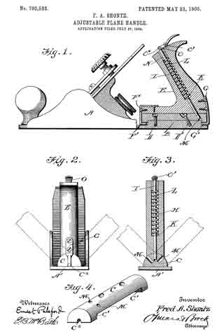
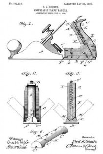
In the drawings forming a part of this specification, Figure 1 is a sectional elevation illustrating my invention. Fig. 2 is an end view of the plane provided with my improved form of handle, the dotted lines showing the different adjustments of the handle. Fig. 3 is a sectional view taken through the handle. Fig. 4 is a detail perspective view of the block to which the handle is connected.

In carrying out my invention I employ a plane A, the base A’ of which is provided with an essentially rectangular-shaped boss B, to which is secured a block C, essentially semi-circular in cross-section, the bottom face of said block being cut away intermediate the ends, as shown at C’, in order to fit snugly upon the boss B. Screws D and D’ are employed for securely connecting the block C to the boss B on the base of the plane. E indicates the handle, which is shaped substantially the same as the ordinary handle, said handle being connected to the block C by means of brackets F and G, having journal or pivot portions F’ and G’, which engage the bearing-recesses C2, formed in the lower face of the end portions of the block C. The handle E has a bore H extending from the upper to the lower end thereof, the upper portion of said bore being of greater diameter than the lower portion, and working in said bore is the locking-rod I, having a pin K passed transversely therethrough, and bearing upon said pin is a spiral spring L, the normal tendency of which is to project the lower end of the rod through the handle and into engagement with one of a series of oblique openings M, formed radially in the periphery of the block C, thereby locking the handle in either a central or a right or left position. The upper end of the spring L engages the tubular plug N, fitted in the upper end of the bore H, and a thumb-lever O is pivoted at O’ to the top of the handle E and is pivotally connected at O2 to the upper end of the rod I, and by pressing downwardly upon said thumb-lever the said rod is drawn up into the handle, so as to disengage its lower end from the opening M, and the handle can then be adjusted to the desired position and the rod will be thrown into engagement with the block by means of the spring L. It will thus be seen that I provide an adjustable handle and means for connecting the same to the base or stock of the plane, and it will be noted that said handle and its attaching means are capable of use in connection with any of the ordinary construction of planes now in use.

Having thus fully described my invention, what I claim as new, and desire to secure by Letters Patent, is —

1. A plane having a block secured to its base, a handle having brackets connected to the opposite ends thereof, said brackets being pivotally connected to the ends of the block, said block having a series of openings arranged at different angles, a spring-actuated locking-rod arranged in the handle and adapted to engage the said openings and means for raising said locking-rod as set forth.

2. A plane, the base of which is provided with a boss, a block semicircular in cross-section, recessed upon its lower face, and secured to the boss, the opposite ends of said block having bearing-recesses, a handle having a bore extending therethrough, a spring-actuated rod arranged in said bore and provided with a thumb-lever for raising the said rod, block having a series of openings arranged upon different angles and adapted to be engaged by the lower end of the looking-rod, and brackets attached to the ends of the handle and provided with journals adapted to engage the bearing-recesses in the ends of the block as set forth.

FRED ALLEN SHONTZ.

Witnesses:
D. B. CRONIN,
F. CHRISTIANSON.

No. 781,771 – Plane (William H. Gardner, Jr.) (1905)

[paiddownloads id=”617″]781771


UNITED STATES PATENT OFFICE.

_________________

WIILLIAM H. GARDNER, JR., OF PARK CITY, UTAH.

PLANE.

_________________

SPECIFICATION forming part of Letters Patent No. 781,771, dated February 7, 1905.
Application filed April 21, 1904. Serial No. 204,268.

_________________

To all whom it may concern:

Be it known that I, WILLIAM H. GARDNER, Jr., a citizen of the United States, residing at Park City, in the county of Summit and State of Utah, have invented certain new and useful Improvements in Planes; and I do declare the following to be a full, clear, and exact description of the invention, such as will enable others skilled in the art to which it appertains to make end use the same.

This invention relates to improvements in planes, and particularly to the class of rabbeting-planes.

The object of the invention is to provide a plane of this character having means whereby the handle may be adjusted to one side to permit the plane to be used close up against a shoulder without danger of striking the knuckles of the operator.

Another object is to provide means whereby the plane is prevented from becoming clogged with shavings.

With this and other objects in view the invention consists of certain novel features of construction, combination, and arrangement of parts, as will be more fully described, and particularly pointed out in the appended claims.

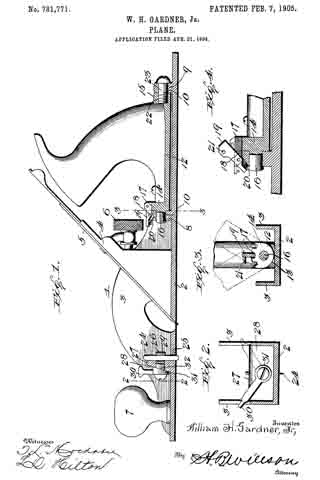
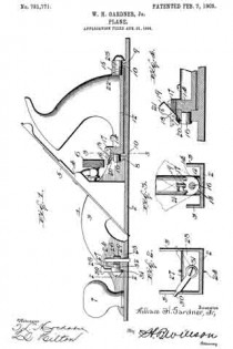
In the accompanying drawings, Figure 1 is a longitudinal vertical sectional view of a plane embodying the invention. Fig. 2 is a vertical cross-section on the line 2 2 of Fig. 1. Fig. 3 is a similar view on line 3 3 of Fig 1. Fig 4 is an enlarged fragmentary view of the plane-tree, the inner end of the handle-plate, and the device for locking the handle in its adjusted positions.

Referring more particularly to the drawings, 1 denotes a rabbeting-plane consisting of a bottom or base plate 2 and side flanges 3. Between said flanges is arranged the bit-support 4, on which is secured the plane-bit 5 and adjusting mechanism 6, by which said bit is regulated. These parts may be of the usual or any suitable construction.

On the forward end of the plate 2 is arranged the usual hand-knob or grip 7. On the rear end of the plate 2 is formed two upwardly-projecting lugs 8 and 9, in which are formed horizontal longitudinally-disposed apertures 10. Between the lugs 8 and 9 is arranged a narrow handle plate or bar 12, the lower side of which is curved or rounded in cross-section, as shown at 13. On the ends of the bar 12 are formed upwardly-projectingg ears or lugs 14 and 15. On the forward lug 14 is formed a forwardly-projecting stud or trunnion 16, which is adapted to pivotally engage the aperture 10 in the forward Iug 8, formed on the base-plate of the plane-tree.

On the upper edge of the lug 14 is formed a series of radial notches 17, preferably three in number, arranged as shown in Fig. 3 of the drawings. In the upper end of the lug 8 is formed a recess or slot 18, in which is pivotally mounted a pawl or dog 19, which is adapted to be engaged with one or the other of the notches 17 in the lug 14. A coiled spring 20 is mounted in a recess in the Iug 8 and is adapted to bear under the forward end of the pawl or dog 19 to hold the same in engagement with the notches 17. On the pawl or dog 19 is secured a laterally-projecting finger-piece 21, by which the pawl may be disengaged from said notches.

The lug 15 on the rear end of the plate or bar 12 is provided with a threaded aperture 22, into which is screwed the end of a pivot-screw 23, which passes through the apperture 10 of the lug 9, thereby pivoting this end of the handle to the plane-tree, thus permitting the handle to be swung laterally in either direction and locked in plaice. This radial or lateral adjustment of the handle permits the plane to be used close up against the shoulders formed by the rabbeting of a board without danger of injuring the knuckles of the operator.

It has been found in practice that planes of this character frequently choke up with shaings, due to the width of the shaving being sometimes greater than the width of the space between the side flages of the plane, so that the shaving binds and does not pass out. In order to overcome this difficulty I have devised a means for splitting the shavings, said means consisting of a vertically-disposed knife or cutter 24, the lower end of which is rounded end beveled to a thin sharp edge and is adapted to project through a slot 25, formed in the lower plate or base 2 of the plane-tree. ln order to adjustably hold the knife 24 in place in said slot, a clamping-bolt 26 is provided. Said bolt is mounted in a lug 27, which projects upwardly from the plate 2. The forward side of the lug has a beveled or cam face 28, while the rear face of the same is perpendicular or square. In the rear end of the bolt is formed a vertically-disposed slot 29, in which the knife 24 is disposed.

On the forward end of the bolt 26 between the head of the same and the beveled face 28 of the lug 27 is arranged a clamping-lever 30. On the inner end of said lever is formed a head 31, having a beveled or cam face 32, which is adapted to engage the beveled face 28 of the lug 27, so that when said lever is turned to the right the bolt 26 will be drawn forwardly, thereby clamping the blade of the knife tightly against the perpendicular side of the lug 27, in which position it will be firmly held until released by turning the lever 30 to the left. By this means the knife-blade may be adjusted to project its cutting end to the desired distance below the base-plate of the plane-tree and then clamped in this position, thus enabling slits of various depths to be cut. ln planing, the knife 24 is adjusted to project about the same distance as the plane-bit, so that a slit is formed in the wood in advance of the plane, thereby causing the shaving to split, which prevents the same from wedging in the throat of the plane.

While the primary object of the cutting blade or knife 24 is to split shavings, the same has been found useful for other purposes, such as for cutting veneers, leather, and other thin material in which a clean square edge is desirable.

From the foregoing description, taken in connection with the accompanying drawings, the construction and operation of the invention will be readily understood without requiring a more extended explanation.

Various changes in the form, proportion, and the minor details of construction may be resorted to without departing from the principle or sacrificing any of the advantages of this invention.

Having thus described my invention, what I claim as new, and desire to secure by Letters Patent, is —

l. ln a plane, the combination with the plane tree or stock, of a handle secured at its lower end to a plate or bar, apertured lugs or ears formed on the base-plate of said plane-tree, lugs formed on the ends of said handle plate or bar, a stud formed on the forward lug of said plate or bar and adapted to engage the aperture of the forward lug of said base-plate, a threaded aperture formed in the rear lug of said handle-plate to receive a pivot-bolt which is engaged with the aperture in the rear lug of said base-plate, whereby said handle-plate and handle is pivoted to said base-plate to swing laterally to one side or the other, and apawl for holding said handle in an upright or laterally-adusted position, substantially as described.

2. In a plane, the combination with the plane tree or stock, of a handle secured at its lower end to a plate or bar having a rounded under surface, apertured lugs or ears formed on the base-plate of said plane-tree, lugs on the ends of said handle plate or bar, a stud formed on the forward lug of said plate or bar, and adapted to engage the aperture of the forward lug of said base-plate, a threaded aperture formed in the rear lug of said handle-plate to receive a pivot-bolt which is engaged with the aperture in the rear lug of said base-plate, whereby said handle-plate and handle is pivoted to said base-plate to swing laterally to one side or the other, notches formed in the upper edge of the forward lug of said handle-plate and a spring-pawl pivotally connected to the adjacent lug of said plane-tree to engage one or the other of said notches and thereby hold said handle in an upright, or laterally-adjusted position, substantially as described.

In testimony whereof I have hereunto set my hand in presence of two subscribing witnesses.

WILLIAM H. GARDNER, JR.

Witnesses:
THOMAS GIBBONS,
H. G. BATES.

No. 538,937 – Combination-Plane (Jacob W. Tripp) (1895)

[paiddownloads id=”514″]538937


UNITED STATES PATENT OFFICE.

_________________

JACOB W. TRIPP, OF SALT LAKE CITY, UTAH TERRITORY.

COMBINATION-PLANE.

_________________

SPECIFICATION forming part of Letters Patent No. 538,937, dated May 7, 1895.
Application filed August 9, 1894. Serial No. 519,912. (No model.)

_________________

To all whom it may concern:

Be it known that I, JACOB W. TRIPP, of Salt Lake City, in the county of Salt Lake and Territory of Utah, have invented a new and Improved Combination-Plane, of which the following is a full, clear, and exact description.

The object of the invention is to provide a new and improved plane, which is comparatively simple and durable in construction, arranged for universal adjustment to enable the operator to conveniently plane straight or curved work, such as stair rails, on all sides, and for molding, fitting, plowing, tonguing and grooving, rabbeting and other purposes, also to form beads, fillets, &c.

The invention consists principally of a stock adapted to receive a removable wooden sole piece shaped to conform to the curved or straight surface to be planed.

The invention further consists in a bit having gear teeth adapted to be engaged by a segmental lever, for shifting the said bit into proper position.

The invention also consists in an auxiliary guide stock pivoted on an adjustable arm held on the main stock.

The invention also consists in certain parts and details, and combinations of the same, as will be fully described hereinafter, and then pointed out in the claims.

Reference is to be had to the accompanying drawings, forming a part of this specification, in which similar letters of reference indicate corresponding parts in all the views.

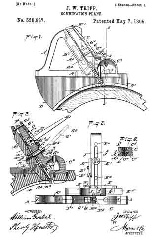
Figure 1 is a side elevation of the improvement. Fig. 2 is a plan view of the same. Fig. 3 is a sectional side elevation of the improvement on the line 3 3 of Fig. 2. Fig. 4 is an enlarged transverse section of the bit-guide, the section being taken on the line 4 4 of Fig. 3. Fig. 5 is a transverse section of the improvement on the line 5 5 of Fig. 1. Fig. 6 is a sectional rear elevation of part of the improvement on the line 6 6 of Fig. 5. Fig. 7 is a side elevation of the improvement, showing a modified form of sole-piece. Fig. 8 is a perspective view of a modified form of guide-piece for the auxiliary guide-stock. Fig. 9 is a perspective view of a modified form of sole-piece in front of the cutting-bit. Fig. 10 is a sectional plan view of part of the improvement on the line 10 10 of Fig. 7. Fig. 11 is a rear elevation of the auxiliary guide and adjacent parts. Fig. 12 is a side elevation of the improvement arranged with a straight wooden sole-piece, part of which is broken out. Fig. 13 is a sectional plan view of the same on the line 13 13 of Fig. 12. Fig. 14 is an inverted plan view of the bit. Fig. 15 is a plan view of the same. Fig. 16 is a face view of a combination quick cutter and blank. Fig. 17 is a face view of a modified form of fastening for the quick cutter, and Fig. 18 is a sectional plan view of the same on the line 18 18 of Fig. 17.

The improved plane is provided with the metallic stock A, having an integral handle A’, and a bit plate A2 extending in an inclined direction, as plainly shown in Figs. 1 and 3, and fastened by screws or other means to the stock A and handle A’. On the under side of the stock A, is adapted to be secured by screws orother means, a sole piece B, having its bottom made in various shapes according to the article to be planed. The sole piece is made of wood, and is shaped at its under side to correspond to the shape of the article to be planed, as will be readily understood by reference to Fig. 1, or is made straight at its under side for planing straight surfaces of different shapes, as illustrated in Fig. 12.

On the lower end of the cap C is secured a sole piece B’, forming a continuation of the sole piece B, and shaped according to the article under treatment, that is, either curved at the under side, as shown in Fig. 1, or straight as illustrated in Figs. 9 and 12. The pressure plate or cap C for the plane, is adapted to engage and hold the cutting bit D on the bit plate A2.

In order to shift the bit D, I form the top surface thereof at the upper end with rack teeth D’ adapted to be engaged by the teeth E’ of a segmental lever E, formed with a slot E2 adapted to engage a pin C’ extending transversely in the pressure plate C, and through an aperture C2 therein, as will be readily understood by reference to Fig. 3. Now when the pressure plate C is in place, the operator inserts the segmental lever E in the aperture C2, so that the pin C’ forms a fulcrum for the said lever, and the teeth E’ of the latter engage the rack teeth D’ of the bit D. When the operator swings the lever E either up or down, then the teeth E’ shift the bit D down or up, so as to adjust the cutting edge of the bit according to the under side of the sole piece B. After proper adjustment is made of the bit D, then the segmental lever E is again removed from the aperture C2 and the pin C’. The pressure plate or cap C is held from sliding by dowels F, F’, which project at right angles from the bit plate A2. See Fig. 3. To clamp the bit in place on the bit plate A2, I provide a screw rod F2, secured in the bit plate A2, parallel to the dowels F F’. The screw rod F2 is provided with the smooth piece F3, extending through the bit slot D2 and the cap C. The reduced end F4 of the screw rod F2 engages a removable block G, fitting under the head F5 of the said screw rod, and on the sides of the said block G is fulcrumed a cam lever G’, formed near its outer end with an opening G2 adapted to fit over the outer end of the dowel pin F’, whenever the said cam lever is in a closed position, as shown in Figs. 1, 3, and 12. The cam is formed on the fulcrumed end of the lever G’, and engages a wearing plate G4 held on the pressure plate C, so that when the lever G’ is swung inward, then the cam portion of the said lever presses on the wearing plate G4, to raise the block G, and to securely press the latter against the under side of the head F5 of the screw rod F2, whereby the pressure plate C is firmly pressed inward onto the bit D, to clamp the latter securely in position. The wearing plate G4 can be dispensed with in case the cap C is made of a hard material.

When the lever G’ is swung outward into the position shown in dotted lines in Fig. 3, then the cam end of the lever releases the block G from pressing on the head F5, thereby loosening the pressure plate C sufliciently to remove the cutting bit D as may be desired. In order to properly guide the bit D, I provide the under side thereof with a longitudinal recess D3, see Figs. 3 and 14, engaged by a lug A3 formed or secured on the bit plate A2.

On the lower end of the cap C, and abutting on the face of the bit D, is arranged an adjustable plate C4, formed with a longitudinally-extending shoulder C5 fitting into a correspondingly shaped groove in the cap or pressure plate C, as plainly shown in Fig. 4. A screw C6 serves to hold the adjustable plate C4 in place on the pressure plate C, the said screw passing through a longitudinally-extending slot C7 formed in the adjustable plate C4. By the arrangement described, the plate C4 can be readily adjusted on the pressure plate C, by loosening the screw C6, and then shifting the said adjustable plate C4 so that its lower end is as close down to the cutting edge of the bit as desirable, to permit of cutting in cross-grained wood without danger of tearing it or leaving a rough surface.

On the rear face of the stock A, is held adjustably a block H, provided with an obliquely-extending slot H’, through which passes a screw H2 screwing in the stock A, as teaser indicated in Figs. 6 and 7. A shoulder H4, see Fig. 10, formed on the back of this block H engages a correspondingly shaped groove A5 in the rear face of the bit plate A2, the said groove A5 being arranged parallel or in alignment with the slot H’, so as to permit of shifting the block H in an oblique direction on the stock, as required. On the back of the block H is formed a vertical recess or groove H3 (see Figs. 2 and 5), in which is held adjustable a quick cutter or bit I, for cutting the sides or edges of the wood under treatment, as plainly illustrated in Figs. 5 and 7. The quick cutter I, may be held in place on the block H, either by a screw I’, as shown in Fig. 5, or by making it dovetailed in cross section and clamping it in position at one edge by a cap H7 adapted to be fastened to the block H by a screw H8, as shown in Figs. 17 and 18. Instead of the cutter or bitI, I may place a blank I3 in the said groove H3, see Fig. 12, and the cutter I and blank I3 may be combined in a single piece, as illustrated in Fig. 16. The blank I3 is provided with a row of apertures, one of which is adapted to be engaged at a time by the set screw I’, but the blank may also be held in place by the cap H7 above mentioned. This blank I3, when used, prevents the shavings from accumulating in the plane throat and choking the plane, and is especially serviceable when cutting deep slots or grooves with the bit D, or other bits that may be used.

On the lower end of the block H is pivoted at J’, the auxiliary guide stock J, extending transversely, as plainly shown in the drawings, and carrying at its lower end an adjustable plate K, engaged by a set-screw K’ passing through a slot J2 extending longitudinally in the auxiliary guide-stock J. By this arrangement the plate K can be adjusted laterally in the guide stock according to the thickness or width of the wood under treatment. The screw K’ is adapted to engage one of a series of apertures K2, K3, K4, in the plate K, so as to increase the range of adjustment of the said plate K on the said guide-stock J.

On the front end of the plate K is arranged a foot-piece K5, made of wood or other suitable material, and shaped to correspond to the shape of the wood to be planed, as indicated in Figs. 5 and 8. The foot-piece K5 shown in Fig. 8 is more especially designed for use on twisted and crooked work. The foot-piece K5 is opposite the front sole-piece B’, secured to the under side of the shavings cup C9, as will be readily understood by reference to the dotted lines in Fig. 1, the said foot-piece also extending rearwardly a suitable distance, so that its rear end is about opposite the cutting edges of the bits D and I.

On one side of the auxiliary guide stock J is fitted to slide transversely, a block L, having a longitudinally extending groove L2 engaged by a set screw L’ screwing in the auxiliary guide-stock J, the screw L’ thus admitting of a right or left movement of the said block, and the screw is adapted to engage one of a series of tap apertures J3 in the auxiliary guide-stock J. See Fig. 11. A link N, pivotally connects this block L with a stud N’ secured on the block H, so that the upward and downward swinging motion of the auxiliary guide-stock is limited, but any desired adjustment can be made by adjusting the screw L’ in one of the series of tap apertures J3 in the auxiliary guide stock J. By this arrangement the auxiliary guide-stock J can be moved in a tilted position according to the wood under treatment, or the main stock A may be inclined, as shown in dotted lines in Fig. 5.

Now it will be seen that with the device described, almost any desired form of molding can be planed as the tool is universall adjustable for all kinds of work of any class desired.

Having thus described my invention, I claim as new and desire to secure by Letters Patent —

1. A plane having its body composed of two separable parts, to wit: a stock and a pressure-plate, in combination with a bit located between said parts, substantially as set forth.

2. The combination of a main stock having a bit-plate and a bit mounted thereon and provided with a series of rack teeth on its upper face, a pressure plate arranged over the bit and provided with a recess extending through it adjacent to the rack teeth of the bit, a rod extending transversely of said recess a lever with its bifurcations embracing said transverse rod and engaging the rack teeth in the bit, whereby the same may be adjusted, and means for locking said bit fast to the bit plate, substantially as set forth.

3. The combination of a main stock having a bit plate and a bit mounted thereon and provided with a series of rack teeth on its upper face, a pressure plate arranged over the bit and provided with a recess extending through it adjacent to the rack teeth of the bit, a rod extending transversely through said recess, a bifurcated lever adapted to be arranged in said recess with its bifurcations on opposite sides of said transverse rod and engaging the rack teeth in the bit, whereby the same may be adjusted, a screw rod connected at one end to the bit plate with its other end extending through the pressure plate, and a lever connected to the extremity of said screw rod and provided with a cam adapted to bear on said pressure plate, whereby the bit may be clamped in place, substantially as set forth.

4. A plane having its body composed of two separable parts to wit: a stock and a pressure plate, in combination with removable sole-pieces secured to said parts, substantially as set forth.

5. The combination of a main stock having a bit, a plate H adjustably connected to said stock and also provided with a bit, said plate H being adapted to be moved in a direction parallel to the direction in which the bit on the main stock moves, substantially as set forth.

6. The combination of a main stock having a bit, a plate H, adjustably connected to the said stock and adapted to be moved in a direction parallel to the direction in which the bit on the main stock moves, the bit I adjustably mounted on said plate H, and an adjustable lower portion for said plate H, adapted to form a lateral guide for the main stock, substantially as set forth.

7. The combination of a main stock having a bit, a plate H adjustably connected to the said stock and adapted to be moved in a direction parallel to the direction in which the bit on the main stock moves, a bit adjustably arranged between said plate H and the main stock, and a clamping device for said bit, substantially as set forth.

8. A plane having its body composed of two parts, to wit: — a stock and a pressure-plate, one part having projecting dowel pins and the other part having sockets to receive the dowel-pins, in combination with a bit located between said parts and provided with slots to receive said dowel pins, substantially as set forth.

9. A plane having its body composed of two parts, to wit: — a stock and a pressure-plate, one part having dowel pins and the other part having perforations for the passage of the dowel pins, in combination with a bit located between the two parts, and a clamping device mounted on the perforated part and adapted to clamp the two parts together, whereby said bit is held in place, substantially as set forth.

10. A plane having its body divided vertically into two parts, one part being a stock and the other part being a pressure-plate, dowel-pins projecting from one part, the other part being perforated for the passage of the dowel-pins, a bit located between the parts and having slots for the passage of the dowel-pins, and a clamping device mounted on the perforated part and engaging the dowel-pins of the other part, and adapted to clamp the bit in place between the two parts, substantially as set forth.

11. A plane having its body composed of two parts, to wit: a stock and a pressure-plate, each provided with a sole-piece, a bit located between the two parts, and a clamping device adapted to clamp said parts together, whereby the bit is held in place, substantially as set forth.

JACOB W. TRIPP.

Witnesses:
CHARLES G. CARTER,
C. H. STEBBINS.

No. 518,521 – Carpenter’s Plane (William E. Crompton) (1894)

[paiddownloads id=”506″]518521


UNITED STATES PATENT OFFICE.

_________________

WILLIAM E. CROMPTON, OF PARK CITY, UTAH TERRITORY.

CARPENTER’S PLANE.

_________________

SPECIFICATION forming part of Letters Patent No. 518,521, dated April 17, 1894.
Application filed July 14, 1893. Serial No. 480,526. (No model.)

_________________

To all whom it may concern:

Be it known that I, WILLIAM E. CROMPTON, a citizen of the United States, residing at Park City, in the county of Summit and Territory of Utah, have invented certain new and useful Improvements in Carpenters’ Planes; and I do hereby declare the following to beafull, clear, and exact description of the invention, such as will enable others skilled in the art to which it appertains to make and use the same.

My invention relates to improvements in planes, and especially to improvements in rabbet planes, and it consists of certain novel features hereinafter described and claimed.

The ordinary rabbet plane cuts a shaving somewhat wider than the plane, and this jams in the sides of the plane, rendering it necessary to stop to remove the same, and causing the inconvenience in working well known to persons skilled in the art. I have discovered that by splitting the shaving longitudinally, or rather by cutting a longitudinal slit in the wood before the shaving is pared oif by the bit, this inconvenience is almost entirely obviated.

My invention will be understood by reference tot he acccompanying drawings, in which the same parts are indicated by the same letters throughout the several views.

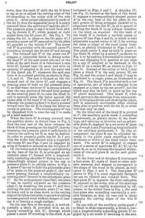
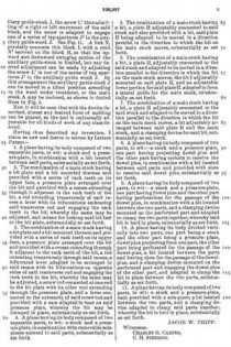
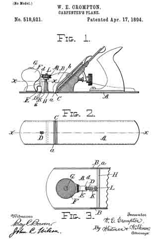
Figure 1 represents a longitudinal section of an ordinary form of rabbet plane along the line x’ x’ of Fig. 2, and illustrates the application of my improvement. Fig. 2 represents an inverted plan view of the plane shown in Fig. 1, and Fig. 3 represents an enlarged section along the line x x of Fig. 1, and looking down.

A represents the bottom plate or base of the plane provided with rear handle, sides B, bit C, and the other attachments commonly found in planes. The bottom plate A is slotted as at afor the passage therethrough of the bit C and of the shaving, and is also slotted at a’ to allow the passage of the knife D. The sides B are open as at b to allow the passage of the sides of the shaving.

The knife D is provided with a shoulder d resting on the tip of the spring E which is secured beneath the front handle F, and held in place by the screw G. This knife D is secured in a guide lug K, which lug is rigidly attached to the cross piece H between the sides B of the plane. A screw L is either set in or made integral with the said lug K, and on this screw the thumb wheel M is mounted, having a flange adapted to engage the upper end of the said knife D. It will be seen if the the said thumb wheel M be screwed down, that the knife D will be projected through the bottom of the plane, and that by means of the spring E, and the thumb wheel M, the knife D may be adjusted to the desired position.

The operation of the device is as follows: — The knife D and bit G being projected the required amount, which can only be determined by experiment, the plane is operated in the usual way. The knife D preceding the bit C, splits the surface of the wood in front of the said bit, and then these split parts readily slip or bend over one another, allowing the shaving to pass between the sides of the plane without jamming.

While this invention is particularly applicable to rabbet planes, it will be obvious that it may be used in connection with any of the planes ordinarily in use. In all of such planes, there is a tendency for the shaving to stick in the plane, and this is obviated by the device as already described.

Having thus described my invention, what I claim, and desire to secure by Letters Patent of the United States, is —

1. In a plane, the combination with a bit of a splitting knife D adjustably mounted in front of said bit, a spring E normally supporting said knife, a guide lug K inclosing the rear sides of said knife, a screw L attached to said lug, and a thumb wheel M adapted to bear on the upper part of said knife, substantially as and for the purposes described.

2. In a plane the combination with the bottom piece A slotted as at a and a’, the rear handle, the front handle F, and screw G, the bit C, the knife D, the spring E, the guide lug K, screw L and thumb wheel M, substantially as and for the purposes described.

In testimony whereof I affix my signature in presence of two witnesses.

WILLIAM E. CROMPTON.

Witnesses:
BISMARCK SNYDER,
WILSON I. SNYDER.

No. 516,780 – Plane (Jacob W. Tripp) (1894)

[paiddownloads id=”505″]516780


UNITED STATES PATENT OFFICE.

_________________

JACOB W. TRIPP, OF SALT LAKE CITY, UTAH TERRITORY.

PLANE.

_________________

SPECIFICATION forming part of Letters Patent No. 516,780, dated March 20, 1894.
Application filed June 12, 1893. Serial No. 477,337. (No model.)

_________________

To all whom it may concern:

Be it known that I, Jason W. TRIPP, a citizen of the United States, residing at Salt Lake City, in the county of Salt Lake and Territory of Utah, have invented certain new and useful Improvements in Planes, of which the following is a description, reference being had to the accompanying drawings, and to the letters of reference marked thereon.

My invention relates to planes, and more particularly to means for adjusting the bit.

It consists in the various matters hereinafter described and claimed, and is illustrated in the accompanying drawings, in which —

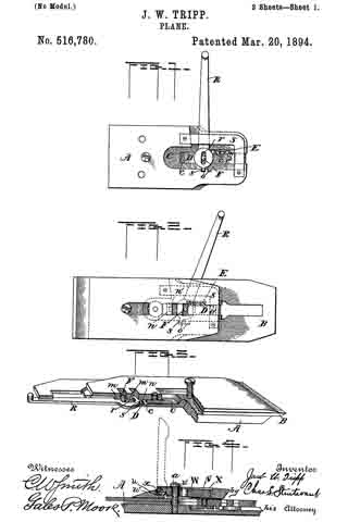
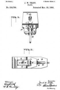
Figure 1 is a plan view of the bit plate illustrating more particularly the mechanism by which the bit is raised and lowered. Fig. 2 is a plan view with pressure cap removed showing lever mechanism in dotted lines. Fig. 3 is a perspective partly in section to show the means for adjusting the bit laterally. Fig. 4 is a detail of the pressure cap. Fig. 5 is a detail of the parts for adjusting the bit laterally; and Fig. 6 is a view of the top of the pressure cap.

In the drawings, A is a bit plate and B the bit. Hitherto it has been customary to provide a thumb screw or something similar thereto by which the bit is adjusted vertically, while the lateral adjustment has been effected by an additional member, in most cases a lever. I propose, however, to so construct the plane that one lever shall serve for both adjustments.

In order to provide a chamber for the necessary mechanism, I cut away a portion of the bit plate to form the part C and in the bottom of this I provide a groove c in which slides the block D, held in any position to which it may be brought by a suitable spring E. This spring may be of many constructions but I prefer to use that shown in the drawings, in which a spring plate is provided with projections e, which engage with teeth e’ on the side of the sliding block. A pin F projects from the sliding block and fits between the lugs m formed upon the bit cap so that when the block is moved it carries with it the bit, this being clamped to the bit cap in the usual manner. Another lug n provided with a recess n’ is formed upon the bit cap, while in the side of the bit plate, I provide one or more recesses o, these recesses being preferably dovetailed in order to more firmly hold the projection s for the purpose hereinafter set forth.

A lever R which projects above the rear portion of the bit when the plane is in position for use, is provided with a slot r fitting over the pin F, while upon its inner end is a projection s. A plate of metal S is fastened to the higher portion of the bit plate to prevent the lever from falling out of place when the bit is removed.

The operation of my device will be readily understood. Normally the projection s its in the recess n’ so that when the lever is moved to one side or the other, the pin F acting as a fulcrum, the edge of the bit will be correspondingly adjusted. To raise and lower the bit, the elongated slot r permits the lever to be drawn back until the projectionsis out of engagement with the recess n’, when the lever is turned to the right, the projection s is caught in one of the recesses o and as this projection then becomes a fulcrum, the sliding plate is moved by swinging the end of the lever. When the bit has been raised or lowered as desired, the lever is returned to its normal position.

While I prefer to employ the construction herein illustrated and described, it is manifest that many modifications may be made without in the least departing from the spirit of my invention.

It will be noticed that the lugs m, m and n, are so disposed that two slots for the reception of the pin F are provided instead of one, as found in planes of ordinary construction. The object of this is to adapt the bit for use with plane beds of different lengths.

Another feature of my invention is the pressure cap. At present, it is customary to provide caps with a hinged cam at their upper ends, these caps bearing upon the plane bit at two points only, viz., along the bottom of the pressure cap and at the point at which the cam touches the bit cap. The difficulty with this construction is that no pressure is exerted upon the main portion of the bit, and the result is that in planing hard wood, a slight spring is allowed that portion of the bit between the two bearing points of the pressure cap, thus permitting a slight vibration of the bit. In my device, however, I provide a plate u cut U-shaped as shown, and having its sides connected at the rear by a plate v of spring steel or other suitable material. To this plate v is attached a block W provided with an opening w for the plane bolt a projecting as usual from the bit plate, said block resting at its forward end upon the ledge u’ of the plate u. Hinged to the sides of the block is a yoke X having cams x adapted to bear upon the ledge u’. It will readily be seen that when the yoke of the pressure cap is raised, thus throwing the cams x up from the ledge u’, the cap may be slipped in position upon the plane, and upon the yoke being lowered, the plate u will be forced down upon the bit cap, its upper side resting against the head of the screw a as a fulcrum, bearing upon it with uniform force on the pressure cap’s entire under surface.

Having thus described my invention, what I claim as new, and desire to secure by Letters Patent, is —

1. A plane comprising a bit, a bit plate, a block sliding in said bit plate and connected to the bit, a lever connected to the sliding block, and means whereby said lever may be connected with either the bit or the bit plate; substantially as described.

2. A plane comprising a bit provided with a recess, a bit plate provided with a recess, a block sliding in said bit plate, and connected to the bit, and a lever-connected to the sliding block, said lever being adapted to engage either the bit recess or that formed in the bit plate; substantially as described.

3. A plane comprising a bit provided with a recess, a bit plate provided with a recess, a block sliding in said bit plate, a projection upon said block, a depression upon the bit adapted to receive the projection upon the block, a lever provided with a slot fitting over the projection upon the sliding block, and a projection upon said lever adapted to engage with either the bit recess or the recess formed in the bit plate; substantially as described.

4. A plane comprising a bit, a bit plate, ways in said bit plate, a block sliding in said ways and connected to the bit, a spring bearing against one edge of the block and the adjacent way, a lever connected to the sliding block, and means whereby said lever may be connected with either the bit or the bit plate; substantially as described.

5. A plane comprising a bit, a bit plate, ways in said bit plate, a recess formed in one of said ways, a spring plate in said recess, projections upon said spring plate, a block: sliding in said ways, teeth upon the side of the block adjacent to the spring in the way, a lever connected to the sliding block, and means whereby said lever maybe connected with either the bit or the bit plate; substantially as described.

6. A plane comprising a bit provided with a recess, a bit plate having a chamber C formed therein, a groove in said chamber, a block sliding in said groove, a projection upon said sliding block, a depression upon the bit and adapted to receive the projection upon the block, a recess in one wall of the chamber C, a lever provided with an elongated slot fitting upon the projection on the sliding block, a projection upon the lever adapted to engage either the bit recess or the recess formed in the bit plate, and a plate connecting the walls of the chamber; substantially as described.

7. A pressure cap for planes comprising a plate, an opening in said plate, a block hinged to said plate and provided with an opening for the insertion of the plane bolt, and means for raising the free end of the block against said plane bolt; substantially as described.

8. A pressure cap for planes comprising a U-shaped plate, a ledge connecting the lower portions of the sides of the plate, a spring plate connecting the upper ends of the sides of the plate, a block secured at one end to the spring plate and at the other resting upon the said ledge, an opening in said block for the passage of the plane bolt, a yoke hinged to the block at that end. which rests upon the ledge, and cams upon the yoke at its hinged end; substantially as described.

In testimony whereof I affix my signature in presence of two witnesses.

JACOB W. TRIPP.

Witnesses:
JOHN F. CORKER,
GERTRUDE E. CORKER.