No. 842,453 – Plane (Edwin W. Foster) (1907)
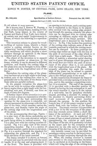
UNITED STATES PATENT OFFICE.
_________________
EDWIN W. FOSTER, OF CENTRAL PARK, LONG ISLAND, NEW YORK.
PLANE.
_________________
842,453. Specification of Letters Patent. Patented Jan. 29, 1907.
Application filed August 3, 1906. Serial No. 329,049.
_________________
To all whom it may concern:
Be it known that I, EDWIN W. FOSTER, a citizen of the United States, residing in Central Park, Long Island, in the county of Nassau and State of New York, have invented certain new and useful Improvements in Planes, of which the following is a specification.
This invention relates to planes for wood-working of various types, wherein a frame carries a cutting member known as the “plane-iron” having a cutting edge substantially rectilinear and which projects a short distance through an aperture in the frame member and at an angle thereto.
The object of the invention is to support the cutting member or plane-iron in the frame, whereby it can be secured in different positions, and thereby the cutting edge of the plane-iron can be brought to form different angles with the longitudinal axis of the frame.
Heretofore the cutting edge of the plane-iron has been set at a right angle to the longitudinal axis of the cutting-iron-that is, is perpendicular to the sides of the frame when these sides are parallel surfaces.
In the present invention the plane-iron can be set with its cutting edge making different angles than a right angle with the longitudinal axis and, if desired, can form an angle of forty-five degrees.
A further object of the invention is to provide in such a plane an organization whereby the portion of the base surrounding the opening for the plane-iron is rotatable, yet always maintains its alinement with the bottom of the form, which member carries the plane-iron, and thereby varies the angle of the cutting edge with the longitudinal axis of the plane.
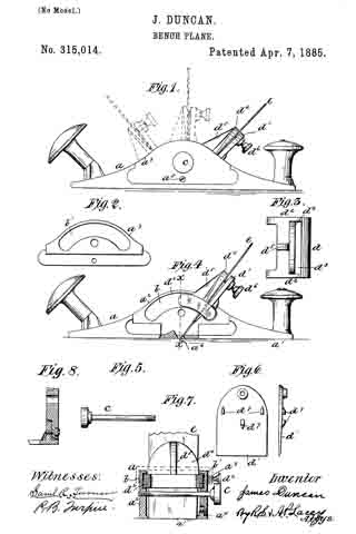
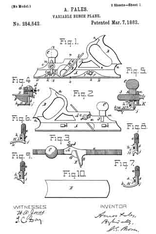
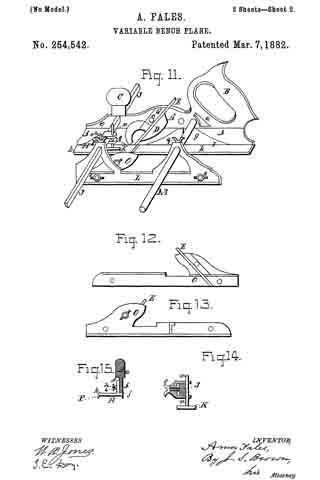
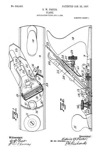
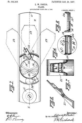
In the accompanying drawings, Figure 1 is a plan view of the device embodying my invention. Fig. 2 is a side elevation, certain parts being shown in vertical section. Fig. 3 is a plan view with the cutting member removed. Fig. 4 is a plan view of the rotary supporting member. Fig. 5 is a section of the latter member, partly shown in elevation. Fig. 6 is a section through the standard for supporting the plane-iron, and Fig. 7 is a front elevation of the latter member.
The frame member 9 is shown as formed of metal and may be provided with the usual handle 10 at the rear and gripping-knob 11 at the front. The frame is provided with an opening in its bottom, and a cutting member is supported in the frame to be adjustably secured with the cutting edge projecting through the opening, whereby the plane-iron can be clamped with its cutting edge extending at different angles with the longitudinal axis of the frame member. This longitudinal axis is denoted by the broken line x x. In Fig. 3 the broken-line positions of the cutting edge indicate some of the adjustable positions in which the cutting member can be clamped. In these positions the cutting edge makes an angle with the line of the path of movement of the edge which is other than a right angle. This will have the effect of making a somewhat spiral shaving and is of great advantage where the grain of the wood does not follow the path of movement of the plane — that is, is not parallel with the longitudinal axis of the plane. By properly adjusting this angle the cutting edge of the plane can be caused to operate substantially perpendicular or at right angles to the oblique grain of the wood.
In the construction illustrated the frame is provided with a circular opening 12 in its bottom, and in this opening a supporting member 13 is rotatable. The wall of the opening 12 is provided with a shoulder portion 14, formed by having its bore enlarged at 15, and the rotary member 13, that is in the nature of a turn-table, has its periphery similarly shaped, providing a shoulder 16, resting on the shoulder 14, thereby preventing downward movement of the rotary member through the opening. In this position the bottom face 17 ofthe rotary member is preferably flush with the bottom of the frame member. The rotary member 13 is provided with a slot 18 for the reception of the plane-iron that extends across within a short distance of the periphery. At each end of the slot 18 the member may be reinforced by means of lugs or raised portions 19 and 20 for strengthening the member at such parts. The edges of the slot 18 is preferably beveled at the upper part for the reception of the plane-iron on one side and to facilitate the escaping of the shaving on the other side.
Any suitable means may be provided for securing a cutting member to the rotary member with its edge projecting through the slot 18. When the cutting member is located and secured to the rotary member, the latter can be oscillated in its bearing in the frame, which will bring the edge of the cutting-iron to form different angles with the longitudinal axis x x of the plane. In all such positions the cutting member will enter the work at exactly the same depth — that is, will have the same adjustment — so that this rotary adjustment or swinging of the cutting-iron will not effect its cut and will not require further adjustment of the cutting member.
In the construction shown the rotary supporting member 13 has a standard or carrier 21 secured thereto in any suitable manner, as by screws 22, and extends upward, being inclined rearwardly at the usual angle formed by the plane-iron. The plane-iron 23 with its cap member 24 and clamp 25 are carried by the supporting member 21 and may be locked thereto in adjustable positions by the clamp-lever 26 in the usual manner. A usual form of screw-and-lever adjustment is shown, in which a lever 27, projecting into the iron at 23, is adjusted by a screw 29, that will vary the depth of out of the plane-iron.
Suitable clamping means are provided whereby the rotary supporting member 13 may be securely held in any position of adjustment. In the construction shown a screw-bolt 30 is carried by the frame member and engaged by a nut member 31, having an arm 32, by which it is swung. A clamping-plate 33 is placed between the screw and the frame and overhangs the edge of the rotary member 13. By turning the nut the latter plate will tightly engage the member 13 and force the shoulder portions of the member and frame together, locking them in adjusted positions.
If desired, another clamping member may be provided at the front portion of the plane comprising a screw 34, tapped into a threaded aperture 35 in the frame, the screw being operated by a mill-head 36. A clamping-plate 37 is engaged by the screw and presses the top of the rotary member 13, clamping the shoulder portions of the rotary member and frame together. When it is desired to vary the angle of the cutting edge, the screw members of the clamps are turned upward, releasing the rotary member 13. This member, with the plane-iron, is then swung to the desired position, either perpendicular to the axis of the plane or at any desired angle therewith. Thereupon the screw members of the clamp are tightened and the plane-iron is securely locked in such adjusted position.
Having thus described my invention, I claim —
1. In a plane, the combination of a frame member having a circular opening in its bottom containing the annular shoulder, a supporting member rotatable in said opening and having an annular shoulder engaging said shoulder whereby the lower face of the member will be substantially flush with the sole of the frame, the supporting member having a slot therein, a plane-iron carried by the supporting member and projecting into said slot, a clamping-plate arranged to engage the top of the frame and the supporting member at the rear of the frame, and a swinging lever on the frame and arranged to press the clamping-plate against the said portions of the frame and support to lock the support in adjusted positions.
2. In a plane, the combination of a frame member having a circular opening in its bottom containing the annular shoulder, a supporting member rotatable in said opening and having an annular shoulder engaging said shoulder whereby the lower face of the member will be substantially flush with the sole of the frame, the supporting member having a slot therein, a plane-iron carried by the supporting member and projecting into said slot, a clamping-plate arranged to engage the top of the frame and the supporting member at the rear of the frame, a swinging lever on the frame and arranged to press the clamping-plate against the said portions of the frame and support to lock the support in adjusted positions, and a clamping member engaging the top of the frame and of the supporting member at the front of the frame.
EDWIN W. FOSTER.
Witnesses:
WILLIAM H. REID,
JOHN O. SEIFERT.