No. 1,399,631 – Plane-Scraper (Charles J. Lofdahl And Carl A. Lofdahl) (1921)
[paiddownloads id=”730″]1399631


UNITED STATES PATENT OFFICE.

_________________

CHARLES J. LOFDAHL AND CARL A. LOFDAHL, OF JOLIET, ILLINOIS.

PLANE-SCRAPER.

_________________

1,399,631. Specification of Letters Patent. Patented Dec. 6, 1921.
Application filed December 27, 1919. Serial No. 347,754.

_________________

To all whom it may concern:

Be it known that we, CHARLES J. LOFDAHL and CARL A. LOFDAHL, citizens of the United States, residing at Joliet, in the county of Will and State of lllinois, have invented certain new and useful lrnprovenients in Plane-Scrapers, and we do hereby declare the following to be a full, clear, and exact description of the invention, such as will enable others skilled in the art to which it appertains to rnake and use the same.

This invention relates to certain new and useful improvements in a plane scraper and has for its primary object the provision of a device of this character which will be constructed in such rnanner that the blade may be readily adjusted at various angles and securely held in position.

Another object of the invention resides in the provision of a plane scraper of the above stated character which will be constructed so that the blade rnay be readily adusted to present a new edge when required, without the necessity of removing the blade and sharpening the same.

A further object of the invention resides in the provision of a wood scraper provided with an adjustable blade carriage in which the blade may be securely held against chattering thereby making it possible to obtain a much smoother dressed surface.

A further object of the invention resides in the provision of a wood working tool of the above stated character which may be readily employed by carpenters, cabinetmakers and other workmen and which will be light in weight, easy to operate and composed of the minimum number of parts.

With the foregoing and other objects in view as will appear as the description proceeds, the invention consists in the novel combination, arrangement and cooperation of parts as hereinafter more specifically set forth, claimed and shown in the drawings in which:

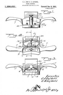
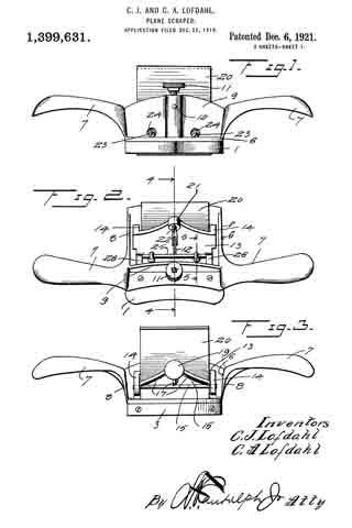
Figure 1 is a front elevation of the plane scraper.

Fig. 2 is a top plan view thereof.

Fig. 3 is a rear elevation.

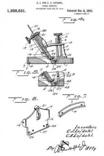
Fig. 4 is a verticle section on the plane of line 4–4 of Fig. 2.

Fig. 5 is a vertical section on the plane of line 5–5 of Fig. 2.

Fig. 6 is a detail perspective of the blade carriage removed, and

Fig. 7 is a detail perspective of the nose cap, removed.

Referring more in detail to the drawings, in which sirnilar reference characters designate corresponding parts throughout the several views, 1 designates the wood bottom having the blade opening 2 formed therein and a nose cap 3 secured upon its rear edge, said nose cap 3 being preferably forrned of metal and having an inturned lower flange 4 resting in the seat 5 formed therefor in the wood bottom, with the lower face of the flange 4 flush with the lower face of the wood bottorn 1, as will be clearly understood by reference to the drawings.

The metallic frame 6 is mounted upon the upper face of the wood bottom 1 and has a pair of oppositely extended curved hand grips 7 projecting from the opposite sides of the frarne 6, it being understood that the frame includes upwardly extended. side members 8 from vvhich the handles 7, extend at the forward corners of said members 6.
The frame also includes a front upstanding rnernber 9 with a central socket 10 formed on the outer face thereof and withln which is threaded a set screw 11, the lower end of which is adapted for binding engagement with the adjusting pin 12, which latter is pivoted to the front plate 13 of the blade carriage, said adjusting pin 12 having sliding movement through the front blade 9 and socket 10 in order that the blade carriage may be readily adjusted at any inclined angle desired.

The front plate 13 of the blade carriage has rearwardly extending ears 14 curved by its side portions and through which are extended the opposite ends of a locking rod 15 having binding engagement with the outer or rear face of the back plate 16 of the blade carriage, downward movement of the back plate 16 being limited by the flanges 17 formed on the diverging upper portions of the sides of said back plate 16 and which flanges also serve to reinforce or strengthen the back plate. This back plate 16 has a threaded ear 18 in its uppermost central portion and through which extends the shank of the set screw 19 for engagernent with the rear face of the blade 20 positioned between the front plate 13 and back plate 16 to assist in retaining the plate 20 in proper position within the carriage. The front plate 13 also has an uppermost central portion with a threaded ear 21 opposite the ear 18 of the back plate 15 with a bearing screw 22 adjustably positioned therein to engage the blade 20 at a point practically opposite the portion of the rear face of the blade 20 engaged by the set screw 19. The front plate 13 of the blade carriage also has a pair of lower bearing screws 23 adjustably mounted therein for proper bearing engagement with the front face of the blade 20 near the bottom of the blade carriage to cooperate with the bearing screw 22 when the three bearing screws are properly positioned to prevent chattering of the blade 20 during the use of the tool particularly when the tool is moving on its return stroke previous to another operative or cutting movement of the tool over the work. ln order that the lower bearing screws 23 may be readily adjusted when required, without the necessity of removing the tool carriage, the upstanding front member 9 is provided with a pair of spaced openings 24 opposite the heads of the screws, 23, for the using of a screw driver or other instrument required to readjust the screws 23.

In order that the carriage for the blade 20 may be readily adjusted in various inclined positions, the carriage is mounted upon a pivot rod or hinge rod 25 which passes through hinge ears 26 depending from the forward lower corners of the front plate 13 of the carriage and connected by the lower outwardly and upwardly curved lower edge of the front plate 13, which also serves to properly inclose the hinge rod 25 and protect the same from shavings which may become caught around the same. The turned lower edge of the plate 13 is indicated by the numeral 27. The ends of the hinge pin 25 are mounted in the downwardly extended portion 28 of the frame 6, in the forward portion of the blade opening 22 of the wood bottom 1 and which portion of the frame 6 extends through said opening 2 with a part thereof presenting a smooth lower face flush with the lower face of the bottom 1, thereby providing a blade and bottom protecting wearing strip 29 in the forward side of the blade opening 2.

It will be understood that the frame 6 and nose cap tl may be secured to the wood bottom 1 by screws or any other suitable means. lt will also be readily seen that by loosening the set screw 11, the blade carriage may be readily moved on the hinge pin 25 to adjust the incline of the blade and in order to raise or lower the blade in the carriage or remove the blade therefrom, it is simply necessary to loosen the set screw 19 in the back plate 16.

From the foregoing, taken in connection with the accompanying drawings, the complete operation of this plane scraper and the advantages of the novel features thereof will be readily apparent to those familiar with this art. Further detail description of the device is therefor believed to be unnecessary.

While the preferred embodiment of the invention has been illustrated and described, many minor changes in the details of construction and arrangement of parts may be resorted to within the scope of what is claimed without departing from the spirit of the invention.

What is claimed is :–

A frame, a rod spanning said frame, a front plate having a turned edge journaled on said rod, means associated with said plate and said frame to secure the plate in adjusted positions, ears extending from the plate, a rod mounted by said ears, a back plate intermediate said last rod and the adjacent portion of the front plate, flanges on the back plate resting on the second mentioned rod at one end, a blade intermediate the front plate and back plate of a width less than the width of the space between said plates, screws mounted by both of said plates and enagageable against the blade on opposite sides to vary the angularity thereof, and a screw on the front plate engageable with the blade to urge it against the back plate at a distance from the first mentioned screws.

In testimony whereof we affix our signatures in presence of two witnesses.

CHARLES J. LOFDAHL.
CARL A. LOFDAHL.

Witnesses:
JAMES G. SMITH,
NELS OLSON.

No. 1,098,706 – Hand-Scraper (Christian Bodmer) (1914)

[paiddownloads id=”696″]1098706


UNITED STATES PATENT OFFICE.

_________________

CHRISTIAN BODMER, OF NEW BRITAIN, CONNECTICUT, ASSIGNOR TO THE STANLEY RULE &
LEVEL COMPANY, OF NEW BRITAIN, CONNECTICUT, A CORPORATION OF CONNECTICUT.

HAND-SCRAPER.

_________________

1,098,706. Specification of Letters Patent. Patented June 2, 1914.
Application filed November 8, 1913. Serial No. 799,854.

_________________

To all whom it may concern:

Be it known that I, CHRISTIAN BODMER, a citizen of the United States, residing at New Britain, Hartford county, State of Connecticut, have invented certain new and useful Improvements in Hand-Scrapers, of which the following is a full, clear, and exact description.

My invention relates to an improvement in tools, and particularly to so-called hand scrapers such as employed for scraping or smoothing the surfaces of floors or other woodwork.

The invention relates more particularly to the body portion, which is constructed integrally of cast iron and is so designed as to properly hold the cutter in position for service.

It is the purpose of my invention to provide certain improvements in the construction of the body or frame, and by said improvements to overcome the errors and weaknesses existing in tools of this general description as heretofore constructed; that is to say, by the present design the user may grasp the tool in such a way as to apply his power with the greatest efficiency; the construction also being such that the handle portions are connected to the central body portion by a much stronger connection than that heretofore employed in an iron scraper body or frame.

In the accompanying is a perspective view scraper. Fig. 2 is a front elevation, partly in section. Fig. 3 is a rear elevation.

1 is the sole portion or base.

2 is an upwardly projecting wall arranged longitudinally of the base and between the front and rear edges.

3 is a slot which extends transversely through the base about midway betvveen the front and rear edges and just to the rear of the wall 2. The cutter, later described, projects through this slot, the slot being of an appropriate length for the cutter. The sole 1 and the wall 2 constitute the central portion of the scraper body or frame.

4–4 are handles which are arranged at each end of the central or main portion, the handles being cast integrally therewith, each handle being united to the central body portion in the unique manner now described. A description of the means for drawings, Figure 1 of my improved connecting one handle with the main body will suihce for both, as the means of connection corresponds in each instance.

5 is a curved flange connecting the inner end of the handle 4 with the side edge of the sole portion 1 forward of the wall 2.

6 is a curved flange connecting the inner end of the handle with the side edge of the sole portion 1 back of the wall 2.

7 is an upwardly curved flange connecting the handle with the side edge of the wall 2. These flanges operate in effect as longitudinally arranged strengthening ribs which extend far enough into the handle portion to constitute a very powerful connection. Each handle proper is in effect corrugated so as to get the maximum strength with the least weight, the corrugation being on the under side and appearing in Fig. 2 at the right hand side.

8 is a cutter blade.

9 is a clamping plate connected in any suitable manner, as by thumb screws 10–10 to the rear of the wall 2. This clamping plate 9 serves to hold the blade 8 firmly against the back of the wall 2, with the edge thereof projecting therethrough to the desired extent.

11 is a thumb screw which is located about midway in the wall 2 on the opposite side from the thumb screws 10–10. The inner end of this thumb screw 11 is arranged to engage the blade 8 to bend it slightly baclr at the center, as it is found that it operates more easily when thus buckled or bent.

In operation, the operator grasps the handles 4–4 with the fingers, while his thumbs project down into the spaces at the meeting angles of the front part of the sole, the front part of the wall and that part of the handle between the flanges 7 and 5. The ball of each thumb rests well down on the upper surface of the sole 1 very close to the work, so that the pressure of the thumbs will be applied to the greatest advantage, the position of the thumbs being such that a minimum of exertion is required of the operator, each thumb standing in a substantially straight position rather than being bent. Heretofore in the construction of iron scraper bodies it has been customary to provide a substantially vertical wall at each end of the sole 1, forming a box-like structure, thus requiring the operator to bend each thumb in order to get any thumb pressure directly on the sole. This is not only tiresome, but it is obvious that the operator’s full power cannot be applied when the pressure is exerted through the end of the thumb. It is apparent, of course that each handle curves upwardly so as to afford clearance for the fingers. In this, however, there is no novelty, as it is common in all scrapers of this general class.

In the old box-like type of construction above referred to, the connection between the handles and the main central body is comparatively weak, with the result that if the tool is accidentally dropped, breakage frequently occurs where one or the other handle is united to the main body. By the present invention I not only avoid the box-like structure due to the old end wall formation, but I also connect each handle with the main central body so that a maximum of strength is afforded, very much minimizing the danger of breakage. I have referred to that part of the main body which faces the operator as the front part. It will be understood that in operating the scraper the cutting stroke is performed ordinarily by pushing the tool away from the operator while pressing it firmly against the surface which is to be smoothed.

What I claim is:

1. A scraper body including a main central portion comprising a sole having a slot therein constituting a cutter opening, a wall projecting upwardly at the forward edge of said cutter opening, two handles arranged at opposite ends of the main central portion and integrally connected therewith, said connection including a series of longitudinally arranged rib-like flanges extending from the edges of the sole portion and said wall and merging by gentle curves into and forming part of the handles.

2. A scraper body including a main central portion comprising a sole having a slot therein constituting a cutter opening, a wall projecting upwardly at the forward edge of said cutter opening, two handles arranged at opposite ends of the main central portion and integrally connected therewith, said connection including a series of longitudinally arranged rib-like flanges extending from the edges of the sole portion and said wall and merging by gentle curves into and forming part of the handles, each handle being connected to the cutter opening by not less than three of said rib-like flanges, one of said flanges extending forwardly to meet the side edge of the sole forward of the wall, another extending rearwardly to meet the edge of the sole to the rear of the wall, another extending upwardly to meet the edge of said wall.

3. A scraper body including a main central portion comprising a sole having a slot therein constituting a cutter opening, a wall projecting upwardly at the forward edge of said cutter opening, two handles arranged at opposite ends of the main central portion and integrally connected therewith, said connection including a series of rib-like flanges extending longitudinally from the edges of the sole portion and said wall and merging by gentle curves into and forming part of the handles, with means for holding a cutter against the rear surface of said wall.

CHRISTIAN BODMER.

Wlitnesses :
JNO. BURDICK,
K. J. HOFFDIAN.

_________________

Copies of this patent may be obtained for five cents each, by addressing the “Commissioner of Patents, Washington, D. C.”
_________________

No. 917,568 – Scraper (Andrew Ekman) (1909)

[paiddownloads id=”660″]917568


UNITED STATES PATENT OFFICE.

_________________

ANDREW EKMAN, OF GRAND RAPIDS, MICHIGAN.

SCRAPER.

_________________

917,568. Specification of Letters Patent. Patented April 6, 1909.
Application filed June 22, 1908. Serial No. 439,883.

_________________

To all whom it may concern:

Be it known that I, ANDREW EKMAN, a citizen of the United States, residing at Grand Rapids, in the county of Kent and State of Michigan, have invented certain new and useful Improvements in Scrapers, of which the following is a specification.

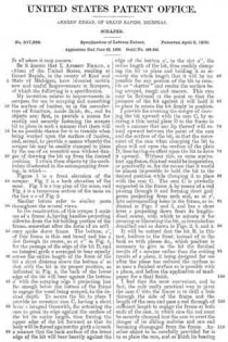
My invention relates to improvements in scrapers for use in scraping and smoothing the surface of lumber, as in the manufacture of furniture, inside finish, &c., and its objects are: first, to provide a means for readily and securely fastening the scraper bit to place in such a manner that there will be no possible chance for it to tremble when being worked upon the surface of lumber, and, second, to provide a means whereby the scraper bit may be readily clamped to place by the use of an eccentric cam without danger of draiving the bit up from the desired position. I attain these objects by the mechanism illustrated in the accompanying drawing, in which —

Figure 1 is a front elevation of the scraper. Fig. 2 is a back elevation of the same. Fig. 3 is a top plan of the same, and Fig. 4 is a transverse section of the same on the line x x of Fig. 2.

Similar letters refer to similar parts throughout the several views.

In the construction of this scraper I make use of a frame A, having handles projecting sidewise from the bit-holding portion of the frame, somewhat after the form of an ordinary spoke shave frame. The bottom, a’ of this frame is thin and broad and has a slot through its center, as at a” in Fig. 4, for the passage of the edge of the bit B, and an integral girth a arranged to bear equally across the entire length of the force of the bit a short distance above the bottom a’ so that with the bit in its proper position, as indicated in Fig. 4, the back of the lower edge of the bit will bear against the bottom a’ with the scraping edge b projecting just far enough below the bottom of the frame to engage the wood being scraped, to the desired depth. To secure the bit to place I provide an eccentric cam C, having a short lever c integral therewith, for actuating the cam to press its edge against the surface of the bit its entire length, thus forcing the upper edge of the bit forward so that its hotly will be forced against the girth a in such a manner that the back surface of the lower edge of the bit will bear heavily against the edge of the bottom a’, in the slot a”, the entire length of the bit, thus readily clamping the bit to place and holding it so securely the whole length that it will be impossible for any portion of the bit to tremble or “chatter” and render the surface being scraped, rough and uneven. This cam may be flattened at the point so that the pressure of the bit against it will hold it to place to retain the bit firmly in position.

I provide for averting the danger of drawing the bit upward with the cam C, by securing a thin metal plate D to the frame in such a manner that one lip thereof will extend upward between the point of the cam and the surface of the bit, so that the movement of the cam when clamping the bit to place will act upon the surface of the plate D, thus having no effect upon the bit to draw it upward. Without this, or some equivalent appliance, this tool would be inoperative, or practically so, for the reason that it would be almost impossible to hold the bit to the desired position while clamping it to place with the cam C. The cam C is pivotally supported in the frame A by means of a rod passing through it and forming short gudgeons projecting from each end, as at c’, into corresponding holes in the frame, as indicated in Figs. 2 and 3, and has a short lever c projecting down from its longitudinal center, with which to actuate it for securing or liberating the bit, as hereinbefore described and as shown in Figs. 2. 3, and 4.

It will be noticed that the bit B, in this tool, inclines to the front, instead of to the back as with planes &c., which position is bit the finished than the cutting designed for use necessary to give to the results of a scraper rather results of a plane, it being after the plane has reduced the surface to as near a finished surface as is possible with a plane, and before the application of sandpaper for a final finish.

I find that the most convenient, and in fact, the only really practical way to pivot the cam C into the frame is to drill a hole through the side of the frame and the length of the cam and pass a rod through of suflicient length to engage the frame at both ends of the cam, in which case the rod must be securely clamped into the cam to avert the danger of its sliding endwise and one end becoming disengaged from the frame. Another object to be carefully provided for is to so place the cam, and so finish its bearing edge, the bearing edge of the girth a and the bearing edge of the bottom plate a’ in the slot a” that the corresponding portions of the bit B will have perfect contact the entire length of the several bearing edges here mentioned. To release the bit B for removing it from the frame, it is only necessary to throw the handle c of the cam C up to the position indicated by the dotted lines in Fig. 4 when the plate D will be released and the bit may be readily removed or inserted.

What I claim as my invention, and desire to secure by Letters Patent, is:

In a furniture scraper, a supporting frame, a thin bottom thereto having a longitudinal slot through it, a girth connecting the sides of the trains above the bottom plate, in position so that a line from the bearing b on the bottom directly across the bearing face of the girth will incline sharply forwad, a bit extending up from the slot to and some distance above the girth, a protecting plate secured to the bottom of the frame and extending up along the surface of the bit, and a cam pivotally secured in the frame in position to bear against the protecting plate and force the bit solidly between the cam and the bearing b in the bottom of the frame on one side, and the girth on on the other side.

Signed at Grand Rapids Michigan June 19th, 1908.

ANDREW EKMAN.

In presence of —
T. M. NESBITT,
GEORGE L. KELNER.

No. 778,849 – Wood-Scraper (James R. Ellis) (1905)

[paiddownloads id=”611″]778849


UNITED STATES PATENT OFFICE.

_________________

JAMES R. ELLIS, OF CLEVELAND, OHIO.

WOOD-SCRAPER.

_________________

SPECIFICATION forming part of Letters Patent No. 778,849, dated January 3, 1905.
Application filed July 27, 1904. Serial No. 218,415.

_________________

To all whom it may concern:

Be it known that I, JAMES R. ELLIS, a citizen of the United States, residing at Cleveland, in the county of Cuyahoga and State of Ohio, have invented new and useful Improvements in Wood-Scrapers, of which the following is a specification.

This invention is an improved wood-scraper for the use of carpenters and cabinet-makers, and is characterized particularly by improvement with respect to the manner in which and the means by which the scraping-blade is held in the stock and also by other improved details of construction, as will be more fully apparent from the following description.

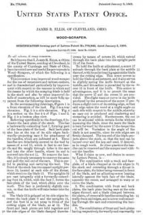
In the accompanying drawings, Figure 1 is a front elevation of the tool. Fig. 2 is a rear elevation. Fig. 3 is a side elevation. Fig. 4 is a section on the line 4 4 of Figs. 1 and 2. Fig. 5 is a bottom plan view.

Referring specifically to the drawings, 6 indicates the back plate of the stock. This has a backwardly-extending foot 7, forming part of the face-plate of the tool. Said back plate also has at the top of its side edges backwardly-projecting ears 8 for attachment of the handles, which are indicated at 9. These handles are detachably secured to the tool by means of a rod 10, which is fast to one handle and fits snugly through holes in the ears and into the other handle, where its end is screwed into the nut 11. To remove the handles, it is simply necessary to unscrew the same and pull the rod out of the ears. This is useful in packing and carrying the tool. The front of the stock has two spaced upright portions 12, located at each side of the throat, which receives the blade 13. The uprights 12 are cast integrally with a forwardly-extending foot 14, which, with the foot 7, forms the face-plate of the tool, which slides over the work. This face is preferably slightly convex, so that the knife will take better into the work.

The blade 13 is gripped at its side edges between the back plate 6 and the uprights 12, and the foot 14 is cut away in front of the cutting edges of the blade, as at 15. The front and back pieces are held together and the side edges of the blade clamped therebetween by means of screws 16, which extend through the back plate into the upright parts 12 of the front.

To hold the knife at adjustment, a screw 17 extends through the back plate at the middle thereof, with its point bearing against the blade near the cutting edge. This screw serves to hold the blade at adjustment, and it also serves to slightly spring the knife forward at the middle, and this action is permitted by the recess 15 in front of the knife. This action is advantageous, and it is to permit the same that the screw 17 and the recess 15 are provided. The slight warp or curve in the knife produced by the pressure of the screw 17 produces a slight curve of its cutting edge, so that said edge takes the wood at a slight angle on each side with respect to the middle, whereby an easy cut is produced and chattering and stuttering is avoided. Furthermore, the cut can be adjusted within certain limits without loosening the blade, since the more the blade is bent forward by the screw 17 the deeper the cut will be. Variation in the angle of the blade is not possible, since its side edges are firmly clamped. The top end of the blade projects above the stock, so that the tool can be turned over and the top end used, if desired, as in rough work. In close quarters the handles can be removed and the scraper used without the handles.

What I claim as new, and desire to secure by Letters Patent, is —

1. The combination with a stock and face-plate, of a blade clamped at its side edges in the stock and extending through a throat in the face-plate, the latter being recessed in front of the blade, and an adjusting-screw bearing laterally against the back face of the blade, opposite the recess, and arranged to warp or curve the blade.

2. The combination with front and back plates, the back plate having ears at the side edges thereof, and a blade clamped between the plates, of removable handles extending laterally from said edges, and a screw-rod extending through the ears and connecting the handles.

3. The combination of front and back plates having respectively forwardly and rearwardly extending feet forming a face-plate, a blade clamped at its side edges, only, between the plates, the front plate being recessed in front of the blade, and an adjusting-screw extending through the back plate and bearing against the blade, and arranged to warp or curve the blade.

In testimony whereof I have signed my name to this specification in the presence of two subscribing witnesses.

JAMES R. ELLIS.

Witnesses:
SHIRLEY BOMMHARDT,
JOHN A. BOMMHARDT.

No. 755,587 – Scraping-Plane (William Ulses) (1904)

[paiddownloads id=”600″]755587


UNITED STATES PATENT OFFICE.

_________________

WILLIAM ULSES, OF LOS ANGELES, CALIFORNIA.

SCRAPlNG-PLANE.

_________________

SPECIFICATION forming part of Letters Patent No. 744,587, dated March 22, 1904.
Application filed October 29, 1903. Serial No. 179,070. (No model.)

_________________

To all whom it may concern:

Be it known that I, WILLIAM ULSES, a citizen of the United States, residing at Los Angeles, in the county of Los Angeles and State of California, have invented new and useful Improvements in Scraping-Planes, of which the following is a specification.

My invention relates to a plane for finishing surfaces made nearly smooth by the ordinary cutting-planes; and the object thereof is to provide a tool by means of which planed surfaces may be readily finished and with less danger of roughing the surface than if an ordinary scraper were used.

I accomplish this object by the scraping-planes described herein and illustrated in the accompanying drawings, in which —

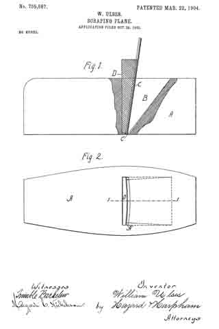
Figure 1 is a side elevation, with a portion in longitudinal central section taken on the line 1 1 of Fig. 2, of my scraping-plane. Fig. 2 is a view of the sole of my plane.

In the drawings, A is the stock, having a throat B for the reception of the plane-iron C and the binding-wedge D, which secures the plane-iron in the throat, binding it against abutments A’ on the sides of the throat. These abutments are shown in dotted lines in Fig. 1, the inner dotted line representing the top line of the abutments and the outer line representing the bottom line of the abutments. The tops of these abutments project forwardly of the bottoms, so that the top of the plane-iron is inclined forwardly, as shown in Fig. 1, when the wedge and iron are in place. I have found by practical test that an inclination of five-sixteenths of an inch in a stock of two inches in height produces very satisfactory results. The plane-iron is constructed, preferably, of a thin piece of tempered steel having the lower edges C’ thereof sharpened, as shown in Fig. 1, or otherwise formed into a scraping-surface. The front side of the binding-wedge forms the segment of a circle, and when the scraper-iron is secured in the stock it is bent into circular shape, as shown in Fig. 2, which causes the central portion thereof, by reason of the forward inclination of the top, to project through the stock a greater distance than the edges. With a scraper-iron two inches wide I have found that one-sixteenth of an inch produces a very satisfactory curvature and that a plane thus constructed will take out all the tool-marks and perfectly finish the surface. The curvature of the plane-iron caused by the wedge when in place in the stock prevents it from chattering. It will be observed that by this construction the central portion of the iron does its scraping in advance of the side portions, and thereby the danger of catching under the grain of the wood is lessened over that of using a scraper with a straight edge. It will also be observed that when the plane-iron is out of the stock its cutting edge is a perfect straight line and that it can thus be readily sharpened and that when put in place in the stock the edges follow at the rear of the center and are a little elevated above the center, thus preventing any marring of the surface upon which the plane is being used, the edges being preferably placed in the same plane as the sole of the stock.

Having described my invention, what I claim as new, and desire to secure by Letters Patent, is —

1. A scraping-plane comprising a stock having a throat with abutments on the sides and in the front portion thereof; a plane-iron composed of thin resilient metal and having its lower edges formed into a scraping-surface; a rigid binding-wedge of a length substantially equal to the height of the stock having a circular face adapted to pass into said throat back of the scraper-iron and bind said iron in said stock in a forwardly-projecting curved form.

2. A scraping-plane comprising a stock having a throat with abutments on the sides and in the front portion thereof, the tops of said abutments projecting forwardly of the bottom thereof; a plane-iron composed of thin resilient metal and having its lower edge formed into a scraping-surface; a rigid binding-wedge having a circular face adapted to pass into said throat back of the scraper-iron and bind said iron in place in the stock and to produce in said iron a forwardly-projecting curve.

ln witness that I claim the foregoing I have hereunto subscribed my name this 22d day of October, 1903.

WILLIAM ULSES.

Witnesses:
G. E. HARPHAM,
MARGARETÉ C. NICHOLSON.

No. 305,603 – Cabinet-Scraper (John A. Keiser) (1884)

[paiddownloads id=”372″]305603


UNITED STATES PATENT OFFICE.

_________________

JOHN A. KEISER, OF CINCINNATI, OHIO.

CABINET-SCRAPER.

_________________

SPECIFICATION forming part of Letters Patent No. 305,603, dated September 23, 1884.
Application filed June 30, 1884. (No model.)

_________________

To all whom it may concern:

Be it known that I, JOHN A. KEISER, a citizen of the United States,and resident of Cincinnati, in the county of Hamilton and State of Ohio, have invented certain new and useful Improvements in Cabinet-Scrapers, of which the following is a specification, reference being had to the accompanying drawings forming a part hereof.

My invention relates to an improved cabinet-scraper.

Figure 1 is a top plan view of my improvement. Fig. 2 is a bottom plan view of the same; Fig. 3, a section on line x x, Fig. 1; Fig. 4, a perspective view of the pivoted clamp; Fig. 5, a section on line z z, Fig. 1.

A A’ represent the handle of the scraper. The stock of the tool is composed of the following parts.

B b represent the face of the scraper; C, a slot separating the faces in which the cutter is set.

D represents a ledge, against which the cutter c is clamped. This ledge is rigidly attached to the face B, the parts forming an L, as shown in Fig. 3. F represents the ends of the stock, from which the handles A A’ spring, as shown in Figs. 1 and 2.

E e represent arms forming a part of the end plates of the stock F, for firmly holding face b rigidly in a plane parallel with face B.

G represents a pivotal clamp for clamping the knife c against the ledge D. This clamp is suspended on pivots a to the end plates ofthe stock F, passing through ears d of the clamp G.

H represents a lever-arm extending upward a considerable distance above the pivots of ears d.

I represents a set-screw tapping through the arms H, the point of which bears against the ledge D and forces the lower edge of clamp G against the cutter c at its lower end, and firnily clamps it against D.

This tool is very cheap, strong, and efficient. The cutter c works clear to the ends of face B b, and is a decided improvement over the tool shown in Letters Patent granted Samuel C. Tatum & Co., my assignees, June 10, 1884, No. 300,266, and other tools for the same purpose hitherto used.

Instead of screw I, a cam may be used to operate the clamp, and would be the equivalent therefor.

I do not broadly claim a stock having rigid faces separated by a slot, and the front face strengthened by arms forming part of the ends of the stock; nor do I claim, broadly, a cutting-bit attached to an oscillating plate adjustable by a thumb-screw and spring; nor a spokeshave having a bearing-surface in front of the cutter applied by a lever having an adjusting-screw for regulating the width of the month, the thickness of its cut, or the shaving; and I do not broadly claim the bearing-surface of a stock provided with a ledge or flange serving as a bearing for the cutting-bit.

I claim —

1. A cabinet-shave consisting of the stock F, rigid faces B b, separated by slot C, the part b being braced by arms E e, forming part of the end plates of the stock, ledge D, and cutter c, clamped against the ledge, substantially as described.

2. A cabinet-shave consisting of the stock F, rigid faces B b, separated by slot C, ledge D, and clamp G, pivoted to stock F, and adapted to clamp a cutter, c, against the ledge D, substantially as and for the purpose described.

In testimony whereof I have hereunto set my hand.

JNO. A. KEISER.

Witnesses:
MILTON DASHIELL,
SAML. E. HILLES.

No. 300,266 – Cabinet-Shave (John A. Keiser) (1884)

[paiddownloads id=”367″]300266


UNITED STATES PATENT OFFICE.

_________________

JOHN A. KEISER, OF CINCINNATI, OHIO, ASSIGNOR TO SAMUEL C. TATUM & CO., OF SAME PLACE.

CABINET-SHAVE.

_________________

SPECIFICATION forming part of Letters Patent No. 300,266, dated June 10, 1884.
Application filed February 28, 1884. (No model.)

_________________

To all whom it may concern:

Be it known that I, JOHN A. KEISER, a citizen of the United States, and a resident of Cincinnati, in the county of Hamilton and State of Ohio, have invented certain new and useful lmprovements in Cabinet-Shaves, of which the following is a specification.

My invention relates to an improved cabinet-shave, and other similar tools.

The object of my invention is to provide ready means for removing or inserting the bit or knife, all of which will be fully set forth in the description of the accompanying drawings.

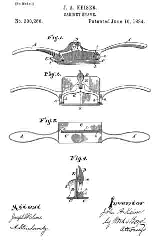
Figure 1 is a perspective view of my invention with the bit removed. Fig. 2 is a front elevation of my improvement with the bit in position for use. Fig. 3 is a bottom plan view of Fig. 2. Fig. 4: is a vertical section on line x x, Fig. 2.

A A represent the handles of my improved shave.

B represents the central portion of the stock of the shave, which, with the handles, is preferably made of malleable iron, cast in one piece. a represents ears cast on and with the stock B.

C represents the swiveling or detachable bit-face; C’, the stationary bit-face, which forms a part of the stock B.

b represents ears attached to the face C, and provided with pivots i, which hinge the ears b to the ears a.

d represents a yoke or bar connected to the ears b.

The parts C, b, b, and d are made of metal formed in one piece, and arranged so as to more freely upon the pivots i.

D represents a cam connected by pivot c to the center of the yoke d.

E represents the bit or knife, which is made to fit into the head B, as shown in Figs. 2 and 4. In order to hold the knife in position by detachable fastenings, it is essential to have it gripped at two points — first, at or near the cutting edge, and, second, at the central point of the knife, sufficiently near the upper end to prevent its rocking or moving. To accomplish this I provide lugs h, at each end of the cutter E on the bottom of face C, and adapted to bear against the cutter E upon each side of the shaving-slot L.

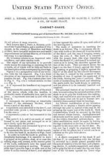
The mode of operation in inserting the knife is as follows: Fig. 1 represents the device with knife or bit removed from the stock of the shave and the cam D hanging loosely upon the yoke d. The knife E is inserted with the proper feed, (the edge depending below the faces C C’,) and cam D is turned upward so as to bring the shoulder against the face ofthe knife. This movement draws the lugs h, on the face C firmly against the blade E, pressing or gripping it tightly against the face C’ of the stock by the inward movement of the face C, caused by the pressure of the shoulder of cam D against the upper end of the knife, forcing the yoke d outward. This mode of constructing the stock and attaching the parts holds the knife firmly in position, and yet allows it to be instantly inserted and removed.

The principal feature of my invention consists in constructing the pivoted portion of the stock so as to grip the knife near the cutting-edge, and central at or near its upper end, and at the same time not be apt to become accidentally disconnected from its bearings.

An inferior modification of my invention would be to employ a thumb-screw passing through the yoke d, instead of the cam D, for gripping the upper end of the knife E. Such a construction would be covered by the first and second claims herein. Spokeshaves and other tools could be made in a similar manner as the within-described cabinet-shave. Another modification could be made by having the lugs h, attached to the face C’ and the shaving-slot in the same side of the bit-face. So, too, one lug h might be employed near the center of the bit-plane; but it would not be as efficient as the plan here shown.

I claim —

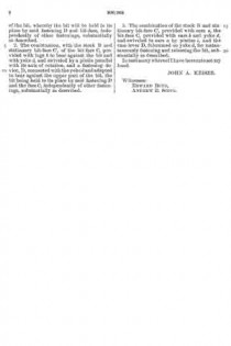
1. A shave composed of the stock B and bit-face C’, in combination with the bit-face C, swiveled by a pintle placed parallel with the axis of rotation of the bit-face, and a fastening device, D, suitably supported, and adapted to grip the bit at or near the top and force one of the bit-faces against the lower edge of the bit, whereby the bit will be held to its place by said fastening D and bit-face, independently of other fastenings, substantially as described.

2. The combination, with the stock B and stationary bit-face C’, of the bit-face C, provided with lugs h to bear against the bit and with yoke d, and swiveled by a pintle parallel with its axis of rotation, and a fastening device, D, connected with the yoke d and adapted to bear against the upper part of the bit, the bit being held to its place by said fastening D and the face C, independently of other fastenings, substantially as described.

3. The combination of the stock B and stationary bit-face C’, provided with ears a, the bit-face C, provided with ears b and yoke d, and swiveled to ears a by pintles i, and the cam-lever D, fulcrumed on yoke d, for instantaneonsly fastening and releasing the bit, substantially as described.

In testimony whereof I have hereunto set my hand.

JOHN A. KEISER.

Witnesses:
EDWARD BOYD,
ANDREW E. SCOTT.

No. 97,833 – Improvement In Tool For Cabinet-Makers (Richard W. Tanner) (1869)

[paiddownloads id=”158″]97833


United States Patent Office.


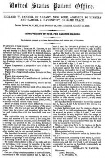
RICHARD W. TANNER, OF ALBANY, NEW YORK, ASSIGNOR TO HIMSELF
AND SAMUEL J. DAVENPORT, OF SAME PLACE.

Letters Patent No. 97,833, dated November 14, 1869; antedated December 11, 1869.
_________________

IMPROVEMENT IN TOOL FOR CABINET-MAKERS.

_________________

The Schedule referred to in these Letters Patent and making part of the same.

_________________

To all whom it may concern:

Be it known that I, RICHARD W. TANNER, of the city and county of Albany, State of New York, have invented a new and useful Tool for Cabinet-Makers, and other workers of veneer; and I do hereby declare that the following is a full, clear, and exact description thereof, reference being had to the accompanying drawings, making a part of this specification, in which —

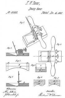
Figure 1 represents a perspective view of the invention.
Figure 2 is a vertical view of the same.
Figure 3 is a longitudinal section, through red line, in fig.2.
Figure 4 is a cross-section.
Figure 5 is a view of a modification of the form of the face-block.
Figures 6 and 7 are modifications, shown by end sections, of the said face-block.
Figure 8 represents the face-block with a plane-iron suited to this tool.

The nature of my invention consists in a tool-holder and a face-block properly secured together, and so arranged as to receive and hold a scraper or tooth-plane iron, or a straight plane-iron, or any other similar edge tool, by which the workmen plane, tooth, or scrape even the surface of the veneer.

There are many kinds of woods difficult to even on account of the waving or curling nature of the grain of the fibre. By this tool, any and all kinds of wood veneer may be evened and smoothed, with less labor and trouble, than with the hand-held tools now used.

The tool-holder may he constructed of wood or metal, and consists of a bar about a foot long, fur-
nished with a handle on each end, and is furnished with a holding-bar, pivoted to two eye-bolts, furnished with screws and set-nuts, also with a set-bolt, all of which are arranged and connected with the handled har, so as to fix and hold the scraper, plane-iron, or other similar tool, in any required position.

The face-block is secured to the said tool-holder by proper bolts or screws, and is provided with a mouth to permit the passage of the shavings from the wood, as it is being cut from off its surface.

To enable others skilled in the art to make and use my invention, I will proceed to describe it in reference to the drawings, and the letters of reference marked thereon, the same letters indicating similar parts.

One part of my invention consists in the tool-holder, constructed of the double-handled bar A, figs. 1, 2, and 3, and the tool-bar a, pivoted at each end, as shown in fig. 4, to the two eye-bolts e e, figs. 1 and 2.

The said eye-bolts e e pass through the handle-bar A, from the front to the rear, and are provided with thumb-nuts, by which the said tool-bar may be drawn nearer to the handled bar or further from it.

A screw-bolt, c, also works irorn the back ofthe handled bar A, and into it, and through to the tool-bar a, as shown in figs. 1, 2, and 3.

The scraper S, figs. 1 and 2, or plane-iron S’, fig. 8, is placed against the back of the tool-bar a, fig. 3, and between the handled bar A and the said tool-bar, and when thus placed, the said tool S or S’ is secured in its place, at any angle desired, by means of the said set-bolt c and eye-bolts e e.

The other part of my invention consists in the face-block B, shown in iigs. 1, 2. and 3.

The said face-block may be made of wood or metal, and is furnished with a mouth, b, the same as a plane, and may be either straight on its lower face, as in fig. 3, or concave, as in fig. 5, or the reverse, to fit the surface the tool is intended to operate upon, or they may be made either straight, or concave, or convex, longitudinally, as referred to, with moulding forms similar to those shown in figs. 6 and 7, or any other form, as may be required.

The said face-block is secured to the double-handled bar A., figs. 1, 2, and 3, by means of the screws o o, or their equivalents.

A plain flat face-block may be used, as shown in figs. 1 and 3, to which supplementary blocks B’ may be secured, as shown in figs. 5, 6, and 7, and when thus furnished in sets, together with the straps or plane-irons to correspond, the workman will have a tool which will enable him to perform and finish his work with greater ease and facility than can be done with the means they now have.

When a plane-iron, S’, is to be used, as in fig. 8, I would prefer to have the cutting-edge curved forward, as shown.

Having described my invention, What I claim, and desire to secure by Letters Pat~
ent, is —

The tool~holder, consisting of the block B, double-handled bar A, tool-bar a, eye-bolts e e, with their thumb-nuts, and the screw-bolt c, all arranged and constructed to operate as described, substantially as and for the purpose specified.

RICHARD W. TANNER.

Witnesses:
ALEX. SELKIRK,
J. A. BUCKBEE, Jr.