No. 1,059,137 – Plane (John P. Gage) (1913)
[paiddownloads id=”691″]1059137


UNITED STATES PATENT OFFICE.

_________________

JOHN P. GAGE, OF VINELAND, NEW JERSEY.

PLANE.

_________________

1,059,137. Specification of Letters Patent. Patented Apr. 15, 1913.
Application filed July 25, 1912. Serial No. 711,586.

_________________

To all whom it may concern:

Be it known that I, JOHN P. GAGE, a citizen of the United States, resident of Vineland, in the county of Cumberland and State of New Jersey, have made a certain new and useful Invention in Planes; and I declare the following to be a full, clear, and exact description of the same, such as will enable others skilled in the art to which it appertains to make and use the invention, reference being had to the accompanying drawings, and to letters or figures of reference marked thereon, which form a part of this specification.

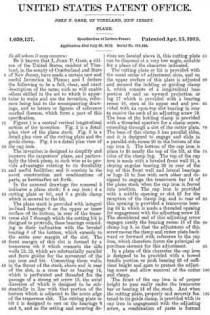
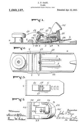
Figure 1 is a central vertical longitudinal section of the invention. Fig. 2 is a detail plan view of the plane stock. Fig. 3 is a detail plan view of the cutting plate and the guide clamp. Fig. 4 is a detail plan view of the cap iron.

The invention is designed to simplify and improve the carpenters’ plane, and particularly the block plane, in such wise as to provide advantages relating to its durability and useful facilities; and it consists in the novel construction and combinations of parts, as hereinafter set forth.

In the annexed drawings the numeral 2 indicates a plane stock; 3 a cap iron; 4 a cutting plate or bit, and 5 a guide clamp which is secured to the bit.

The plane stock is provided with integral inclined bearings 6 on the upper or inner surface of its bottom, in rear of the transverse slot 7 through which the cutting bit is designed to protrude, these bearings coinciding in their inclination with the beveled bearing 8 of the bottom, which extends to the acute rear margin of the slot. The front margin of this slot is formed by a transverse rib 9 which connects the side walls 12, 12, which are substantially parallel and form guides for the movement of the cap iron and bit. Connecting these walls, in the throat of the stock, above and in rear of the slot, is a cross bar or bearing 14, which is perforated and threaded for the passage of a strong set screw 15, the axial direction of which is designed to be substantially in line with that portion of the bottom which is adjacent to the acute edge of the transverse slot. The cutting plate or bit 4 is designed to rest on the bearings 6 and 8, and as the setting and securing devices are located above it, this cutting plate can be disposed at a very low angle, suitable for a plane of the character indicated.

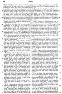
The cutting plate or bit is provided with the usual series of adjustment slots, and on the upper surface of this plate is adjusted and secured the holding or guiding clamp 5, which consists of a longitudinal base portion 16 and an upward projection or lug 17 which is provided with a bearing recess 18, open at its upper end and provided with an open-top slot bearing in rear to receive the neck of an adjusting screw 19. The base of the holding clamp is provided with a threaded aperture for a clamp screw, extending through a slot of the cutter plate. The base of this clamp 5 has parallel sides, and it is designed to engage and slide in a parallel-side recess 20 in the bottom of the cap iron 3. The bottom of the cap iron is plane to lit neatly the top of the bit, at the sides of the clamp lug. The top of the cap iron is made with a beveled front wall 21, a sloping angular bearing 22 in rear of the top of this front wall and lateral bearings or lugs 13 in line with each other and designed to engage the transverse bar 14 of the plane stock when the cap iron is forced into position. The cap iron is provided with a middle opening or slot 23 for the reception of the clamp lug, and in rear of this opening is provided a transverse bearing 24 in which is made a threaded opening for engagement with the adjusting screw 19. The shouldered end of this adjusting screw engages neatly the bearing recess 18 of the clamp lug 5, so that the adjustment of this screw moves the clamp and cutter plate backward or forward with reference to the cap iron, which therefore forms the principal or purchase element for this adjustment.

In a plane of this character the cap iron is designed to be provided with a bowed handle portion or push bearing 25 of sufficient height and span to protect the adjusting screw and allow removal of the cutter and clamp.

The front of the cap iron is of proper height to pass easily under the transverse bar or bearing 14 of the stock. And when the cutting plate, properly and securely fastened to its guide clamp, is provided with its cap iron in engagement with the adjusting screw, a combination of parts is formed which is designed to be placed on the bottom inclines of the stock and, if the set screw 15 is raised, will easily slide forward to position. In normal position the bearings 13 of the cap iron abut against the bar 14 of the stock, and the sloping bearing 22 lies under this bar. The screw 15 being now set down firmly against this sloping bearing, operates to drive the cap iron forcibly home against the transverse bar or bearing 14, and to clamp the cap iron firmly in place on the cutter plate. Adjustment of the bit is easily effected by means of the adjusting screw of the cap iron.

This plane is designed to be in a manner self-setting as its cap iron and plane iron fit together accurately beforehand, and when simply laid in place will slide forward to true position. When the cutting plate is properly secured to its guide clamp, no adjustment of the holding or setting parts is required, except in regard to the operation of the set screw and the adjusting screw. The simple devices of this plane can be taken apart and put together exactly as they were in a few seconds.

The setting and holding devices of the plane are placed above the cutting plate, in such wise that the latter may be arranged at as low an angle as may be required. The cap and plane iron are forced to accurate position and held therein by a single set screw, and without other care and attention than is required to turn the screw forcibly home.

In taking out the bit and cap iron no movement of the adjusting screw is required. The set screw being loosened up sufficiently, the cap iron, guide clamp and cutting plate will slide back and, without moving the adjusting screw, the cap-iron can be lifted from the cutter plate. Upon replacing the parts without adjustment of the screw of the cap iron, the bit takes its former position with relation to the cap iron accurately, so that when placed in the stock the cap iron will take normal position therein and there will be no change in its shaving adjustment. It is designed to provide in this plane practical operating parts which will when once adjusted always go together in accurate and true position with relation to each other to secure the same thickness of shaving without further operation of means of adjustment.

Having described the invention, what I claim and desire to secure by Letters Patent is:

1. In a plane, a stock having a threaded bearing, a cutter plate, a slotted cap iron on said plate having a threaded bearing, a guide clamp for said plate having an upward projecting bearing lug engaging the slot of the cap iron, an adjusting screw in the threaded bearing of the cap iron engaging said bearing lug, and a set screw in the threaded bearing of the stock engaging the cap iron.

2. In a plane, a stock having bottom inclines extending to its cutter slot, a cutter plate, a slotted cap iron provided with an adjusting screw, a guide clamp secured to the upper face of said plate and engaging the slot of the cap iron and having a bearing engaging said adjusting screw, and a set screw for the cap iron engaging a bearing of the stock.

3. In a plane, the combination with a stock having lateral parallel guide walls, bottom inclines and a threaded bearing over said bottom inclincs and a cutting plate engaging said inclines, of a cap iron engaging said guide walls and said cutting plate, a guide clamp for the cutting plate and engaging the cap iron, a set screw engaging the threaded bearing of the stock, and means in connection with said cap iron for adjusting said guide clamp and its plate to said cap iron.

4. In a plane, a stock having bearing and a threaded bearing in its throat, a cap iron having a front sloping bearing and lateral lugs to engage said transverse bearing, a cutter plate, means for adjustably connecting the cutter plate and cap iron and a set screw engaging the threaded bearing of the stock and the sloping bearing of the cap iron.

5. In a plane, a stock having bottom inclines and a threaded transverse bar over the same, a cap iron having a sloping front bearing and lugs to engage said bar, a guiding clamp for the cutter plate having sliding engagement with said cap iron, and means in connection with the latter for adjusting the guiding clamp and its cutter plate.

6. In a plane, the combination with a plane stock having bottom inclines, a threaded bearing over the same and a set screw therein, of a cutter plate on said inclines, a guiding clamp secured to the top of the cutter plate, a cap iron engaging the top of the cutter plate, and an adjusting screw engaging the cutter plate, and an adjusting screw engaging the guide clamp and the cap iron.

7. In a plane, the combination with a plane stock having bottom inclines and a set screw engaging a bearing of said stock above said inclines, of a cutter plate on said inclines, a guiding clamp secured to said cutter plate, an adjusting screw engaging said guiding clamp, and a normally stationary cap iron engaging the stock, the cutter plate, the guiding clamp, the set screw and the adjusting screw.

8. In a plane, a stock having bottom inclines, a set screw engaging a bearing of said stock above said inclines, a cutter plate on said inclines, a guiding clamp secured to the top of said plate, a normally stationary cap iron clamped on top of said plate by the set screw, and an adjusting screw connecting the cap iron and the guiding clamp.

9. A plane having a parallel-wall stock, low bottom inclines, and a bearing of said stock substantially over the cutter slot, a cutter plate on said inclines, a guiding clamp secured to the top of the cutter plate, a normally stationary cap iron on top of said cutter plate, an adjusting screw connecting the cap iron and the guiding clamp, and a set screw in a bearing of said stock engaging said cap iron.

10. In a plane, a parallel-wall stock having a transverse bearing, a cutter plate, a cap iron normally abutting against said bearing, a guiding clamp on top of said cutter plate, an adjusting screw, a set screw, and means in connection with said cap iron and set screw for forcing the cap iron to normal position against said bearing.

11. In a plane, a parallel-wall stock having a threaded transverse bearing in its throat, a cutter plate, a guiding clamp secured to its top, a cap iron engaging said clamp and abutting against the transverse bearing and having a push handle, an adjusting screw connecting said cap iron and guiding clamp, and a set screw engaging said transverse bearing and the cap iron.

12. In a plane, the combination with a parallel-wall stock, a transverse threaded bearing bar in its throat and a set screw in said bar, of a cutter plate, an adjustable clamping guide secured thereon, and a cap iron having normal position abutting said bar and engaged by said set screw.

13. In a plane, the combination with a stock and a threaded transverse bar in its throat, of a cutter plate, a guiding clamp above the cutter plate, a cap iron, means of adjustment connecting the guiding clamp and its cutter plate to the cap iron, and a set screw engaging said threaded transverse bar.

14. A cap iron of a plane having a central guide slot to engage a projection of a clamp for the bit, a threaded bearing in rear of said slot for an adjusting screw to engage said clamp, lateral lugs controlling its normal position in the stock, and a sloping angular bearing adapted to operate under the pressure of a set screw of the stock to force the cap iron to normal position.

15. A plane having in its throat a transverse bearing bar, a cutter plate, movable guiding means for clamping said cutter plate, movable means for adjusting and holding the clamping means, and means in connection withsaid transverse bearing bar for forcing the adjusting and holding means to normal fixed position against said transverse bar.

16. The combination with a parallel-wall stock having a transverse bar and bottom inclines, of a sliding cutter plate, a guide clamp carried thereby, a cap iron engaging said guide clamp, means of adjustment connecting the guide clamp and cap iron, and means for securing the cap iron in its lowest position against the transverse bar.

In testimony whereof I affix my signature, in presence of two witnesses.

JOHN P. GAGE.

Witnesses:
SADIE HOFFMAN,
H. D. STANNARD.

_________________

Copies of this patent may be obtained for five cents each, by addressing the “Commissioner of Patents, Washington, D. C.”
_________________

No. 485,923 – Truing Device For Bench-Planes (John Porcius Gage) (1892)

[paiddownloads id=”488″]485923


UNITED STATES PATENT OFFICE.

_________________

JOHN PORCIUS GAGE, OF VINELAND, NEW JERSEY.

TRUING DEVICE FOR BENCH-PLANES.

_________________

SPECIFICATION forming part of Letters Patent No. 485,923, dated November 8, 1892.
Application filed March 31, 1892. Serial No. 427,209. (No model.)

_________________

To all whom it may concern:

Be it known that I, JOHN PORCIUS GAGE, a citizen of the United States, and a resident of Vineland, in the county of Cumberland and State of New Jersey, have invented certain new and useful Improvements in Truing Devices for Bench-Planes; and I do declare the following to be a full, clear, and exact description of the invention, such as will enable others skilled in the art to which it appertains to make and use the same, reference being had to the accompanying drawings, and to letters of reference marked thereon, which form a part of this specification.

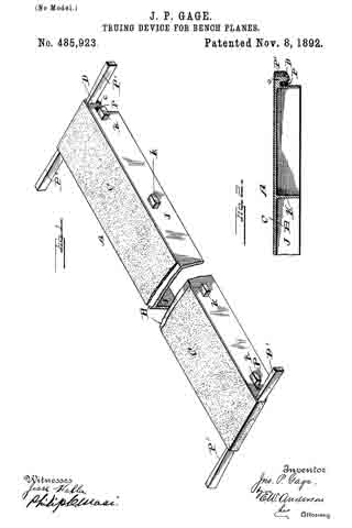
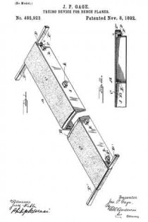
Figure 1 of the drawings is a representation of the device and is a perspective view. Fig. 2 is a longitudinal section of same.

This invention relates to certain novel devices for truing up or facing off the working or face side of carpenters’ bench-planes; and it consists in the novel construction and combination of parts, as hereinafter specified.

The invention more particularly consists in providing an abrasive surface held upon a suitable support in such a manner that all parts thereof will in so far as possible lie in the same plane, so that by rubbing the working face of the plane over such surface said face will be left perfectly true and smooth, which is a necessary qualification for a tool of this character. For truing up wooden planes this abrasive surface consists in a strip of ordinary sandpaper arranged in the manner above specified, while with metal planes emery-paper is employed.

In the accompanying drawings I have illustrated a convenient and effective manner of arranging the abrasive material, which consists in providing an elongated frame or table A, formed from a heavy metal casting having the horizontal portion B, the surface of which is in so far as possible a true plane, and is supported by the integral vertical depending flanges J, reinforced at intervals by the transverse portions K. Along the lateral outer faces of the flanges J are projecting lugs k, located at intervals, by means of which the table may be rigidly held in a stationary position in a suitable block or support. Over the upper surface of the horizontal portion B is tightly stretched a strip of sand or emery paper C, which is made secure at its ends in such a manner as to insure against an endwise or lateral displacement. In the drawings I have shown this as effected by bringing the ends of the paper over the ends of the frame or table and under depending flanges c, between which flanges and the ends D of the table are driven wedges P. Tapered wedges P are also driven under the paper from opposite sides against the flanges c. Should the paper become slack, these wedges may be driven in a greater distance. The heavy casting forming the table or support forms an effective means for the purpose, in that it is free from any vibration and renders the operation of the device very satisfactory. It will be understood, however, that I do not desire to limit myself to any especial devices for holding the paper in place, as such devices may be varied without departing from the spirit and scope of this invention.

Having described this invention, what I claim, and desire to secure by Letters Patent, is —

The herein-described device for truing up the working faces of bench-planes and other articles, said device comprising a heavy oblong rectangular metal casting having a true upper horizontal surface and formed at its ends with the under transverse lugs and a strip or piece of material provided with an abrasive surface stretched tightly over the true surface of said casting, the ends of said strip or piece being extended over the ends of the casting and clamped in said under transverse lugs, substantially as specified.

In testimony whereof I affix my signature in presence of two witnesses.

JOHN PORCIUS GAGE.

Witnesses:
JOHN S. GAGE,
W. W. BENTHALL.

No. 339,872 – Bench-Plane (John Porcius Gage) (1886)

[paiddownloads id=”409″]339872


UNITED STATES PATENT OFFICE.

_________________

JOHN PORCIUS GAGE, OF VINELAND, NEW JERSEY.

BENCH-PLANE.

_________________

SPECIFICATION forming part of Letters Patent No. 339,872, dated April 13, 1886.
Application filed January 16, 1886. Serial No. 188,770. (No model.)

_________________

To all whom it may concern:

Be it known that I, JOHN PORCIUS GAGE, a citizen of the United States, residing at Vineland, in the county of Cumberland and State of New Jersey, have invented certain new and useful Improvements in Bench-Planes; and I do declare the following to be a full, clear, and exact description of the invention, such as will enable others skilled in the art to which it appertains to make and use the same, reference being had to the accompanying drawings, and to letters or figures of reference marked thereon, which form a part of this specification.

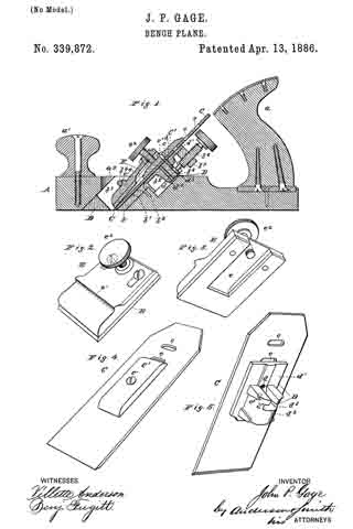
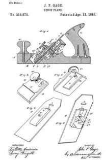
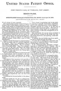
Figure 1 of the drawings is a representation of this invention, and is a vertical longitudinal section. Fig. 2 is a perspective view of one of the clamping-plates. Fig. 3 is another view of the same plate. Fig. 4 is a perspective view of the tool, and shows the clamp upon the upper side or front. Fig. 5 is a rear view of the tool, and shows the clamp upon the rear or under side.

This invention has relation to improvements in bench-planes; and it consists in the construction and novel arrangement of parts, hereinafter set forth, and pointed out in the claims.

The object of the invention is to provide a bench-plane in which the bit or cutting-tool may be properly adjusted both laterally and longitudinally, and when adjusted laterally the longitudinal movement will be in a straight line, and with its edge parallel to the lower surface of the plane-stock.

In the accompanying drawings, A designates the plane-stock, of rectangular shape, and provided with the handles a a’, firmly secured by screws or otherwise to its upper surface, and respectively near its front and rear ends.

a2 is the slot for the tool-holder in the plane-stock.

B is the holder for the bit or cutting-tool, secured in the slot a2. The holder B is provided with the inclined rear plate, b, secured in the slot a2 by means of the slots b’ and screws b2 and the parallel side plates, b3 b3, which lie against the side of the slot a2, and are connected by the transverse rod b4, as shown.

b5 is a larger longitudinal slot in the plate D, serving a purpose hereinafter explained, and b6 is an adjusting-screw, which engages a threaded opening in a stud, b7, on the rear surface of the top of said plate. The screw b6 has a suitable milled head on its upper end, and a circular or disk-like enlargement, b8 its lower end.

The tool-holder B is at its lower end flush with the lower surface of the stock, and has the usual transverse tool-opening in the said lower end.

If desired, the tool holder may be so made as not to extend through the stock.

C is the bit or cutting-tool, provided with the series of transverse slots c c and a proper cutting-edge at its lower end.

C’ is a clamping-plate, through a central opening in which the screw c’ passes. The said screw also passes through any one of the slots c of the tool, upon the front surface of which the clamp rests. The end of the screw c’ engages in one of the threaded openings d d in the guide-clamp D, which lies upon the rear surface of the tool C.

The clamp D consists of a rectangular plate, d’, and a guide-block, d2, on the rear surface of said plate. The block d2 has at its upper end the semicircular recess d3, open at top. Into this recess the disk b8 enters and turns freely therein, the block d2 passing through the slot b5 of the tool-holder. The sides of the block are squared, and made of proper dimensions to fit snugly within the slot.

It is evident from the foregoing that by turning the screw b6 up or down the cutting-tool C may be raised or lowered, and that the slot b5 will form a guide for the block d2 and for the tool clamped thereto by the means described, so that the edge of the tool, being made parallel to the lower surface of the stock, will always remain so, either when raised or lowered. Should the edge be not parallel to the bottom, the tool can be partially rotated between the clamps C’ and D’ by hand-pressure or by a light blow from a hammer, the screw c’ being loose enough to permit this. The slots c allow the position of the clamps C’ and D’ on the cutting-tool to be varied when necessary. Each slot c also allows the tool to be adjusted laterally between the clamps.

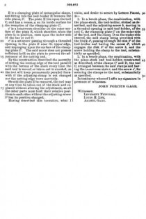
E is a clamping-plate of rectangular shape, and fitting into the tool-holder B between the side plates, b3. The plate E lies upon the tool C, and has a recess, e, on its inside surface for the reception of the clamping-plate C’.

e’ is a transverse shoulder on the outer surface of the plate E, which shoulder, when the plate is in position, rests upon the under side of the bar or rod b4.

e2 is a set-screw passing through a threaded opening in the plate E near its upper edge, and impinging upon the surface of the clamping-plate C’. The said screw does not possess sufficient hold on the plate to prevent the adjustment of the cutting tool.

By the construction described the necessity of setting the cutting-edge of the tool parallel with the bottom of the stock every time the said tool is moved or taken out is avoided, as the tool will keep permanently parallel therewith if the adjusting-clamp is not changed nor the cutting-edge worn unevenly.

Should the plate E be removed, the tool may at any time be taken out of the stock and replaced without altering the adjustment, as all the other parts must hold their relative positions to each other without the adjusting-screw b6 has its position changed.

Having described this invention, what I claim, and desire to secure by Letters Patent, is —

1. In a bench-plane, the combination, with the plane-stock, the tool-holder, slotted as described, and the adjusting-screw b, moving in a threaded opening in said tool-holder, of the tool C, the clamping-plate C’ on the outer side of the tool, and the clamp D on the under side thereof, the said clamp being provided with the block d2, passing through the slot b5 of the tool-holder and having the recess d3, which engages the disk b8 of the screw b, and the screw holding the clamp to the tool, substantially as specified.

2. In a bench-plane, the combination, with the plane stock and tool-holder, constructed as described, of the clamps C’ and D, the tool C, arranged between the said clamps and having the transverse slots c, and the screw c’, for securing the clamps to the tool, substantially as specified.

In testimony whereof I affix my signature in presence of witnesses.

JOHN PORCIUS GAGE.

Witnesses:
LEVERETT NEWCOMB,
LOUIS H. LEE,
ASAHEL GAGE.

No. 323,804 – Bench-Plane (John P. Gage) (1885)

[paiddownloads id=”398″]323804


UNITED STATES PATENT OFFICE.

_________________

JOHN P. GAGE , OF VINELAND, NEW JERSEY.

BENCH-PLANE.

_________________

SPECIFICATION forming part of Letters Patent No. 323,804, dated August 4, 1885.
Application filed April 23, 1885. (Model.)

_________________

To all whom it may concern:

Be it known that I, JOHN P. GAGE, a citizen ofthe United States, residing at Vineland, in the county of Cumberland and State of New Jersey, have invented certain new and useful Improvements in Bench-Planes; and I do declare the following to be a full, clear, and exact description of the invention, such as will enable others skilled in the art to which it appertains to make and use the same, reference being had to the accompanying drawings, and to letters or figures of reference marked thereon which form a part of this specification.

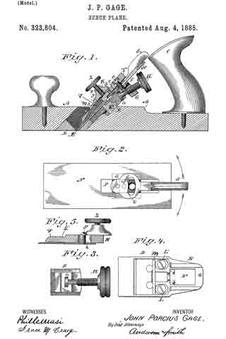
Figure 1 of the drawings is a representation of a longitudinal section of my invention. Fig. 2 is a view of the cutter and the pivoted finger-lever removed from the plane. Fig. 3 is a view of the adjusting-screw and cutter-bearing removed. Fig. 4 is a detached view of the bearing-plate, and Fig. 5 is a sectional view of the fellow plate and cup-plate with the bearing-screw and casting applied.

This invention has relation to improvements in carpenters’ planes; and it consists in certain novel devices, as hereinafter set forth, and pointed out in the appended claims.

In the accompanying drawings, the letter A designates the body of the plane, which is formed with an oblique transverse slot, B, for the cutter and its. adjusting devices. C is the handle.

D is a metal bearing, which is set into the oblique slot B, and is secured therein. The lower face of this bearing is flush with the bearing-face of the plane-body, and may be made a little concave in its middle portions, or between its front and rear bearing-edges. This metal bearing is provided with an extension, E, backward and upward, which is slotted at F, and has a threaded bearing at G for the adjusting-screw H. It is also provided with lateral stops K.

L L are the elongated openings or slots through which the fastening-screws pass. A transverse bearing, m, is provided, usually in rounded or rod form, which is located upward and forward from the main face of the casting, on which the cutter rests.

N is the cutter, slotted at P, and provided with an under bearing, R, which is designed to engage the enlarged end a of the adjusting-screw. This bearing descends into the opening B of the casting D when the cutter is applied in position.

S is a lever having its fulcrum-bearing c in the slot of the cutter, and engaging a stud, d, of the bearing B, or of its fellow plate T, which is firmly secured to said bearing B, usually by a screw, e. The handle of the lever S projects backward and upward within easy reach of the fingers. The object of this lever movement is to enable the operator to adjust the cutter laterally, so that when its cutting-edge is inclined or out of trim a single movement of the lever to the right or left, as the case may require, will correct the deviation and bring the cutting-edge into true relation with the bearing-face of the plane. Other forms of lever-connections may be employed with the cutter, or the adjustment may be made by means of lateral screws, or a screw may be employed, extending downward and forward, to operate an eccentric in connection with the cutter. Many devices to effect this lateral adjustment of the cutter-plate will occur to those skilled in the art.

V is the cap-plate, which is adjustable by means of screws g g passing through siots h h, in the fastening-piece or top casting, V, which carries the bearing-screw Z. This top V is formed with a concave rounded bearing, k, adapted to engage the transverse rod an and hold the fastening-piece or cap-plate firmly in position.

Having described this invention, what I claim, and desire to secure by Letters Patent, is —

1. In a plane, the combination of the slotted cutter, the under bearing, B, having a stud, d, and operated by means of the adjusting-screw, the fellow plate, screw connecting the fellow plate and bearing R, lever S, and its fulcrum-bearing c, arranged in the slot of the cutter, substantially as specified.

2. The combination of the slotted cutter, a bearing arranged beneath the same, with a stud passing through the slot of the said cutter, a fellow plate connected with the said under bearing, the finger-lever, and its fulcrum-bearing, as c, arranged in the slot, wherby lateral deviations of the cutting-edge may be corrected, substantially as specified.

3. A plane having an lever adapted to correct deviations in the edge of the cutter, which lever has its lower end pivoted in a longitudinal slot of the cutter, and provided with a stud to engage and move laterally a fulcrum-bearing in the said slot, substantially as specified.

In testimony whereof I affix my signature in presence of two witnesses.

JOHN P. GAGE.

Witnesses:
THEO. MUNGEN,
PHILIP C. MASI.

No. 271,569 – Bench-Plane (David A. Bridges) (1883)

No. 271,569 – Bench-Plane (David A. Bridges) (1883)

[paiddownloads id=”328″]271569


UNITED STATES PATENT OFFICE.

_________________

DAVID A. BRIDGES, OF VINELAND, NEW JERSEY, ASSIGNOR OF THREE-FOURTHS TO JOHN GAGE, OF SAME PLACE.

BENCH-PLANE.

_________________

SPECIFICATION forming part of Letters Patent No. 271,569, dated January 30, 1883.
Application filed April 17, 1882. (No model.)

_________________

To all whom it may concern:

Be it known that I, DAVID A. BRIDGES, a citizen of the United States, and a resident of Vineland, Cumberland county, and State of New Jersey, have invented certain Improvements in Bench-Planes, of which the following is a specification.

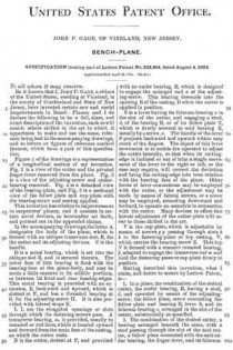
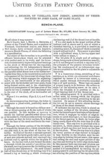
The object of this invention is to provide an efficient bench-plane which can be adjusted with perfect ease to its work; and the invention consists mainly in providing fixed bearings in the stock or throat-iron for the cap-plate, and adjusting the bit independently thereof, in the construction and novel arrangement of the parallel-sided throat-iron or bit-holder having the wear-face, in the construction and novel arrangement of the transverse bit-clamp forming the bearing which engages the adjusting-screw, in the combination of the adjusting-screw with the bit-holder and wear-plate, these being formed entire, and in the construction and novel arrangement of the base-plate of the handle let into a recessed and depressed seat in the rear of the stock, all as hereinafter set forth.

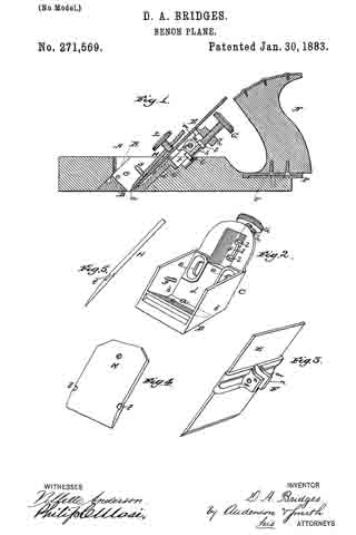
Figure 1 is a section; Figs. 2, 3, 4, and 5 are details.

In the accompanying drawings, the letter A designates a plane-stock, preferably made of wood.

Through the stock is formed an oblique mortise or throat-opening at B, the walls of which are parallel. In this mortise or opening is seated the inclined parallel-sided throat-iron or bit-holder G, which extends entirely through the stock, so that its lower surface, D, is flush with the base of the stock and forms the wear-plate.

Through the lower portion of the bit-holder C is made the throat-slot a, which extends from one side wall, b, to the other of the iron bit-holder. In front of the slot a extends upward and forward the bevel guide-wall c, and in rear of said slot extends upward and rearward the inclined wall d, against which the bit-plate E bears. In the rear wall, d,are formed the slots c, through which the screws e’ are driven into the stock, serving to secure the bit-holding iron in position after adjustment. On each lateral wall of this throat-iron or bit-holding iron C is formed a lug or bearing, g, which overhangs the bearing-wall d of the throat-iron at its side.

F is a slot made in the upper portion of the inclined wall d, above and in rear of which a threaded bearing, h, is provided to receive an adjusting-screw, G, the axis of which is parallel to said inclined wall d. This screw is provided with a cylindrical stem, k, having upper and lower collars or stops, l.

The bit-plate E is single and of ordinary shape, being made without perforation usually, as it is not designed to attach a cap-iron to it, the principle of the present invention involving the employment of an independent cap-iron not attached to the bit-plate or adjustable therewith.

F is a transverse clamp, consisting of two sections, m m, which are connected and drawn together by means of a transverse screw, s, which passes through downwardly-extended lugs it of said sections. These lugs are made of proper length to fit between the collars or stops l of the adjusting-screw on its stem k when the bit-plate is in position on the inclined bearing-wall d of the throat-iron.

The adjusting-screw G is provided with a milled head, by turning which the bit-plate can be raised or lowered, according to the set required. By means of this adjusting device the bit can be set to remove coarse shavings or those of the finest character.

H indicates the cap-iron, which is placed on the upper surface of the bit-plate, extending under the lateral lugs or bearings g of the throat-iron, which it engages by means of edge-recesses or catch-bearings t, so that its position in the throat-opening is fixed, its lower edge being nearly flush with the wear-face D of the throat-iron. This cap-iron is provided with a set-screw, L, which passes through the upper portion of said cap-iron and bears on the face of the bit-plate. When the cap-iron is in place the lower portion or edge thereof is brought to bear forcibly on the bit-plate near its cutting-edge by turning this set-screw, this operation raising the rear and upper portion of the cap-iron and forcing its lower edge downward. In this manner both cap-iron and bit-plate are secured in position, and when adjustment is needed it is accomplished by turning the adjusting-screw G and moving the bit-plate without altering the position of the cap-iron, which remains stationary and in the same position for every position of the bit-plate. The cap-plate, being of metal (usually iron) and of moderate thickness, possesses sufficient elastic or yielding properties to permit the bit to slide along the point of the set-screw I, when operated by the adjusting-screw, as described.

The handle N is provided with a base-plate, P, which is let into a seat, v, in the rear portion of the stock, this seat being recessed in the stock for this purpose. Usually the rear end of the stock is cut away or depressed, as indicated at w, and in the depressed surface the recess-seat in is formed. The position of the handle is such that when it is grasped the milled head of the adjusting-screw G will be within easy reach of the fingers, so that the position of the bit plate can be adjusted while the plane is in operation. The bit-plate need never be removed from this plane except for repairs or sharpening, all required adjustments being accomplished with the greatest ease while the bit is in place.

Having described this invention what l claim, and desire to secure by Letters Patent, is —

1. In a bench-plane having fixed bearings in its throat for the cap-iron, the combination, with a cap-iron having lateral notches to engage said fixed bearings of the independently-adjustable bit-plate E, adapted to be moved in the direction of its length without moving the cap-iron, substantially as specified.

2. The combination, with the oblique throat-iron and its adjusting-screw G, of the bit-plate E, its clamp sections having lugs n, and the transverse connecting-screw, substantially as shown and described.

3. The combination, with the oblique throat-iron and adjusting-screw G, seated therein, of the bit-plate E, having lugs n, engaging the said adjusting-screw, and the stationary cap-iron and its adjusting-screw, substantially as and for the purposes specified.

In testimony whereof I have signed my name to this specification in the presence of two witnesses.

DAVID A. BRIDGES.

Witnesses:
CHARLES F. KELLOGG,
ALBRO S. BROWN.