No. 14,363 – Bench Plane (Ebenezer Mathers) (1856)

[paiddownloads id=”29″]14363


UNITED STATES PATENT OFFICE.

_________________

EBENEZER MATHERS, OF MORGANTOWN, VIRGINIA.

BENCH-PLANE.

_________________

Specification of Letters Patent No. 14,363, dated March 4, 1856.

_________________

To all whom it may concern:

Be it known that I, EBENEZER MATHERS, of the town of Morgantown, county of Monongalia, State of Virginia, have invented a new and useful Improvement in Bench-Planes; and I do hereby declare that the following is a full, clear, and exact description of the construction and operation of the same, reference being had to the accompanying drawings, making a part of this specification, with letters of reference marked thereon.

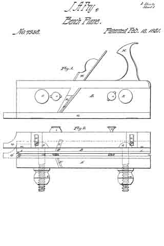
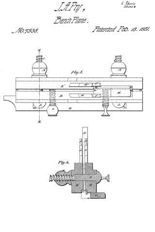
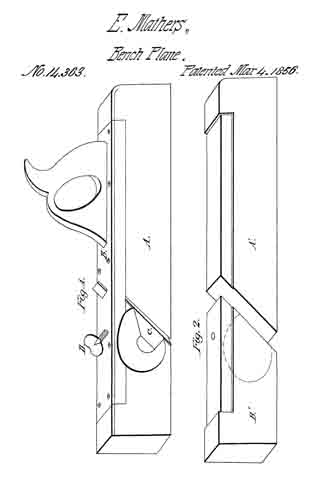
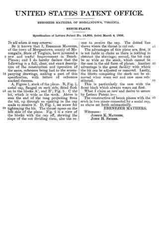
A, Figure 1, stock of the plane. B, Fig. 1, metal cap, flanged on each side, fitted flush on to the blocks A’, and B’, Fig. 2. C the bit, which is wide as the stock. Above is seen the end of the tang projecting from the bit, up through an opening in the cap made to receive it. D, Fig. 1, set screw for tightening the bit. The throat opens on the left side of the plane. Fig. 2 is a view of the blocks with the cap off, showing the slope of the cut dividing them, also the recess to receive the cap. The dotted line shows where the throat is cut out.

The advantages of this plane are, first, it is not liable to choke as there is nothing to obstruct the shavings; second, the bit may be as wide as the stock, which cannot be the case in the old form of planes. Another advantage is the great facility with which the bit can be adjusted or removed. Lastly, the blocks composing the stock can be removed when worn out and new ones substituted.

This is particularly the case with the front block which always wears out first.

What I claim as new and desire to secure by Letters Patent is —

The construction of bench planes with the stock in two pieces connected by a metal, cap, as above set forth substantially.

EBENEZER MATHERS.

Witnesses:
JOSEPH K. MATHERS,
JOHN H. SNIDER.

No. 7,938 – Tonguing, Joining And Rabbeting Plane (John A. Fry) (1851)

[paiddownloads id=”6″]7938


UNITED STATES PATENT OFFICE.

_________________

JOHN A. FRY, OF EDINBURG, VIRGINIA.

TOOL FOR TONGUING, JOINING, AND RABBETING.

_________________

Specification of Letters Patent No. 7,938, dated February 18, 1851.

_________________

To all whom it may concern:

Be it known that I, JOHN A. FRY, of Edinburg, county of Shenandoah and State of Virginia, have invented a new and useful Tonguing Plane, and that the following is a full, clear, and exact description thereof, reference being had to the accompanying drawings, which make part of this specification.

The purposes of my invention are to make a tool by the use of which the workman may make tongues of different thicknesses, the same tool being capable of both tonguing and jointing the stuff, and to make the same tool answer the purpose of a rabbetlng plane. The tool might be called a combined jointing-tonguing and rabbeting plane. The advantage of such a tool is that boards or plank of different thicknesses may be tongued with one implement, and yet each may have a tongue out upon it of a thickness adapted to that of the plank. It also enables the workman to diminish the thickness of any tongue if found too thick for the easy putting together of his work. It also saves the trouble of keeping on hand or carrying about three distinct tools instead of one, to perform the three or four operations for which this implement is intended.

My plane is made of two distinct parts or bodies B and B’, Figures 2 and 3; wherein, Fig. 2, is an underside plan and Fig. 3 a top plan. These parts may, by turning back the screws s, s, and screwing up the nut N, N, on the screws S, S, be brought close together, closing up the space m m between the two bodies. When the bodies are thus brought together, the instrument may be used first to joint a board, which it will do if the adjustable guide or gage G, Fig. 2, be brought into the position indicated by the dotted lines, G’. This position it can take by slackening the set screws r r, and slipping the gage piece till the screws occupy the opposite ends of the slots o, o, to those where they are seen in the figure. The plane iron P’ will then serve as a jointing cutter to straighten the edge of the board before commencing the tonguing, the board resting on its edge for both operations.

When a tongue is to be cut, after jointing the board, the slide or gage G is restored to the position seen in the figure (2) or so nearly to it as is required by the thickness of the plank. The two bodies B, B’ may then be either kept close together or they may be separated apart to a distance required by the thickness of the tongue intended to be formed. If they be kept close together the thickness of the tongue will be that of the two half grooves P, P’, but if they be separated by the adjusting screws s s, and fixed by the set screws S S, then will the thickness of the tongue be increased by the distance m of the separation of the two bodies. At whatever distance apart the bodies are set the guide or gage G, sliding along the face of the board determines the breadth of out which shall be made by the cutter P. The cutters P and P’ are both set inclined not only backward from the vertical, but also horizontally from their inner to their outer edges respectively. By this arrangement of the irons the chips or shavings are, when tonguing, thrown outward on the two opposite sides of the plane. The place of discharge is seen at R, in the side elevation of the body B, Fig. 1. The cutters P and P’ are held in place by the oblique wedges W and W’ Figs. 1 and 3.

The cutters have each two edges, one across the end and one on the inner side, whereby the side of the tongue is smoothed at the same time that the wood is cut away on both sides of it to form the jointed shoulders of the tongue. The edges along the sides also serve the purpose of diminishing the thickness of a tongue already made when such diminution becomes necessary.

The handle of the plane is seen at H, Figs. 1 and 3. It is permanently attached to the body B, but its base Q Q (Fig. 3) extends beyond that body and makes a projection which enters a notch M M, in the upper part of the body B’, which notch and projection serve to give a support in a longitudinal direction to the body B’ while the set screws S S confine it laterally to the body B.

When the plane is to be used for rabbeting the body B’ is wholly removed and the set screws S S may be taken out. Then by sliding the guide G on the set screws r r, till the edge w w coincides with or lies over x x, it may be then fastened for the purpose of using the plane to joint a board previous to cutting a rabbet. The plane iron P is driven down till its cross edge comes nearly or quite through the oblique slot V. The edge of the gage G together with the vertical side of the notch P, then serves as the face of the jointer, and the jointing cut is made not by the cross edges but by the side edge of the plane iron P. With the implement having its gage and cutter in the positions just described the board is jointed on its edge while it lies upon its face or flat side, the bottom of the notch or rabbet p resting upon the upper corner of the board and guiding or sustaining the plane.

The board having been jointed, is rabbeted without removing it from the bench. For this purpose, the tool is prepared by sliding the gage G into the position represented by the plain lines in Fig. 2, and the plane iron is set with its cross edge nearly on a level with the line x x, descending only far enough below that level to make its cut.

It is then used to out the rabbet without changing the position of the board, from that in which it lay while being jointed.

From the foregoing description it will be seen that the gage G is brought into use in combination with the notch P and the side edge of the cutter P to form a jointer for a board resting on its face, in a situation to be rabbeted ; that it is combined with the cross edge of the cutter P and with the half groove p to form the rabbeting plane; that when combined with the cutter P’ and the body B’ it forms a jointing cutter to joint a board, set up edgewise in a position to be tongued, and finally that the same gage G in combination with the two bodies B and B’, and the two cutters P and P’, it forms the tonguing plane. The parts of the tonguing plane just specified, together with the parts hereinbefore specified for setting the bodies B and B’ asunder and retaining them in place constitute an adjustable tongue cutter, whereby tongues may be out of different thicknesses to suit the thickness of the stuff or the purpose to which it is to be applied.

Fig. 4 is a cross section through x x Fig. 3, exhibiting the bodies B and B’ the gage G, the fastening screw S and its nut N together with an elevation of the wedges W, W’, plane irons P and P’ and the handle H.

What I claim as my invention and desire to secure by Letters Patent is —

1. So making a jointing, tonguing and rabbeting plane that the jointing and tonguing of a board while resting on its edge, and also the jointing and rabbeting of it while it lies on its flat side may all be performed with one planing tool in the manner substantially as herein described, and for the purposes herein set forth.

2. I also claim making the tonguing hand plane in such a manner as to enable the workman to make therewith tongues of various thicknesses substantially in the manner herein set forth, whereby I prevent the necessity of providing different tools to tongue planks of different thicknesses.

3. I also claim in combination with a divided body or plane stock, the two cutters having each a cross-cutting and a side-cutting edge and the means substantially as herein described for adjusting the distance apart of the two cutters and bodies whereby the plane is made capable of dressing the sides of a tongue to any desired thickness and at the same time to cut the shoulders as herein specified.

4. I also claim in combination with the gage G the use of the body B’ and the cross edge of the cutter P’ to constitute a jointer to straighten the edge of a board preparatory to tonguing it and while resting on its edge in a situation to receive the tonguing.

5. I also claim the gage G in combination with the notch p and the side edge of the cutter P, acting as herein described, as a jointing plane to straighten the edge of a board or plank resting on its flat side, in a position to have a rabbet out in the manner substantially as herein set forth.

JOHN A. FRY.

Witnesses:
GEORGE A. GRUNDSTAFF,
ISAAC RULY.

No. 7,543 – Scraper Used By Cabinetmakers (Hiram Carver) (1850)

[paiddownloads id=”5″]7543


UNITED STATES PATENT OFFICE.

_________________

HIRAM GARVER, OF EDINBURG, VIRGINIA.

SCRAPER USED BY CABINETIVIAKERS.

_________________

Specification of Letters Patent No. 7,543, dated August 6, 1850.

_________________

To all whom it may concern:

Be it known that I, HIRAM CARVER, of Edinburg, county of Shenandoah, and State of Virginia, have invented a new and useful Improvement in Cabinetmakers’ Scraping-Tools, and that the following is a full, clear, and exact description thereof, reference being had to the accompanying drawings, which make part of this specification.

The scraper in common use is a plate of steel of any convenient size and generally of uniform thickness, like a piece of common saw plate. An edge of this plate having been made straight or slightly curved, convexly outward is burnished on the edge with a piece of polished steel so as to raise a slight ridge or feathering on each corner as seen at e, e, and e’, e”, Fig. 1. Such plate is, when used to smooth off furniture, coach bodies, panelings and other work requiring to be brought to a smooth surface, usually held by the workmen between the thumbs and fingers of his two hands, and with the top inclined from him is operated by pushing, while the lower inclined feathered corner scrapes the surface and removes the irregularities left by the plane. This mode of using the scraper is excessively fatiguing to the lingers and thumbs and without great strength cannot be long pursued, nor without great steadiness of hand can the work be made of uniform smoothness. To remedy these inconveniences, and to make the scraper a convenient and efficient tool I furnish the scraping plate A with a stock (B) in which it is set, and held fast by set screws (C) or other equivalent device. The stock-frame D is a little wider than the plate A, and the stock has a slot quite through it, allowing the plate to come above the upper edge, as well as to descend below the lower edge of the stock.

E, E’, are cross pieces of the stock frame connecting together the side pieces D, D’, D D’ (Fig. 2) through which passes the axis F F of the scraper stock, having screws cut on the ends to receive the nuts G, G.

Along the lower and inner part of the side pieces D, D, are offsets I, I, (Fig. 2) and in these are sloping cavities or notches H, H’, within which the ends of the stock B are placed. The stock is thus capable of moving on its axis about one eighth of a revolution, more or less, and of being adjusted to any required angle of inclination to suit the work. This “notch” is also formed for the purpose of allowing the position of the stock and scraping plate to be reversed, so that instead of presenting the feather edge e’ to scrape the surface, that on the opposite corner, e”, may be brought into a position to work.

With the stock situated as seen in the dotted lines Fig. 1, the operator grasps the tool by the two handles D’, and resting the other end of the stock frame on the friction roller R, brings the edge e’ in contact with the surface to be scraped and with a pushing force scrapes a thin film of the material from the surface to be smoothed.

The purpose of the nuts G, G, (Fig. 2,) is to fasten the stock temporarily in one or the other position with the degree of its inciination properly adjusted according as the feather edge e’ or e” is intended to be used in scraping. When e’ is used the tool is pushed in the direction indicated by the arrow, and when B is reversed and brought toward a contact with the slope H, the operator takes the tool by the two handles D, D, and pushes in the direction opposite to that of the arrow, which brings the edge e” into action, and the forward end then rests on the friction roller R’.

I shall sometimes make two or more sides of the scraping plate capable of acting as scraping edges as e, e, and e’ e”, and shall form the outline variously, either straight, convex or concave, so as to adapt it to either plane convex or concave surfaces or to moldings of any kind which I may desire to smooth. Nor shall I confine the use of this tool to smoothing the surfaces of wood, but shall also apply it wherever found applicable, to scrape the surfaces of leather, horn, ivory, soft metals or any other solid substances requiring to be smoothed.

The rollers R, R’, prevent the scratching of the smoothed surface as well as guide the scraping edge. By the use of this roller the workman is relieved from the necessity of rubbing his hands upon the smoothed surface while sustaining the scraper as in the usual practice when holding it between his fingers.

What I claim as my invention and desire to secure by Letters Patent is —

1. The scraper stock set in a frame for holding and guiding the scraper so that the forward end only of the frame shall rest on the surface to be scraped and thereby enabling the workman to manage the tool with the whole hand, and apply a steady force; instead of using the fingers only as heretofore for that purpose.

2. I also claim reversing the position of the scraper stock and plate in the frame, whereby I am enabled to use both feather edges or corners of the plate successively without taking the plate from the stock as herein set forth.

HIRAM CARVER.

Witnesses:
WALTER R. JOHNSON,
JOHN B. STONER.