No. 510,096 – Bench-Plane (Jacob Siegley) (1893)
[paiddownloads id=”497″]510096


UNITED STATES PATENT OFFICE.

_________________

JACOB SIEGLEY, OF WILKES-BARRÉ, PENNSYLVANIA.

BENCH-PLANE.

_________________

SPECIFICATION forming part of Letters Patent No. 510,096, dated December 5, 1893.
Application filed May 21, 1892. Serial No. 433,924. (No model.)

_________________

To all whom it may concern:

Be it known that I, JACOB SIEGLEY, a citizen of the United States, and a resident of Wilkes-Barré, in the county of Luzerne and State of Pennsylvania, have invented certain new and useful Improvements in Bench-Planes, of which the following is a specification.

This invention relates to certain improvements in bench-planes, and the same consists of a cast-iron bottom and steel side-plates riveted to lugs of said bottom, and of a cap that is provided with a shoulder having set-screws, said shoulder resting on a transverse rod extending between the sides of the supporting frame and screws in said shoulder permitting the adjustment of the cap into higher or lower position, all of which will be fully described hereinafter and finally pointed out in the claims.

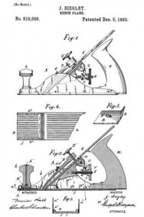
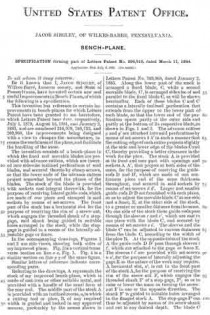
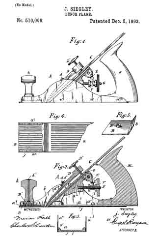
In the accompanying drawings, Figure 1 represents a side elevation of my improved bench-plane. Fig. 2 is a vertical longitudinal section of the same. Fig. 3 is a detail vertical transverse section on line 3 3, Fig. 2.

Fig. 4 is a bottom view of the front part of my improved bench-plane, and Fig. 5 is a perspective view of the throat-piece as detached from the plane.

Similar letters of reference indicate corresponding parts.

Referring to the drawings, A represents the frame of my improved bench-plane, which is composed of a cast-iron bottom plate a, provided with lugs a’ that are cast integral therewith, and of upright steel side plates a2 which are attached by rivets that are inserted into the lugs or bosses a’, as shown clearly in Fig. 3. By making the sides of steel plates a much lighter and more durable frame for bench-planes is obtained. To the rear part of the bottom plate a is attached the main handle H, while the knob h at the front end of the plane is provided with a spindle h’ having a threaded lower end that takes into an interiorly-threaded boss B’ of a detachable throat-piece B which is supported against the underside by the front part a3 of the bottom of the frame A, said bottom being a short distance from the lower edge of the frame, so as to provide for the throat piece B and bring the under side of the same accurately at a level with the under side of the main part of the bottom plate a, as shown in Fig. 2. The throat piece can be adjusted toward the blade C and cap D of the latter, as the boss of the same permits the shifting action to a certain extent in the opening of the front part a3 of the bottom plate, the knob h with its spindle h’ serving to tightly retain the throat piece on the front part of of the bottom plate. The rear end of the throat piece is provided with an upwardly inclined flange b, along which the shavings pass, as they are out off by the edge of the blade, the said flange guiding the shavings and preventing them from curling in passing up through the throat of the plane. The cap D is made tapering at its lower end, so as to bear on the blade C, while the upper end is provided with a screw D’ by which the blade C is rigidly held in position in the stock of the plane. The under side of the blade is provided with transverse grooves m, that are engaged by the tooth e of a fulcrumed arm E, the forked lower end E’ of which is engaged by a collared sleeve F that is adjustable on a fixed screw G on the fixed block J of the frame A so as to adjust thereby the blade in the stock. The cap D is provided with shoulder d which rests against the transverse rod d’ that connects the upper part of the steel side plates a2, as shown in Fig. 2, said shoulder being provided with set-screws d2 the lower ends of which bear against the transverse rod d’ said set-screws serving for raising or lowering the cap, so as to adjust it accurately in its relative position to the blade. The under side of the main part of the bottom plate a and the under side of the throat piece B are provided with longitudinal corrugations f by which the friction of the bottom of the plane with the surface to be planed is considerably reduced and an easier working than with the solid smooth bottom produced.

The bench-plane described is light and durable and the shavings are not curled in passing through the throat of the plane. The bottom corrugations facilitate the working of the plane, while the cap can be adjusted into higher or lower position, so that it is readily adjusted into its proper relative position to the plane, even as the cutting edge of the same is ground off by use.

Having thus described my invention, what I claim as new, and desire to secure by Letters Patent, is —

l. A bench-plane, the frame or stock of which is formed of a cast-iron bottom having bosses or lugs, upright steel side plates and rivets for attaching said side plates to the bosses of the bottom, substantially as set forth.

2. The combination, with the stock of a bench-plane having a fixed transverse rod, of a blade, a cap supported on said blade, said cap being provided with a shoulder above the transverse rod and set screws passing through said shoulder so as to permit the adjustment of the cap relatively to the blade, substantially as set forth.

In testimony that I claim the foregoing as my invention I have signed my name in presence of two subscribing witnesses.

JACOB SIEGLEY.

Witnesses:
JOHN A. SAYER,
J. G. KAUFER.

No. 294,919 – Bench Plane (Jacob Siegley) (1884)

[paiddownloads id=”63″]294919


UNITED STATES PATENT OFFICE.

_________________

JACOB SIEGLEY, OF WILKES-BARRE, PENNSYLVANIA.

BENCH-PLANE.

_________________

SPECIFICATION forming part of Letters Patent No. 294,919, dated March 11, 1884.
Application filed July 6, 1883. (No model.)

_________________

To all whom it may concern:

Be it known that I, JACOB SIEGLEY, of Wilkes-Barré, Luzerne county, and State of Pennsylvania, have invented certain new and useful Iinproveinents in Bench-Planes, of which the following is a specification.

This invention has reference to certain improvements in bench-planes for which Letters Patent have been granted to me heretofore, which Letters Patent bear date. respectively, July 1, 1879, August 16, 1881, and January 2, 1888, and are numbered 216,979, 245,752, and 269,988, the improvements being designed with a view to cheapen the manufacture, increase the usefulness of the plane, and facilitate the handling of the same.

The invention consists of a bench-plane in which the fixed and movable blades are provided with advance cutters, which are inserted into sidewise-inclined perforations of said blades, and secured thereto by clamp-screws, so that the lower ends of the advance cutters project somewhat beyond the planes of the blades. The stock of the blade is provided with sockets cast integral therewith, for the purpose of receiving lateral guide-rods, which are made of one piece and clamped in said sockets by means of set-screws. The front part of the stock has a horizontal slot for the purpose of receiving the rim of a screw-nut, which engages the threaded shank of a stop-gage, said shank being guided in suitable holes arranged in the stock, while the stop-gage is guided in a recess of the laterally-adustable cage or fence.

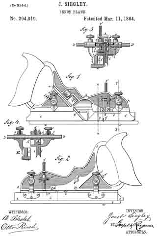
In the accompanying drawings, Figures 1 and 2 are side views, showing both sides of my improved plane. Fig. 3 is a vertical transverse section on line x x, Fig. 1. Fig. 4 is a similar section on line y y of the same figure.

Similar letters of reference indicate corresponding parts.

Referring to the drawings, A represents the stock of my improved bench-plane, which is made of cast-iron or other suitable metal, and provided with a handle of the usual form at the rear end. The middle part of the stock A is provided with an inclined recess, a, in which a cutting tool or plow, B, of any required width is guided and locked in any approved manner, preferably by the means shown in Letters Patent No. 269,968, dated January 2, 1883. Along the lower part of the stock is arranged a fixed blade, C, while a second movable blade, C’, is arranged sidewise of and parallel to the fixed blade C, as will be shown hereinafter. Each of these blades C and C’ contains a laterally-inclined perforation that extends from the upper to the lower part of each blade, so that the lower end of the perforation opens partly at the outer side and partly at the bottom of its respective blade, as shown in Figs. 1 and 8. The advance cutters g and g’ are attached into said perforations by means of set-screws it It in such a manner that the cutting-edge of each cutter projects slightly at the side and lower edge ofthe blades C and C’, thereby providing a better clearance in the work for the plow. The stock A is provided at its front and rear part with openings and sockets A A’, that project at both sides of the same, for the purpose of receiving the guide-rods D and D’, which are made of one continuous piece and of the same thickness throughout, and secured in said sockets by means of set-screws d d’. Larger and smaller guide-rods D D are furnished with each plane, so as to adjust the movable blade C’ at one side and a fence, E, at the other side of the stock, to a greater or smaller distance from the same. On one side of the stock these guide-rods pass through the sleeves r and r’, which are cast in one piece with the blade C’, and secured by means of set-screws s s’. The sleeves and the blade C’ can be adjusted to various distances from the blade C, according to the width of the plow B. At the opposite sides of the stock A the guide-rods D D’ pass through sleeves t t’‘, which are attached to the gage or fence E. The sleeves t t’ are provided with set-screws u u’, for the purpose of laterally adjusting the gage E as the nature of the work may require. A horizontal slot, a2, is cut in the front part of the stock A, for the purpose of receiving the rim of the screw-nut F, which engages the threaded shank F’ of a stop-gage, F2, so as to raise or lower the same on turning the serew-nut F in one or the opposite direction. The shank F’ is guided in suitable holes arranged in the flanged stock A. The stop-gage F2 can thus be adjusted by means of its screw-shank and nut to any desired depth. The blade C’ is also furnished with a stop-gage, f, that is guided in a socket and secured by means of a setscrew, f’. The gage or fence E is provided with a, recess, i, for the stop-gage F2, so as not to interfere with the same, even when the gage E is placed close to the blade C of the stock A.

Having thus described my invention, I claim as new and desire to secure by Letters Patent —

1. In a bench-plane, the combination of the fixed and adjustable blades C C’, each having a laterally-inclined perforation, with advance cutters g g’ and clamp-screws h h’, the advance cutters projecting at their lower ends slightly beyond the outer side plane of the blades C C’, substantially as set forth.

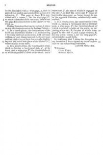
2. In a bench-plane, the combination of the stock A, having a horizontal slot, a2, at its front part, a stop-gage, F2 the threaded shank of which is guided holes of the stock, and a screw-nut, F, the rim of which is engaged by the slot a2, so that the screw-nut F raises or lowers the stop-gage on being turned in one or the opposite direction, substantially as described.

3. In a bench-plane, the combination of the stock A., having a horizontal slot at its front part, a stop-gage, F2, the threaded shank of
which is guided in holes of the stock, an adjusting screw-nut, F, the rim of which is engaged by the slot a2, and a gage or fence, E, having a side recess, i, for the stop-gage F2 substantially as set forth.

In testimony I claim the foregoing as my invention I have signed my name in presence of two subscribing witnesses.

JACOB SIEGLEY.

Witnesses:
CARL KARP,
SIDNEY MANN.

No. 446,194 – Bench Plane (Jacob Siegley) (1891)

[paiddownloads id=”64″]446194


UNITED STATES PATENT OFFICE.

_________________

JACOB SIEGLEY, OF WILKES-BARRE, PENNSYLVANIA.

BENCH-PLANE.

_________________

SPECIFICATON forming part of Letters Patent No. 446,194, dated February 10, 1891.
Application filed May 23, 1890. Serial No. 352,944. (No model.)

_________________

To all whom it may concern:

Be it known that I, JACOB SIEGLEY, of Wilkes-Barre, in the county of Luzerne and State of Pennsylvania, a citizen of the United States, have invented certain new and useful Improvements in Bench-Planes, of which the following is a specidcation.

This invention relates to certain improvements in the bench-plane for which Letters Patent No. 294,919 were granted to me heretofore under date of March 11, 1884, said improvements being designed with a view to simplify the adjustment and the clamping of the cutting tool or bit to the stock and to perrmit the quick and convenient adjustment of the bit.

The invention consists of a bench-plane in which the cutting tool or bit is rigidly fastened to the stock by a clamping-block having transverse steel edges that are pressed against the bit by a thumb-screw acting on the top of the block. The steel block is provided with a longitudinal top groove and guided by said groove on a fixed steel plate attached to the stock, so as to permit the adjustment of the clamping-block by a threaded shank turning in recesses of the stock and by a nut located in an opening of the stock, as will be more fully described hereinafter, and finally pointed out in the claims.

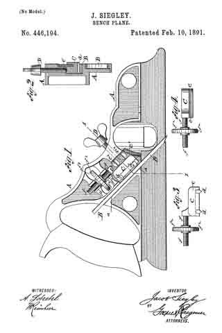
In the accompanying drawings, Figure 1 represents a side elevation of my improved bench-plane. Fig. 2 is a vertical transverse section on the line 1 1, Fig. 1; and Figs. 3 and 4 are respectively a side elevation and a top view of the steel block for clamping the bit of the plane, said block and its adjusting screw-nut being drawn as detached from the stock.

Similar letters of reference indicate corresponding parts.

Referring to the drawings, A represents the stock of my improved bench-plane, which stock is made of cast-iron or other suitable metal, and provided with a handle of the usual form at the rear end. The middle part of the stock is provided with an inclined recess a, in which the cutting tool or bit B is guided and locked in position by means of a steel block C, which is provided in its bottom facing the bit with transverse hardened-steel edges d d, that are pressed firmly against the bit by a wing-screw D, and hold it thereby securely in its place in the stock A. The top of the steel block C is provided with a longitndinal slot e, which is engaged by a steel plate e’, that is attached to the recessed side of the stock A by means of fastening-screws e2. The steel plate e’ serves for holding the steel block in position and guiding it in its up-and-down motion when it is adjusted with the bit. After the bit is adjusted the wing-screw D, which passes through the stock at right angles to the clamping-block C, is tightly applied to the block so as to clamp the same and the bit B firmly to the stock.

The steel block C is provided with a threaded shank f, which is located in recesses f’ of the stock and engaged by a screw-nut f2, having a milled rim, said screw-nut extending transversely through an opening f3 of the stock A and being retained in position therein by the adjacent portions of the stock. On turning the screw-nut f2 in one or the opposite direction the steel block C is moved up or down and carries the bit along so as to adjust the same in proper position in the stock. After the adjustment is made the wing-screw D is tightly applied to the steel block e’, so that the same clamps the bit firmly and securely in position.

My improved fastening and adjusting device for the bit permits the quick adjustment and reliable clamping of the same without necessitating the slotting or recessing of the bit for applying the adjusting device.

Having thus described my invention, I claim as new and desire to secure by Letters Patent —

1. The combination, with the stock, of a bench-plane, said stock having an inclined recess, a cutting tool or bit in said recess, a clamping-block having hardened edges bearing on said bit, and means for adjusting said steel block and bit, substantially as set forth.

2. The combination, with a stock having an inclined recess, of a cutting tool or bit seated in said recess, a clamping-block having hardened edges bearing on said bit, a wing-screw pressing on the top of the block for clamping it to the bit, and means for adjusting said block and bit, substantially as set forth.

3. The combination, with a stock having an inclined recess, of a cutting tool or bit seated in said recess, a clamping-block having hardened edges at the bottom and a longitudinal guide-groove in its top, a steel plate attached to the stock and extending into said top groove, a wing-screw pressing in the top of the block for clamping the same to the bit, and means for adjusting the steel block and bit, substantially as set forth.

4. The combination, with a stock; having an inclined recess, of a cutting tool or bit seated in said recess, a clamping-block having transverse hardened edges at its bottom and a longitudinal groove in its top part, a fixed guide-plate extending into said groove, a threaded shank attached to the clamping-block and set into recesses of the stock, and an adjusting screw-nut engaging said shank and located in an opening of the stock, substantially as set forth.

In testimony that I claim the foregoing as my invention I have signed my name in presence of two subscribing witnesses.

JACOB SIEGLEY.

Witnesses:
HENRY JACKSON,
C. W. KULP.

No. 1,032,956 – Plow Plane (Jacob Siegley) (1912)

[paiddownloads id=”67″]1032956


UNITED STATES PATENT OFFICE.

_________________

JACOB SIEGLEY, OF WILKES-BARRE, PENNSYLVANIA, ASSIGNOR TO STANLEY RULE & LEVEL COMPANY, OF NEW BRITAIN, CONNECTICUT, A CORPORATION OF CONNECTICUT.

PLANE.

_________________

1,032,956. Specification of Letters Patent. Patented July 16, 1912.

Application filed October 18, 1911. Serial No. 655,361.

_________________

To all whom it may concern:

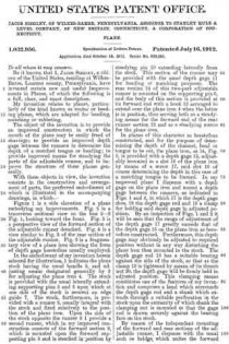
Be it known that I, JACOB SIEGLEY. a citizen of the United States, residing at Wilkes-Barre, Luzerne county, Pennsylvania, have invented certain new and useful Improvements in Planes, of which the following is a full, clear, and exact description.

My invention relates to planes, particularly of the kind known as router or beading planes, which are adapted for beading, matching or rabbeting.

The object of the invention is to provide an improved construction in which the mouth of the planemay be easily freed of shavings; to provide an improved depth gage between the runners to determine the depth of a matched tongue or beading ; to provide improved means for steadying the parts of the adjustable runner, and to improve the structure of these planes generally.

With these objects in view, the invention consists in the construction and arrangment of parts, the preferred embodiment of which is illustrated in the accompanying drawings, in which —

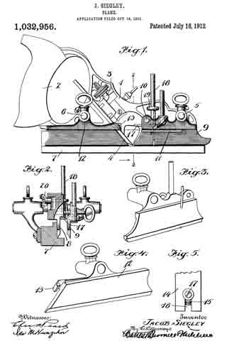
Figure 1 is a side elevation of a plane embodying my improvements. Fig. 2 is a transverse sectional view on the the line 2–2 Fig. 1, looking toward the front. Fig. 3 is a perspective view of the forward section of the adjustable runner detatched. Fig. 4 is a view similar to Fig. 3 of the rear section of the adjustable runner. Fig. 5 is a fragmentary view of a plane iron showing the form of depth gage heretofore usually employed.

In the embodiment of my invention herein selected for illustration, 1 indicates the plane stock having the usual handle 2, and adjusting means designated generally by 3 for adjusting the plane iron 4. The stock is provided with the usual laterally extending supporting pins 5 and 6 upon which at one side of the stock is secured an edge guide 7. The stock, furthermore, is provided with a runner 8, usually integral with the stock and fixed relatively to the position of the plane iron. Upon the side of the stock opposite the runner 8 I provide a second runner, which in my improved construction consists of the forward section 9, which is mounted upon the forward supporting pin 5 and is steadied in position by steadying pin 10 extending laterally from the stock. This section of the runner may be provided with the usual depth gage 11 for beading or matching purposes. The rear section 12 of this two-part adjustable runner is mounted on the supporting pin 6, and the body of this section is provided at its forward end with a hook 13 arranged to extend over the plane iron 4 when the latter is in position, thus serving both as a steadying means for the forward end of the rear runner section 12 and as a steadying means for the plane iron.

In planes of this character as heretofore constructed, and for the purposes of determining the depth of the channel, bead or tongue to be cut, the plane iron, as 14, Fig. 5, is provided with a depth gage 15, adjustably mounted in a slot 16 of the plane iron by means of a screw 17, said slot 16 of course determining the depth in this case of a matching tongue to be formed. In my improved plane I dispense with a depth gage on the plane iron and mount a depth gage between the runners, as indicated in Figs. 1 and 2, in which 17 is the depth gage shoe, 18 the depth gage rod and 19 a clamp for holding said depth gage in adjusted position. By an inspection of Figs. 1 and 2 it will be seen that the range of adjustment of the depth gage 17 greatly exceeds that of the depth gage 15 on the plane iron as heretofore constructed. Furthermore, this depth gage may obviously be adjusted to required position without in any way disturbing the plane iron then mounted in the stock. The depth gage rod 18 has a suitable bearing against the side of the stock, so that as the clamp 19 is tightened by means of its thumb nut 20, the depth gage will be firmly held in adjusted position. This clamping means constitutes one of the features of my invention and comprises a head which surrounds the depth gage rod and a shank which extends through a suitable perforation in the stock upon the extremity of which shank the clamping nut is mounted so that the gage rod is drawn securely against the bearing face on the stock.

By reason of the independent mounting of the forward and rear sections of the adjustable runner, I dispense with the usual arch or bridge which unites the forward and rear portions of the adjustable runners now in use, so that the mouth of the plane is left entirely free for egress of shavings, whereby the plane iron is less likely to become clogged.

While I have herein described a particular embodiment of my invention, it is to be understood that the same may be altered in detail and relative arrangement of parts within the scope of the appended claims.

What I claim is:

1. In a bench plane, the combination with a stock having a fixed runner, of an adjustable runner spaced therefrom, a plane iron between said runners, means for attaching said adjustable runner to the stock, and means for simultaneously steadying said adjustable runner and said plane iron.

2. In a bench plane, the combination with a stock having a fixed runner, of an adjustable runner comprising a forward section, means for attaching said forward section to the stock, means for steadying said forward section in position, a rear section, means for mounting said section upon the stock, a plane iron supported between said fixed and adjustable runners and means for simultaneously steadying said rear section and the plane iron.

3. In a bench plane, the combination with a stock having a fixed runner, of an adjustable runner spaced laterally therefrom and comprising two separate sections independently and adjustably carried by said stock, and a depth gage extending between said fixed runner and the said adjustable runner.

4. In a bench plane, the combination with a stock having a fixed runner, of an adjustable runner comprising a forward section mounted on said gage stock and an independent rear section also mounted on said stock, said rear section having a hook at its forward end adapted to overlie and steady the plane iron at the same time to steady said rear section in operative position.

5. In a bench plane, the combination with a stock having a fixed runner, of a second runner comprising a plurality of independent aligned sections spaced laterally of said fixed runner, means for adjustably supporting said sections from the stock, and means independent of said supporting means for steadying each of said sections in position.

6. In a bench plane, the combination with a stock having a fixed runner, of a second runner spaced laterally therefrom and comprising independent forward and rear sections having their adjacent ends spaced apart to form a free and unobstructed plane mouth, means for adjustably supporting said sections laterally from the stock, and means independent of said supporting means for separately steadying each of said sections in position.

JACOB SIEGLEY.

Witnesses:
JOHN P. POLLOCK,
J.L. CAREY.

_________________

Copies of this patent may be obtained for five cents each, by addressing the “Commissioner of Patents, Washington, D. C.”
_________________