No. 526,154 – Plane-Iron (William F. Kellett) (1894)
UNITED STATES PATENT OFFICE.
_________________
WILLIAM F. KELLETT, OF CHICAGO, ILLINOIS.
PLANE-IRON.
_________________
SPECIFICATION forming part of Letters Patent No. 526,154, dated September 18, 1894.
Application filed June 12, 1893. Serial No. 477,383. (No model.)
_________________
To all whom it may concern:
Be it known that I, WILLIAM F. KELLETT, a citizen of the United States, residing at Chicago, in the county of Cook and State of Illinois, have invented certain new and useful Improvements in Plane-Irons; and I do declare the following to be a full, clear, and exact description of the invention, such as will enable others skilled in the art to which it appertains to make and use the same, reference being had to the accompanying drawings, and to the letters of reference marked thereon, which form a part of this specification.
The invention relates to that class of plane irons in which the cutter or blade is quite thin and is supported by a separate, rigid back plate.
The invention has for its object the improvement of the cap piece so as to more securely hold the blade and prevent its vibrations.
It consists in the use of a cap having a transverse rib between its edge and the main screw, the cap being rigid between the rib and the screw and elastically flexible below the rib and being so formed that when applied it must be depressed by the action of the wedge, ordinarily used in securing plane-irons, before the rib comes into contact with the blade.
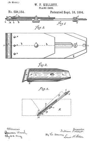
In the accompanying drawings, Figure 1, is a longitudinal section of the plane iron on the line 1–1 of Fig. 2. Fig. 2, is a plan view of the iron. Fig. 3, is a perspective of the cap. Fig. 4 is a sectional view on the line 1–1 of Fig. 2, with the outline of the body of the plane in dotted lines.
The blade is shown at A. It is of finely tempered steel and is quite thin so that in sharpening there is no superfluous metal to cut away. This blade rests upon a back plate B, of softer metal but of greater thickness so as to be quite rigid. The back plate reaches approximately to the cutting end of the blade, and preferably has a slight rib as shown at h, across its end for contact with the blade so that the latter does not rest flatly against the surface of the back plate, the space between the two being so slight, however, that in drawing them together by means of the binding screw the flexure of the blade is scarcely perceptible. This feature is not new in this application.
The cap consists of a rigid body portion b, falling short of reaching the cutting edge of the blade A, by approximately one-half inch, and a flexible extension piece a, secured firmly to the under side and at the lower end of the body portion by the rivets e, and reaching approximately to the end of the blade. This cap extension is bowed outwardly from the end of the body portion, its lower edge being curved downwardly so as to cross the plane of its upper end. The body portion, b, of the cap is provided with the ordinary screw threaded aperture, c’, within which is set the main screw, c, which extends through longitudinal slots in the blade A, and back plate B, its head binding against the under surface of the back plate B, so as to draw the cap down upon the blade A, interposed between the cap and the backing piece. When the three members are first brought together the cap touches the blade only at its extreme ends. The main screw is turned up so as to draw them firmly together but not sufficiently to bring the rib, d, into contact with the blade. When the iron is adjusted to the plane H and the wedge K driven to its place the cap is still further depressed so as to bring the rib d, firmly against the blade A. It is important that the cap bear firmly against the lower end of the blade. This is certainly attained only by depending upon the wedge K to depress the cap at the rib, for were the main screw to be relied upon for this purpose there would be danger of bowing the cap downwardly between the rib and the screw, thereby causing its lower end to tilt upwardly, at least to relieve the pressure of the flexible end upon the blade. Heretofore it has been usual to secure a blade of this character by a cap having no bearing between the main screw and its edge. The result has been that the blade has, particularly when used on hard wood, bowed upwardly from the back plate; that is, the end of the back plate has served as a fulcrum upon which it has turned. The stiffness and elasticity of the blade have brought it back quickly to its normal form, and as a result of the conflicting action — the pressure at the edge tending to bow the blade, its stiffness and elasticity tending to preserve its original form — the blade has been caused to vibrate rapidly, to the manifest detriment of the tool.
By the construction herein shown and described an unyielding, intermediate point, or line of bearing, is secured at d, sufficiently removed from the edge of the blade to wholly counteract this tendency, and a cap is provided which under all conditions holds the blade immovably to its seat upon the back plate. At fand f’, are shown a bolt and nut for securing the upper end of the blade to the back plate in the usual manner.
While I show and describe the cap as of two pieces secured together it is obvious that it may be of a single piece provided it meet the conditions of having a firm transverse rib between its edge and the main screw, and is substantially inflexible between this rib and the main screw, and flexible and elastic below the rib, and has its flexible portion curved so that its edge falls below the rib, thereby insuring a close joint between the edge of the cap and the blade.
I am aware that it is known to secure a bearing above the edge of the cap by the use of a supplemental flexible cap interposed between the rigid cap and the blade, but such construction does not meet the requirement for a firm bearing upon the blade to prevent its vibration.
I claim as my invention —
l. In a plane iron, the combination with a thin cutting blade, A, of a rigid back plate, B, for supporting the blade, and a cap for covering the blade, such cap comprising a rigid portion, b, having bearings at its upper and lower ends upon the blade, and a flexible extension, a, adapted to bear upon the blade contiguous to its cutting edge, substantially as described and forthe purpose specified.
2. The combination in a plane iron, with a thin cutting blade and a rigid back plate for carrying the same, of a cap piece comprising a rigid portion b, and an elastic extension piece a, secured to the under side of the lower end of the portion b; and being bowed outwardly, its extreme end normally crossing the plane of its inner or attached end, and being adapted to bear against the blade contiguous to its cutting edge, substantially as described and for the purpose specified.
3. The combination in a plane iron, with a thin cutting blade and ia rigid back plate for carrying the same, of a cap piece having a transverse rib and being elastic below this rib and rigid above it and being so curved that when applied to the blade the rib does not touch the blade until the cap is compressed, substantially as described and for the purpose specified.
4. In a plane iron, the combination of a rigid back plate, a flexible cutting blade carried by the back plate, and a cap piece having its lower end flexible and its upper portion rigid and having a transverse rib at the juncture of the flexible and rigid portions and being adapted to bear upon the blade, whereby positive contact is insured between the blade and the back plate directly below the rib when tl1e iron is adjusted to the plane, substantially as described and for the purpose specified.
In testimony whereof I affix my signaturein presence of two witnesses.
WILLIAM F. KELLETT.
Witnesses:
T. A. KELLETT,
SAMUEL LEGER.