No. 310,473 – Bench-Plane (William Steers) (1885)
UNITED STATES PATENT OFFICE.
_________________
WILLIAM STEERS, OF BRATTLEBOROUGH, VERMONT.
BENCH-PLANE.
_________________
SPECIFICATION forming part of Letters Patent No. 310,473, dated January 6, 1885.
Application filed October 27, 1884. (No model.)
_________________
To all whom it may concern:
Be it known that I, WILLIAM STEERS, a citizen of the United States, residing at Brattleborongh, in the county of Windham and State of Vermont, have invented a new and useful Improvement in Bench-Planes, of which the following is a specification, reference being had to the accompanying drawings.
This invention relates to improvements in bench-planes, which will be hereinafter more fully described, and pointed out in the claim.
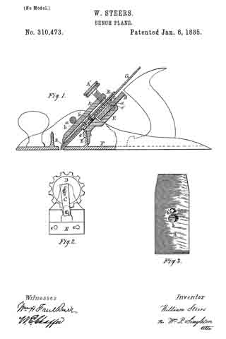
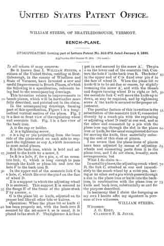
In the accompanying drawings, forming part of this specification, Figure I is a longitudinal vertical section of the plane. Fig. 2 is a face or front view of the regulating-wheel and eccentric link. Fig. 3 is a face view of the back-iron.
A is the cap or holder.
A’ is a tightening-screw.
a is a lug or pin projecting from the inner side of the plane-stock on each side to support the tightener or cap A which is common to most metal planes.
B is the back-iron, which is held and adjusted to the knife by a screw, b.
In B is a hole, b’, for a pin, c, of an eccentric link, C, which is long enough to pass through the knife or plane~bit and into the hole b’ in the back-iron B.
In the upper end of the eccentric link C is a hole, c’, which fits over the pin d on the face of wheel D.
E is a support in which the adjusting-wheel D is centered. This support E is secured to the flange E’ of the frame of the plane-stock F by a screw, e.
G is the plane bit or knife, adjusted on its proper bed like all other bits or knives.
Operation: When the plane bit or knife G has been properly set, with the back-iron B secured by the set–screw b, as is usual, it is placed in the stock F. The tightener A is then put in and secured by the screw A’. The pin c on the lower end of the eccentric link C enters the hole b’ in the back-iron B. The hole c’ in the upper end of C is fixed over pin d in the face of wheel D. When the plane bit or knife G is to be set fine or coarse, by slightly loosening the screw A’, and with the thumb and fingers turning wheel D to right or left, the eccentric link C will move the knife up or down, as may be required, and by tightening screw A’ the knife is secured to the proper adjustment.
The peculiar feature of this invention is the substitution of the eccentric link C, connected directly by a crank-pin with the regulating or adjusting wheel D itself at one end, and at the other end connected by a pin with the plane-iron cap through the slot in the plane iron or knife, for the usual complicated devices for moving the knife, thus materially reducing the cost of this class of planes.
I am aware that the plane-irons of planes have been adjusted by means of adjusting wheels and connecting parts from it to the plane-iron, and I do not claim, broadly, such arrangements; but
What I do claim is —
In metallic planes, the adjusting crank-wheel D, the link C, attached at one end immediately to the crank-wheel by a wrist-pin, having at its other end a pin which passes through a slot in the plane iron or knife into the back-iron, in combination with the plane iron or knife and back-iron, substantially as and for the purpose described.
In testimony that I claim the foregoing as my own I hereto affix my signature in presence of two witnesses.
WILLIAM STEERS.
Witnesses:
J. G. EDDY,
CLARENCE F. R. JENNE.