No. 20,615 – Device For Adjusting Plane Irons (Leonard Bailey) (1858)

[paiddownloads id=”76″]20615


UNITED STATES PATENT OFFICE.

_________________

L. BAILEY, OF WINCHESTER, MASSACHUSETTS.

DEVICE FOR ADJUSTING- PLANE-IRONS.

_________________

Specification of Letters Patent No. 20,615, dated June 22, 1858.

_________________

To all whom it may concern:

Be it known that I, LEONARD BAILEY, of Winchester, in the county of Middlesex and State of Massachusetts, have invented a new and useful Improvement in Joiners’ Planes; and I do hereby declare that the same is fully described and represented in the following specification and the accompanying drawings, of which —

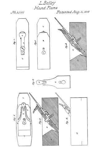
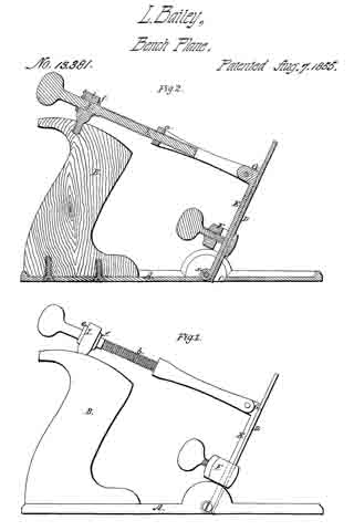
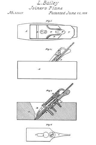
Figure 1, is a top view. Fig. 2, a side elevation; and Fig. 3, a vertical, central and longitudinal section of a plane having my improvement. Fig. 4, is a top view of the friction plate and its adjuster.

The nature of my invention consists in the application of a movable friction plate and a device for adjusting or moving it to the rear side of the throat of a plane stock, and so as to support the plane iron or cutter and be a means by which it may be set or adjusted with respect to the bearing or bottom of the plane stock.

In the drawings, A, denotes the stock of which B, is the throat; C, the plane iron, the latter with its cap iron D, being held in place by a lever E, a thumb cam F, and a bearer or screw, G.

The bearer extends upward from the rear side of the throat and through slots made in the plane iron, the cap iron and the lever and its head serves as a fulcrum to the lever. A spring, H, projecting from the lever as shown in the drawings, serves to separate the thumb cam from the cap in a manner to prevent the former from being turned by the latter while it is being moved longitudinally with the plane iron.

I, is a metallic plate, which is placed fiat against the rear face a, of the throat, B, and serves to support the plane iron. This plate I, is formed with a slot, b, and a circular opening, c, the latter being for the reception of an eccentric, d, projecting from a lever, e, which turns on a fulcrum or screw, f, arranged as shown in the drawings. By turning the lever on its fulcrum in one direction the friction plate, will be raised upward in the throat. So by turning the lever in the opposite way, the plate will be depressed, the amount of movement of the friction plate depending on that of the lever. As the plane iron or cutter rests directly on and is forced down upon the friction plate, it will be moved by and with the latter and so that its cutting edge may be adjusted with great nicety with respect to its distance from or beyond the supporting face or bottom surface of the stock.

The lever, e, the eccentric, d, and the opening c, I term the adjuster, as when applied to the stock and plate, I, as described, they constitute a means of adjusting the plane iron as explained. Were the adjuster applied directly to the plane iron as it is to the friction plate, that is were we to dispense with the friction plate and insert the eccentric of the adjuster in a circular orifice made in the plane iron, it will be readily seen that but very little wear of the plane iron, such as must necessarily take place in sharpening it, or in other words, a reduction of its length, a distance equal to the eccentricity of the eccentric, would render the iron useless. By having a friction plate independent of the plane iron, the extent of grinding or reduction of the plane iron is not limited to the amount of eccentricity of the eccentric, but may be carried on to a much greater extent. Thus, the advantages of my invention will be apparent. It can be applied to most ordinary plane stocks without alteration of the plane iron, or any addition thereto, and it enables the plane iron to be adjusted with great nicety, without requiring the fastening contrivance to be first loosened.

I claim —

The combination of the movable friction plate, I, (separate from the plane iron, C,) and its adjuster or the equivalent of the latter with the throat of the plane stock and to operate the plane iron substantially as specified.
In testimony whereof, I have hereunto set my signature.

LEONARD BAILEY.

Witnesses:
R. N. EDDY,
F. P. HALE, Jr.

No. 20,855 – Spoke Shave (Leonard Bailey) (1858)

[paiddownloads id=”77″]20855


UNITED STATES PATENT OFFICE.

_________________

L. BAILEY, OF WINCHESTER, MASSACHUSETTS.

SPOKE-SHAVE.

_________________

Specification of Letters Patent No. 20,855, dated july 13, 1858.

_________________

To all whom it may concern:

Be it known that I, LEONARD BAILEY, of Winchester, in the county of Middlesex and State of Massachusetts, have invented an Improved Spoke-Shave; and I do hereby declare that the same is fully described and represented in the following specification and the accompanying drawings, of which —

Figure 1, is a top view. Fig. 2, a bottom or underside view, and Fig. 3, a vertical central and transverse section of it. Fig. 4, is a. longitudinal section taken through the retracting spring and its protecting cavity or chamber. Fig. 5, is a top view of the stock without its appliances. Fig. 6, is an end view of the spoke shave.

The nature of my invention consists in an improved spoke shave constructed with its bearing surface in front of its cutter applied to the stock by means of a lever having an adjusting screw or its equivalent or an adjusting screw and a retracting spring so applied to it as to enable the said bearing surface to be moved either toward or away from the cutting edge of the cutter in order to diminish or enlarge the chip passage as well as to vary the angular position of the said bearing surface with respect to that in rear of the cutter, whereby advantages in the operation of the instrument are attained. Also, in an application and arrangement of a protecting cavity or chamber with respect to the lever and its retracting spring.

In the drawing A, denotes the body or the stock of the spoke shave, as constructed with two handles, a, a, and a throat or recess, B, for the reception of a cutter or plane iron B’, which is arranged on the seat or bottom of the throat and is confined thereto by means of a screw, c, which passes through a slot, d, formed in the iron and screws into the stock. The head of the screw laps over the edges of the slot.

The bearing surface of the stock is composed, not only of a stationary part, d’, in rear of the cutter B’, but a movable part, e, which is arranged in front of the cutter. This movable part is made on a lever C, which is shaped as shown in the drawings, and has a journal extending from each side of it, into the adjacent side of the throat such journal being shown in dotted lines in Fig. 1. Furthermore an adjusting screw, E, screws through the back part of the lever and against the seat of the throat of the stock or such screw may pass through the lever and screw into the stock and be so applied to the lever or have such shoulders or appliances that when the screw is turned in one direction it shall tilt the rear part of the lever one way or toward the stock, and when moved in the opposite direction produce a reverse movement of the said lever.

I prefer that the adjusting screw on one side of the journal should screw through the lever and against the seat and that the part of the lever which is on the opposite side of the journals should be provided with a retracting spring I, to be fastened to it and bear on the stock. Were this spring fastened at its middle to the top of the lever and made to extend across the same in such manner as to have its ends bear on the stock, the spring would be so exposed to shavings, as they might be expelled from the throat, that they would be liable to collect between it and the lever and by so doing effect, more or less, its correct action. In order to prevent this I form within and traversely through the lever, a cavity or chamber, g, which I make of a less diameter at its middle part, than it is at its ends or as shown in Fig. 4. This cavity or chamber receives the spring I, made of a piece of round steel wire, and to fit tightly at its middle part to the middle part of the cavity while the ends of the said spring rest on the stock as shown in Figs. 1 and 6. By means of the chamber or cavity surrounding the spring, the latter is protected from shavings which during the use of the shave might rise out of the throat and get between the spring and the lever were the spring not so protected.

By means of the above described mode of changing the width of the mouth of the shave, the thickness of its cut or of the shaving made by it when in use may be regulated, a spoke shave so made being found to operate in practice to great advantage.

I claim —

1. The improved spoke shave as constructed with its bearing surface in front of its cutter, applied to the stock by means of a lever having an adjusting screw or its equivalent, or a screw and a spring applied to it so as to enable the said bearing surface to be moved with respect to the cutter, and the bearing surface in rear thereof, substantially in manner as described.

2. I also claim the arrangement and application of a projecting cavity or chamber within the lever and to the spring thereof in manner and for the purpose as hereinbefore set forth.

In testimony whereof I have hereunto set my signature.

LEONARD BAILEY

Witnesses:
R. H. EDDY,
F. P. HALE, Jr.

No. 21,311 – Securing Plane Irons To The Stocks Of Bench Planes (Leonard Bailey) (1858)

[paiddownloads id=”79″]21311


UNITED STATES PATENT OFFICE.

_________________

LEONARD BAILEY, OF WINCHESTER, MASSACHUSETTS.

METHOD OF SECURING PLANE-IRONS TO THE STOCKS OF BENCH-PLANES.

_________________

Specification of Letters Patent No. 20,311, dated August 31, 1858.

_________________

To all whom it may concern:

Be it known that I, LEONARD BAILEY, of Winchester, in the county of Middlesex and State of Massachusetts, have invented a new and useful Improvement in Hand-Planes; and I do hereby declare that the same is fully described and represented in the following speciiication and the accompanying drawings, of which —

Figure 1 denotes a top view of a smoothing plane having my invention applied to it; Fig. 2, a side elevation of it, while Fig. 3 is a central, vertical and longitudinal section of it. Fig. 4 is an underside view of the plane iron and its cap, Fig. 5 being a top view of the same. Fig. 6 is a view of the clamp lever and thumb cam thereof to be hereinafter described.

The object of my invention is to provide the plane with a ready means of fixing the plane iron or cutter in the stock or of removing the same therefrom as well as of adjusting the plane iron in the stock as circumstances may require.

In the drawings, A, exhibits the plane stock furnished with a throat, B, for the reception of the cutter or plane-iron, C, or the same and its cap iron, D. In the above mentioned drawings the cap iron, D, is exhibited as confined to the plane iron or cutter, C, by means of a screw h, extending upward from the underside of the cutter C, and through a long slot, b, formed in the said cutter as shown in Figs. 3 and 4. The bearing surface of the throat or that marked d, d, in Fig. 3, is furnished with a recess, e, for the reception of the head of the screw, h, by which the cap iron is confined to the plane iron, such recess being made of a sufficient size or diameter to allow the necessary longitudinal movements of the plane iron. Furthermore, the cap-iron as shown in the drawing, is made with a hole, f, arranged midway between its two edges and directly over the slot in the plane iron, such hole being to enable the plane iron and its cap to be passed over the head of a bearer or screw F, inserted in the plane stock and made to project from the bearing surface d, d, as shown in Fig. 3. In connection with this screw or bearer, F, a clamp lever or plate, G, is employed, it being formed as represented in the drawings and hinged or jointed at its upper end to a thumb cam, H. Moreover, the clamp lever, G, has an elongated slot, s, made through it, the said slot in one half its length being circular in form and having a diameter or width somewhat larger than the head of the bearer or screw, F, while the remainder of the slot is constructed of a width or diameter less than that of the head of the screw and sufficient to receive the shank of the screw the whole being as shown in the drawings. In consequence of the slot being so made we are enabled to slip or pass the clamp lever, G, over the head of the screw and to press the said clamp lever, G, downward in such manner as to cause the head of the bearer or screw to project beyond the sides of the slot, and constitute a fulcrum for the clamp plate when the thumb cam is turned down into the position as shown in Figs. 1 and 2. By turning the thumb cam down, we clamp or confine the plane iron in the stock, but by turning such thumb cam upward so as to bring it into the position as represented in Fig. 7 (which is another longitudinal section of the plane) we loosen the clamp lever from the bearer in such manner as to enable us either to remove it therefrom or to adjust the plane iron as circumstances may require. By turning backward the thumb cam, it will be made to so operate against the plane iron or the cap thereon as to raise the upper end of the clamp lever and force the lower end against the bearer in such manner as to cause the lower end of the clamp plate to be pressed downward upon the plane iron and secure such iron firmly upon its bearing surface, d, d. Thus it will be seen that by means of the bearer, the clamp lever and the thumb cam the plane iron may be secured in place in the throat of the plane stock or released therefrom with great facility or expedition.

By making the shank of the bearer to screw into the stock we cause the bearer to be adjustable with reference to the seat of the plane iron, and therefore we have a means of readily adapting the bearer to a plane iron of any ordinary thickness, whether provided or not with a cap iron, the adjustment of the bearer being for the purpose of causing the thumb cam and the clamp lever to be brought into the proper situations to enable them by their conjoint action as described to fasten the plane iron to the stock. If desirable, there may be two bearers, F, but I prefer to have but one, as such is quite suflicient. These bearers may be arranged near the edges and may project either from or into the stock. A single bearer, however, arranged in the middle of the seat of the plane iron and either made stationary or adjustable with respect to such seat is far preferable to more than one. Furthermore by the employment of one bearer and its arrangement at the middle of the plane iron and the clamp lever as described the lower bearing edge of the clamp lever is left free to perfectly or so perfectly adjust itself to the plane iron or the cap iron thereof as to bear thereon throughout the entire length of the edge.

I claim —

The application and arrangement of one or more bearers, F, the clamp lever, G, and the thumb cam, H, together and with respect to the top surface of the plane iron and the bearing surface or cutter seat, d, d, of the throat substantially as represented and described.

LEONARD BAILEY.

Witnesses:
R. H. EDDY,
F. P. HALE, Jr.

No. 13,381 – Plane Scraper (Leonard Bailey) (1855)

[paiddownloads id=”24″]13957


UNITED STATES PATENT OFFICE.

_________________

LEONARD BAILEY, OF WINCHESTER, MASSACHUSETTS.

PLANE-SCRAPER.

_________________

Specification of Letters Patent No. 13,381, dated August 7, 1855.

_________________

To all whom it may concern:

Be it known that I, LEONARD BAILEY, of Winchester, in the county of Middlesex and State of Massachusetts, have invented an Improved Plane-Scraper; and I do hereby declare that the same is fully described and represented in the following specification and the accompanying drawings, letters, figures, and references thereof.

Of such drawings, Figure 1, is a side elevation, while Fig. 2, denotes a central vertical and longitudinal section of my improved tool or invention.

In such drawings, A, represents a plane stock or bed which may be constructed of metal and have a handle, B, extended from and above it. The bed is provided with a throat or opening, C, for the scraper or plane cutter D, to pass through, and over this throat and hinged or jointed to the stock (as seen at, x, Fig. 1) so that it may be turned in a direction, either toward or away from the handle, B, is a plate, E, embraced by a screw stirrup or clamp, F, having some equivalent contrivance for fastening the scraper to it.

A forked arm G, is jointed to the upper part of the rear side of the plate, E, and is provided with a female screw, a, for the reception of a male adjusting screw, b, which should be so applied to the top of handle, B, as to be immovable with respect thereto except being rotated in a transverse direction.

For this purpose the rod is provided with a journal, d, extending through a projection, I, having rollers, e, f, arranged on opposite sides of the said projection as seen in the drawings.

The movable plate and its screw clamp may be termed the holder of the scraper or plane iron. By means of the adjusting screw the inclination of the scraper to the lower surface of the bed or stock may be adjusted as occasion may require it often being desirable to accomplish this result in order to prepare the tool for a correct performance of its duty — the same depending on the particular kind or character of the wood on which we may wish to employ it — the specific object of such tool being to scrape or pare down the surface of such wood.

As the turning points of the cutter holder, are arranged a short distance above the bottom surface of the stock (as seen at, x, in Fig. 1) it will be observed that any movement of the holder on such points, will either elevate or depress the lower edge of the cutter scraper. Thus by means of the adjusting screws or mechanism, the fineness of the cut of the scraper may be modified.

The utility and advantage of a scraper or smoothing plane constructed in the above described improved form must be evident to a skilful workman on inspection of it.

I claim —

Combining the scraper or plane cutter with the stock by means of the movable holder and its adjusting mechanism substantially as specified.

In testimony whereof, I have hereunto set my signature this eleventh day of July A. D. 1855.

LEONARD BAILEY.

Witnesses:
R. H. EDDY,
F. P. HALE, Jr.