No. 471,391 – Carpenter’s Plane (Oliver Longval) (1892)

[paiddownloads id=”485″]471391


UNITED STATES PATENT OFFICE.

_________________

OLIVER LONGVAL, OF WORCESTER, MASSACHUSETTS, ASSIGNOR
OF ONE-FOURTH TO FREDERICK C. WALTON, OF SAME PLACE.

CARPENTER’S PLANE.

_________________

SPECIFICATION forming part of Letters Patent No. 471,391, dated March 22, 1892.
Application filed March 2, 1891. Serial No. 383,449. (No model.)

_________________

To all whom it may concern:

Be itknown that I, OLIVER LONGVAL, of the city and county of Worcester, and State of Massachusetts, have invented certain new and useful Improvements in Carpenters’ Planes and I do hereby declare that the following is a full, clear, and exact description thereof, reference being had to the accompanying drawings, forming a part of this specification, and in which —

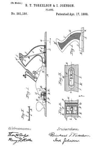
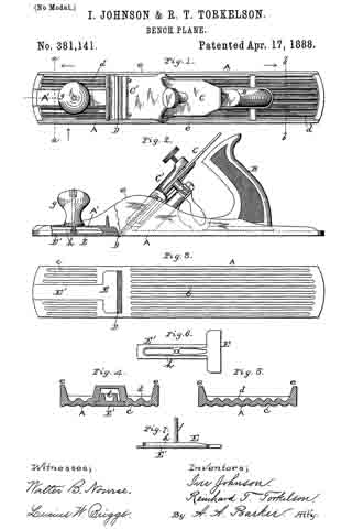
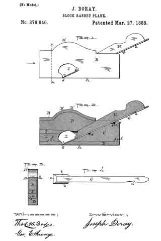
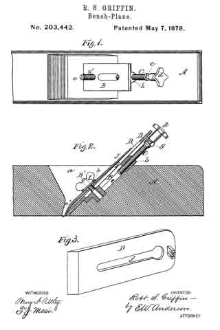
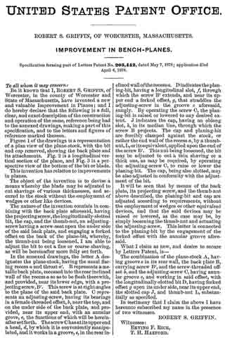
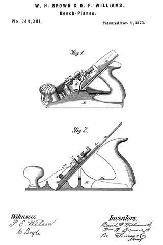
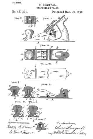
Figure 1 represents a side view of a carpenter’s plane embodying my improvements. Fig. 2 is a horizontal section through the handle, showing a top or plan view of the plane with the knife and the usual holding parts thereof detached to more fully illustrate that part of my improvements coming under the same. Fig. 3 is a bottom view of the plane. Fig. 4. is a vertical longitudinal section through the parts shown in Fig. 2. Figs. 5, 6, and 7 represent different modifications in the construction of the front oiler of the plane, which will be hereinafter more fully described. Fig. 8 is a vertical section of the rear oiler and part of the bed of the plane, taken on line a, Fig. 2; and Fig. 9 is an enlarged horizontal section through part of the plane-bed and one end of said rear oiler, showing the inlet to the oil-chamber and its detachable stopper or plug, taken on line 19, Fig. 1.

With the exception of the oiling devices hereinafter described, the plane is of ordinary construction.

The purpose of my invention is to improve upon the means heretofore employed for oiling the bottom of the plane; and it consists in certain improvements in the construction of said oiling devices foreffecting the above result.

In order that others may better understand the nature and purpose of said improvements, I will now proceed to describe the same more in detail.

In the drawings, A represents the bed, B the front handle, C the rear handle, D the knife or blade, E the knife-holding cap, F the adjusting-screw, and G the lever, of an ordinary plane. The rear oiling device H is preferably located on the bed between the base of handle C and the knife and its supporting parts. It is constructed by forming a transverse rib or projection c on the top of and integral with the bed between the vertical side flanges d d thereof. Within said transverse projection is formed a chamber c’ for holding the oil, which chamber is provided with an opening at one end through which to pour in the oil and with a series of small vertical openings e, through which said oil is discharged to oil the bottom of that portion of the plane coming back of the throat I. The inlet to chamber c’ is provided with a suitable screw or plug f and washer f’ to prevent the oil from passing out at said point, while the small vertical discharge-openings are provided with wood plugs e’, preferably of pine or similar soft porous wood, to properly control the outflow of oil.
Said wood plugs I find in practice permit just sufficient oil to pass out to oil the bottom of the plane properly and without waste of oil, the plane when thus oiled running smooth and easy upon the most objectionable surfaces. The essential feature which I claim as new in this part of my invention is the formation of the oiler integral with the bottom or bed of the plane and providing the chamber with an end opening and plug, so that the chamber may be more conveniently opened from the outside of the plane, as shown, in filling the same.

The use of wood plugs in the discharge-openings I am aware is not new, the same being shown and claimed in the United States Patent to Edward F. Gordon, No. 213,104, dated March 11, 1879, and I therefore make no claim, broadly, thereto.

The front handle B constitutes a part of the oiling device for oiling the front end of the plane, and said device is constructed as follows: A metal base B’, made in the form of an inverted cup, so as to form a chamber B2 between the same and the bed when fitted in position, is provided with a vertical central stem g, projecting up, and over which is fitted the knob or handle B. A downwardly-projecting central screw h is also formed on the base, which is adapted to be screwed into a correspondingly-shaped vertical opening formed in the bed, whereby the base is fastened to said bed. The stem g may be made with a threaded surface, so that the knob B may be screwed on, as shown in Fig. 4, or smooth, so that said knob may be driven on, as shown in Figs. 5 and 6.

The oil is preferably supplied to chamber B2 through an opening formed vertically through the stem g and connecting with said chamber through suitable openings at each side of the screw h, as is shown in Figs. 4 and 5. I do not limit myself, however, to forming the oil-inlet in the stem g as aforesaid, as a like result may be effected by means of a plugged inlet, as g’, in the body of base B’, as is shown in Fig. 6.

In case a wood knob or handle B is used, it is preferable to employ an internally-threaded tube i in the opening which receives the stem g to produce a more durable construction, as is shown in Fig. 7.

In the constructions shown in Figs. 4 and 7 the handle or knob serves as the stopper for preventing the oil from passing out through the supply-opening, while in Fig. 5 a screw-plug or nut j is employed for that purpose, a screw being formed on the plug, which may be screwed into the oil-inlet, which is threaded at its upper end for the purpose. In Fig. 6 a reverse construction is adopted, a threaded opening being formed in the plug to receive a screw formed at the upper or outer end of the stem; but said stem does not in this instance serve as an oil-passage, the nut j being used for holding the knob B in place. In each case an elastic or other suitable washer k is preferably used at the oil-inlet under the knob or plug to make the same oil-tight, and a suitable washer l is also used for the same purpose between the base B’ and bed A. In like manner to the other oiler, a series of vertical discharge-openings are formed in said bed for the front oiler last described, formed within the circumference of the bearing-point of the base against the bed, which openings are also provided with wood plugs e’, as in the former instance.

My improvement in the front oiling device consists in the combination of the separate and detachable knob B and base B’ and the special construction adopted in connection therewith and the plane-bed for effecting the desired result.

I am aware of the United States Patents to W. Wood, No. 191,393, dated May 29, 1877, and 471,391 to L. A. Dearth, No. 363,213, dated May 17, 1887, both for planes, and I make no claim to the constructions therein set forth and shown.

What I claim as new, and desire to secure by Letters Patent, is —

1. In a carpenter’s plane, the bed having a transverse chamber c’ formed therein open at the end having a series of vertical openings or outlets through the bed to the bottom of the plane, in combination with a suitable plug or stopper having a washer under the same for closing the aforesaid end opening and wood plugs for closing the vertical openings, while at the same time permitting a certain quantity of oil to discharge through the latter, substantially as and for the purpose set forth.

2. In a carpenter’s plane, the bed having a series of vertical openings in its front end filled with wood plugs, as described, in combination with the base B’, made cup-shaped to form an oil-tight chamber between the same and the bed when fitted thereto, with a washer between it and said bed, also having a downwardly-projecting screw part for securing said base to the bed and an upwardly-projecting stem fitting in a knob or handle B, said knob or handle, and means for supplying oil to the chamber in the base, as well as for closing the supply-opening thereto oil-tight, substantially as and for the purpose set forth.

3. In a carpenter’s plane, the bed having a series of vertical openings in its front end filled with wood plugs, as described, in combination with the base B’, made cup~shaped to form an oil-tight chamber between the same and the bed when fitted thereto, with a washer between it and said bed, also having a downwardly-projecting screw part for securing said base to the bed and an upwardly-projecting stem having a threaded tube or sleeve over the same, as well as having a vertical opening therein connected with the chamber in base B’ and fitting in the knob or handle B, said knob or handle, and a washer interposed between the same and the end of the stem, substantially as and for the purpose set forth.

OLIVER LONGVAL.

Witnesses:
ALBERT A. BARKER,
W. B. NOURSE.

No. 406,605 – Carpenter’s Plane (Reinhard T. Torkelson) (1889)

[paiddownloads id=”451″]406605


UNITED STATES PATENT OFFICE.

_________________

REINHARD T. TORKELSON, OF WORCESTER, MASSACHUSETTS,
ASSIGNOR TO IVER JOHNSON, OF SAME PLACE.

CARPENTER’S PLANE.

_________________

SPECIFICATION forming part of Letters Patent No. 406,605, dated July 9, 1889.
Application filed November 23, 1888. Serial No. 291,675. (No model.)

_________________

To all whom it may concern:

Be it known that I, REINHARD T. TORKELSON, a citizen of the United States, and a resident of the city and county of Worcester, State of Massachusetts, have invented certain new and useful Improvements in Carpenters’ Planes; and I do hereby declare that the following is a full, clear, and exact description thereof, reference being had to the accompanying drawings, forming a part of this specification, and in which —

Figure 1 represents a side view, partly in section, of a bench-plane embodying my improvements. Fig. 2 is a plan of the lower part of the cutter with my improved cap secured thereon, as hereinafter more fully described. Figs. 3 and 4 are transverse sections through said cutter and cap, taken on lines a and b in Fig. 2, respectively, looking in the direction of the arrow in said figure. Fig. 5 is a central longitudinal section through the cutter and cap, taken on line c, Fig. 2; and Fig. 6 is a perspective view of the detachable angle-plate employed for adjustably fastening the cap to the cutter, as hereinafter specified.

To enable those skilled in the art to which my invention appertains to better understand the nature and purpose thereof, I will now proceed to describe it more in detail.

My said invention relates to improvements upon the carpenter’s plane patented by O. R. Chaplin in the United States under date of May 7, 1872, No. 126,519; and it consists of improvements in the construction of the cutter and cap, as hereinafter set forth.

In the drawings, the part A represents the plane-stock; B, its handle; C, its knob for holding the front end of the plane; D, the cutter; E, the cap; F, the supporting-saddle, fastened at its lower end to the boss G, projecting up and backfrom the bottom of the stock.

H is the clamp, having the lugs d upon each side adapted to catch under the sides of the saddle.

I is the thumb-screw for operating said clamp.

J is a screw-cam fitted to turn on the stationary pin e.

K is a half-nut projecting down from the upper end of the saddle and engaging with said screw-cam, and L is a lever for operating through the screw-cam and half-nut the saddle and cutter longitudinally.

Any further description of the old parts of the plane may be obtained, if desired, by reference to the patent previously alluded to.

My improvements in the cutter and cap are as follows: Instead of fastening the cap E to the clamp H, as in said Chaplin patent, it is in this instance fastened to the cutter D by forming a transverse opening f in said cutter to receive a transverse angle-plate M, which is passed up through the cutter from the under side, so as to form a holding-loop above the cutter. Through said loop is passed the longitudinal tongue or blade g, formed on the cap E, whereby said cap is held in position. The tongue or blade is made curving or bow-shaped lengthwise, so as to produce a constant pressure upward against the holding angle-plate when it is slipped under the same, and the cap is also provided with two flanges h h, one at each side of the tongue or blade, curved downward, and bearing at their ends upon the top surface of the cutter, the purpose of the latter being to hold the edge j of the cap elevated above the cutter to prevent injury to the cutting-edge of said cutter in the operation of placing the cap in position thereon. Although said flanges h h are preferable for the above purpose, I do not limit myself thereto, as the same result may be obtained by forming the cap so as to bear upon the cutter in a similar manner at any suitable point between the sides or edges thereof, said modification consisting simply in changing the positions of said bearing-points. The same will be readily understood without special illustration in the drawings. The angle-plate is held in position in the cutter against the upward pressure produced by the spring tongue or blade g by means of ears or projections k k, formed upon each end thereof, adapted to bear upon and hold against the under side of the cutter. Said ears are preferably recessed into said cutter, as is shown in Fig. 4, so as to bring the bottoms of said plate and cutter flush with each other. It is also preferable to make the edges of the ears slightly beveled or inclined and the ends of the opening in the cutter correspondingly beveled, as is indicated at l l in Figs. 4 and 6, for the purpose of holding the angle-plate in the cutter after having been sprung into position therein when the cap is not fitted thereto. In practice only a slight bevel is required to effect the desired result. Consequently the plate may be easily sprung into position, as aforesaid. As so slight a bevel would not be perceptible in illustrating the same, I have shown quite a sharp bevel in the drawings, and considerably greater than would be employed in practice.

In fitting the cap to the cutter the angle-plate is first passed up through the opening in said cutter and forced into position, after which said cap is placed on the cutter and its spring tongue or blade g slipped up through the loop formed by the angle-plate projecting above the surface of the cutter. The cap is then adjusted accurately, as required, to govern the thickness of the shaving to be cut, when the cutter, with the cap thus adjusted and secured thereon, is placed in the plane and clamped in position, as in the Chaplin and other planes, by means of the clamp H and its thumb-screw.

Although my invention is more particularly designed to be used in the manufacture of planes whose stock is made of metal, it is equally applicable to other kinds of planes. By thus securing the cap to the cutter, as hereinbefore described, it will at once be manifest to those skilled in the art to which my invention appertains that said cap, being susceptible of adjustment to the cutter before fitting said cutter in position, renders said operation more easy to perform, and also admits of a more accurate adjustment than when said adjustment is made after the cutter has been placed in position. A construction whereby said result may be accomplished is the main purpose of this invention.

If desired, a holding-loop may be formed upon or secured to the cutter to take the place of the detachable angle-plate M. The construction described, however, is preferable.

What I claim as new, and desire to secure by Letters Patent, is —

1. A combined cutter and cap for carpenters’ planes, comprising, in combination, the cutter having a suitable transverse holding-loop above its top surface and the cap having a longitudinal spring tongue or blade adapted to be passed through said loop to hold the cap in position during and after adjustment upon the cutter preparatory to the application thereof to the plane, substantially as and for the purpose set forth.

2. The combination of the cutter D with the detachable angle-plate M, fitted transversely in a suitable opening therein, and the cap E, having the longitudinal spring tongue or blade g, adapted to be passed through the loop formed by said angle-plate when fitted in position in the cutter, substantially as and for the purpose set forth.

3. The combination of the cutter D with the detachable angle-plate M, fitted transversely in a suitable opening therein, and the cap E, having the supporting side flanges h hand the longitudinal spring tongue or blade g, the latter adapted to be passed through the loop formed by said angle-plate when iitted in position in the cutter, substantially as and for the purpose set forth.

4. In a bench-plane, the combination, with the cutter D, having a transverse opening with beveled sides, of the detachable angle-plate M, having flanges with the edges thereof beveled to correspond with the sides of the opening in the cutter, substantially as and for the purpose set forth.

5. In a bench-plane, the combination, with the cutter D, having a transverse opening with beveled sides, of the detachable angle-plate M, having flanges with the edges thereof beveled ito correspond with the sides of the opening in the cutter and the tongue or blade of cap E, substantially as and for the purpose set forth.

6. The combination of the stock, saddle, and clamp device of a bench-plane with the cutter D, provided with a transverse loop above its top surface, and the cap E, having the supporting-flanges h h, and the tongue or blade g, the latter adapted to be passed through said loop to hold the cap upon the cutter during and after adjustment preparatory to the application thereof to the plane, substantially as and for the purpose set forth.

REINHARD T. TORKELSON.

Witnesses:
A. A. BARKER,
W. B. NOURSE.

No. 381,186 – Plane (Reinhard T. Torkelson And Iver Johnson) (1888)

[paiddownloads id=”435″]381186


UNITED STATES PATENT OFFICE.

_________________

REINHARD T. TORKELSON AND IVER JOHNSON, OF WORCESTER, MASSACHUSETTS.

PLANE.

_________________

SPECIFICATION forming part of Letters Patent No. 381,186, dated April 17, 1888.
Application filed September 14, 1885. Serial No. 177,099. (No model.)

_________________

To all whom it may concern:

Be it known that we, REINHARD T. TORKELSON and IVER JOHNSON, both of the city and county of Worcester, and Commonwealth of Massachusetts, have invented certain new and useful Improvements in Planes; and we do hereby declare that the following is a full, clear, and exact description of the same, reference being had to the accompanying drawings, forming a part of this specification, in which —

Figure 1 represents a vertical section through the ends of the plane on line b c, Figs. 2 and 3; Fig. 2, a top or plan view of the front of the plane; Fig. 3, a top or plan view of the rear section of the plane with the handle removed; Fig. 4, a side view of the handle and a small section of the plane-bed; and Fig. 5 represents a cross-section on line a, Fig. 1, looking in the direction of arrow 1.

To enable those skilled in the art to which our invention belongs to make and use the same, we will proceed to describe it more in detail, the nature of which consists, first, in certain improvements in the construction of an adjustable throat device; second, in improvements in the construction, whereby the handle may be detachably fastened to the bed; and, third, in an improved plane-bed, all as will be hereinafter more fully described.

In the drawings, A represents the bed of the plane,which is provided with corrugations d, the lower edges, e, of which are flat, and upon its upper side with round corrugations f. By this construction of the bed it can be made very light, while at the same time it is very stiff, thus utilizing in material, while at the same time rendering it light, and thus requiring less labor to operate it.

B represents an adjustable throat arranged upon the upper side of the plane-bed, through which a thumb-screw, C, passes into a set-nut, D. This nut works between two dovetail flanges, F F, (shown in full lines, Fig. 1, and dotted lines, Fig. 2,) the sides of the nut being made dovetailing to fit, and, consequently, while the nut can be moved back and forth it cannot be raised out of place until screw C and throat B are removed.

The body part E of the adjustable throat rests upon upright flanges g, (shown in full lines, Fig. 1, and dotted lines, Fig. 2,) and between the side flanges ofthe plane-bed F F. A forward projection, G, fits into the throat H, and which projection can be slid back and forth, as indicated in full and dotted lines, Fig. 1, and quickly adjusted, by means of the thumb-screw G, to give any desired opening to the throat H. This arrangement also leaves the under side of the bed of the plane smooth, thereby obviating the objections to the adjustable throats heretofore fitted to work on the under side of the plane.

I represents the handle of the plane, made of vulcanized india-rubber. It is made hollow, as seen at I’, and with a rounded base, J, to fit into a socket-piece, K, which in turn is made with an oblong slot, i, having edges inclined toward each other, so that said socket-piece K may be placed over the dovetail projection L on bed A, and when forced forward into the position shown in Fig. 1 it is securely held in said position vertically under the beveled edges k of said projection L. The base of handle I is now placed in the socket-piece K, and the screw-rod M passed down through the top and screwed into hole M’ in the dovetail projection L, thereby securing the handle firmly in position, while at the same time admitting of the detachment of said handle in an easy and expeditious manner. A forward projection, N, is cast upon the under side of the top of the handle, as fully indicated in Fig. 1, and a metal socket-piece, Z, is ntted into the top of handle I, to receive and hold the head N’ of the screw-rod M. The sides of the handle are made with a series of notches or corrugations, O, whereby when the handle is clasped in the hand the soft skin and flesh of the fingers will be pressed into the corrugations and notches on one side of the handle, while the skin and soft flesh of the hand at the base of the fingers will be pressed into the corrugations upon the opposite side of the handle. By this arrangement the operator can handle the plane much easier and with less exertion, particularly when he is obliged to hold up the plane to plane the edge of a piece of board, which is frequently required in the usual work of a carpenter. If the handle were smooth, a little perspiration or oil would require a great strain upon the fingers and cords of the hand to hold the plane from turning; but with the corrugations as made upon the sides of said handle the difficulty is obviated. If preferred, the socket-piece K may be cast with the bed of the plane and dovetail projections omitted.

We are aware that planes with adjustable throats have been used before, and we do not therefore claim said device, broadly.

Having described our improvements in planes, what we claim therein as new, and desire to secure by Letters Patent, is —

1. The combination of bed A, having the rear projection, L, upon the top thereof provided with the dovetail or bevel edges k, substantially as described, with the detachable socket-piece K, provided with an oblong vertical slot, i, having edges inclined toward each other, and adapted to be placed over said projection L, then forced forward and held vertically under the beveled edges k aforesaid, handle I, fitted at the bottom in said socket-piece K, and fastening-rod M, passed longitudinally through said handle and into bed A, substantially as and for the purpose set forth.

2. In a bench-plane, a throat-adjusting device located above the bed A in front of the throat H, consisting of said bed having the dovetail flanges F F and supporting-flanges g, in combination with the slide B, arranged over said flanges, and having the projection G next to said throat, the nut D, fitted to slide longitudinally over the bed between the dovetail flanges F F aforesaid, the latter holding said nut and slide B in position vertically, and thumb-screw C, fitted to turn in suitable vertical openings in the slide and nut, substantially as and for the purpose set forth.

REINHARD T. TORKELSON.
IVER JOHNSON.

Witnesses:
THOS. H. DODGE,
H. L. MILLER.

No. 381,141 – Bench-Plane (Iver Johnson And Reinhard T. Torkelson) (1888)

[paiddownloads id=”434″]381141


UNITED STATES PATENT OFFICE.

_________________

IVER JOHNSON AND REINHARD T. TORKELSON, OF WORCESTER, MASSACHUSETTS;
SAID TORKELSON ASSIGNOR TO SAID JOHNSON.

BENCH-PLANE.

_________________

SPECIFICATION forming part of Letters Patent No. 381,141, dated April 17, 1888.
Application filed October 31, 1887. Serial No. 253,829. (No model.)

_________________

To all whom it may concern:

Be it known that we, IVER JOHNSON and REINHARD T. TORKELSON, both of Worcester, in the county of Worcester and State of Massachusetts, have invented certain new and useful Improvements in Bench-Planes; and we do hereby declare that the following is a full, clear, and exact description of the same, reference being had to the accompanying drawings, forming a part of this specification, and in which–

Figure 1 represents a top or plan view of a bench-plane embodying our improvements. Fig. 2 is a side view thereof, partly in section. Fig. 3 is a bottom or face view of the plane. Figs. A and 5 are transverse or cross sections upon an enlarged scale, taken on lines a a and b b, respectively, in Fig. 1, looking in the directions indicated by the arrows above said figure; and Figs. 6 and 7 are enlarged detail views, Fig. 6 being a plan and Fig. 7 a side view of our improved throat-adjusting plate, hereinafter more fully described.

Our invention relates to metallic bench-planes, and more particularly to improvements in the means employed for regulating the width of the throat, as hereinafter more fully set forth.

Following is a detailed description of our invention with reference to the accompanying drawings.

The part A is the body or stock; B, the handle; C, the knife; C’, the usual means for holding said knife in position; D, the throat, and E our improved throat-regulating plate.

The stock is provided with the usual parallel grooves, c, in the bottom or face thereon and with a series of parallel ribs or corrugations, d, upon its upper side between the outer side flanges, e e, preferably in a vertical line with said grooves c, as shown in Figs. 4 and 5. Said ribs d serve a double purpose — viz., to lighten or decrease the weight of the stock A, as well as to strengthen or stiffen said stock.

Our improvement in the throat-adjusting device consists in making the usual slide or plate, E, with a tongue or blade, E’, extending forward therefrom to the front end of the plane. Said plate is fitted in a suitable recess in the stock flush with the face of said stock, and may be moved longitudinally therein to regulate the width of the knife-opening or throat D in the usual way. It is clamped to the under side of the stock after adjustment, as ordinarily, by means of the screw-bolt f, extending up therefrom, and screw-handle g, having a bearing upon the top of stock A, and into which said screw-bolt is turned. By thus forming the plate with a narrow blade or tongue, E’, we are enabled to extend the face of the stock forward solid and groove the same at each side of said blade or tongue, as best shown in Figs. 3 and 4, thus greatly strengthening the plane, in addition to the top ribbing or corrugations previously described, while at the same time it may be operated in narrowing or widening the width of the throat with equal facility to the slides in other planes used for a similar purpose.

If desired, the tongue or blade may be strengthened by forming ribs h upon the top surface thereof, as shown in the drawings, the body or stock A being made with a wide longitudinal rib and deep groove underneath, as Shown at A’, to receive the same.

It is obvious that the construction we have adopted in making plate E and the forward end of the stock in which it is arranged admits of the least possible amount of stock being used in accomplishing the desired result, thus reducing the cost thereof to a minimum, while at the same time producing a very strong, durable, and easy-working plane. By said construction the greater portion of the stock of said plane is made solid and grooved in front of the throat, as well as back of the same, the advantages of which will at once be apparent to those skilled in the art to which our invention appertains.

We are aware of United States Patents No. 153,399, to G. M. Thompson, dated July 21, 1874, and No. 81,879, to A. H. Comp, dated September 8, 1868, which show, respectively, the corrugation of the top and bottom of the plane bed or stock and the use of a T-shaped plate in the under side of said stock, and we therefore make no claim thereto, broadly. In view of said patents we limit our invention to the specific construction herein specified, and pointed out in the claims.

Having thus described our said invention, what we claim as new, and desire to secure by Letters Patent, is —

1. In a bench-plane, the combination of the stock or body having a T-shaped recess in its under side in front of the throat, with the widest part thereof next to said throat, with the T-shaped plate E, fitted to slide longitudinally in said bottom recess, vertical screw-bolt f fastened to the top of said plate E, preferably to the tongue portion E’ thereof, and screw-handle g, having a threaded opening to receive the upper threaded portion of the screw-bolt, and whereby when said handle is turned the plate may be clamped to the stock after adjustment, substantially as shown and described.

2. In a bench-plane, the combination of the stock or body having its bottom and top surfaces corrugated in the manner described, and also having a T-shaped recess in its under side in front of the throat, with the widest part thereof next to said throat, with the T-shaped plate E, fitted to slide longitudinally in said bottom recess, vertical screw-bolt f fastened to the top of said plate E, preferably to the tongue portion E’ thereof, and screw-handle g, having a threaded opening to receive the upper threaded portion of the screw-bolt, and whereby when said handle is turned the plate may be clamped to the stock after adjustment, substantially as shown and described.

IVER JOHNSON.
REINHARD T. TORKELSON.

Witnesses:
ALBERT A. BARKER,
WALTER B. NOURSE.

No. 379,940 – Block-Rabbet Plane (Joseph Doray) (1888)

[paiddownloads id=”432″]379940


UNITED STATES PATENT OFFICE.

_________________

JOSEPH DORAY, OF WORCESTER, MASSACHUSETTS.

BLOCK-RABBET PLANE.

_________________

SPECIFICATION forming part of Letters Patent No. 379,940, dated March 27, 1888.
Application filed August 15, 1887. Serial No. 247,032. (No model.)

_________________

To all whom it may concern:

Be it known that I, JOSEPH DORAY, of the city and county of Worcester, and Commonwealth of Massachusetts, have invented a new and useful Block-Rabbet; and I do hereby-declare that the following is a full description of the same, reference being had to the accompanying drawings, and the letters of reference marked thereon, forming a part of this specification, and in which —

Figure 1 represents a side view of my said block-rabbet ready for use. Fig. 2 represents a longitudinal vertical central section of the device and the parts of which it is composed, except the knife or cutter, which is not shown in section. Fig. 3 represents a cross-section on line x x, Fig. 1, looking in the direction indicated by the arrow, Fig. 1; and Fig. 4 represents a top or plan view of the knife or cutter detached, as will be hereinafter more fully described and explained.

To enable those skilled in the art to which my invention belongs to make and use the same, l will now describe the invention more in detail.

In the drawings, A represents the complete device ready for use. The part marked B represents the metal shell or case, and is made in a peculiar manner. The right-hand end of the device is made with an opening to permit the right-hand end of the part C to project out flush with the outer surface of the end of the shell B, while the shoulders j and k of the part C rest or abut against the shoulders h and i of the shell B, all as fully shown in Fig. 2. The upper left-hand end of the filling-piece C is made with an inclined or wedge-shaped surface to receive and support the rear part of the cutting end of the knife and its shank end, as fully indicated in the drawings.

The wooden filling-piece D is made inclined up or wedge-shaped on its under side (right-hand end) to iit against and hold the wedge or holding-piece H, while its upper edge (right-hand end) is made in curved form, as shown at D’, to fit the inner upper curved part, B’, of the shell B. The under surface of the left-hand end is inclined up or in wedge shape as it extends back from the middle of said piece. The wooden filling-piece E is made, in this instance, with a notch, f to fit over the projection e on the inner surface of the bottom of the left-hand end of the shell B, while the upper surface of the filling-piece E is inclined down or in wedge shape from its inner to its outer end.

Between the left-hand ends of the wooden filling-pieces C and D is inserted wedge-piece F.

For the convenience of the constructor or user in putting the part C in place, a notch, g, is made in the upper inclined edge of the part C to receive the end of a forcing stick. In the proper and best use of the tool the slot or slit d should extend from side to side, so that the cutting end c will be as wide as the shell or case is thick, and to enable the operator to insert the cutter or knife G, the space between the parts C and D is great enough to let the knife run down when turned up edgewise at an angle of about thirty degrees until it reaches the opening I, in which it can be turned down into place and fastened by the holding-wedge H. By this mode of construction the opening or slit d can be made quite narrow, just wide enough to let the edge of the knife through and allow the passage of a very thin shaving.

By making the knife or cutter G thin and flat, as shown, excepting the parts provided with the bevels b b and c, the device is rendered light, while at the same time, where it is clamped by the holding-wedge H, being flat and thin, it readily yields to the pressure of said wedge and conforms to the surfaces between which it is clamped, and is thus clamped and securely held in position. Then, again, by making the lower end thick and providing it with bevels b b on its sides a cutting-edge, c, can be obtained, which, when the cutter is in position, as shown in Figs. 1 and 2, will cut the full width of the metal shell or case, and which cutting end is held firmly to its work by the end of the holding-wedge H bearing and wedging thereon, as also shown in Figs. 1 and 2 of the drawings, while by the notch a the cutter can be drawn back and adjusted after the holding-wedge H has been loosened. It will thus be seen that the outer thin flat end of the cutter will readily bend or yield, and will be caught, clamped, and firmly held at some point back of the point where the lower end of the holding-wedge rests upon the lower thin flat end of the cutter, and that, too, without any undue straining of the parts.
The piece of wood filling C is first run into place, then the wood filling-piece D is inserted, then the piece E, and then the wedge-piece F is driven in, thereby fastening the parts C, D, E, and F securely in position in the shell or case B, which, as before stated, is made of metal. In practice I prefer to apply glue to the sides and edges of the wedge-holding piece F before it is driven in, thereby rendering the parts D, E, and F as firm as if made of a single piece. A single piece, it will be noticed, could not be inserted.

If preferred in any case, the wedge F may be dispensed with, also the notch f and projection e, and the piece E made to wedge with the piece D, and if glued before being driven in will be fastened to the part D, the curved projection D’ preventing the parts from moving either forward or back. I prefer, however, to make the parts as shown inthe drawings.

The shell or case B, it will be noticed, is made and adapted for this tool, and the same is true of the knife or cutter, neither of which is suitable for usein any other tool. By my mode of construction the tool can be made very cheap, and so strong are all the parts united that one will last a man’s life-time.

Those skilled in the art will readily understand and appreciate the great practical value and utility of my said invention. The tool can be made small, even small enough to be carried in the pocket, and thus be ever at hand for use. This tool takes the place of a chisel in finishing the corners of rabbets, repairing beadings, and like work, while the work can be done much quicker and more perfectly than in the ordinary manner, and when the great amount of this work required in finishing good articles and buildings is considered the saving in time and expense by the use of my said invention, even in the hands of a single work man, is large.

Having described my newly-invented block-rabbet, what I claim as my invention, and desire to secure by Letters Patent, is —

1. The combination, with the metal shell or case B, of the wood filling or parts C, D, and E, knife G, and holding-wedge H, as shown and described, and for the purposes set forth.

2. The combination, with shell or case B, provided with the projection e, of the wooden filling-piece E, having the notch j, to receive the projection e, as and for the purposes set forth.

3. The combination, with the metal shell or case B, made as described, of the wooden filling pieces C, D, and E and wooden wedge-piece F, substantially as shown and described, and for the purposes set forth.

4. The knife or cutter G for a block-rabbet, having a thin flat end with a notch, a, and a thick cutting end with top beveled edges b b and c, as described and shown, and for the purposes stated.

5. A metal shell or case, B, for a block-rabbet, provided with lips or shoulders h and i, projection e, opening I, and narrow slit d, all as shown and described, and for the purposes stated.

JOSEPH DORAY.

Witnesses:
THOS. H. DODGE,
GEO. E. SAVAGE.

No. 257,870 – Cavity-Plane (Frank A. Humphrey) (1882)

[paiddownloads id=”319″]257870


UNITED STATES PATENT OFFICE.

_________________

FRANK A. HUMPHREY, OF WORCESTER, MASSACHUSETTS.

CAVITY-PLANE.

_________________

SPECIFICATION forming part of Letters Patent No. 257,870, dated May 16, 1882.
Application filed November 28, 1881. (No model.)

_________________

To all whom it may concern:

Be it known that I, FRANK A. HUMPHREY, of Worcester, in the county of Worcester and State of Massachusetts, have invented certain new and useful Improvements in Cavity-Planes for Pattern-Makers, Wood-Workers, and Others; and I declare the following to be a description of my said invention sufficiently full, clear, and exact to enable others skilled in the art to which it appertains to make and use the same, reference being had to the accompanying drawings, which form a part of this specification.

The object of my present invention is to provide a practical and efficient tool which can be conveniently employed for dressing out small holes and cavities, and for smoothing narrow surfaces located between or near flanges or angles; also, for working out small curves, and for general whittling and planing in positions inaccessible or inconvenient for working with the ordinary tools.

To this end my invention consists in the improved tool illustrated and described, and in the peculiar constructive features and combinations appertaining thereto, and hereinafter specifically claimed.

In the drawings, Figure 1 is a top view of my cavity-plane with full handles in position. Fig. 2 is a bottom view of the same with one of the handles disconnected. Fig. 3 is a front view with both handles shortened or interchanged. Fig. 4 is a longitudinal sectional view at line x x, Fig. 1. Fig. 5 is a transverse sectional view at line y y, Fig. 1. Fig. 6 is an end view. Fig. 7 shows detail of one of the chuck-pieces for locking the blade in position. Fig. 8 shows a side view of the handle separate from the other parts. Fig. 9 is a side view of the convertible handle-tip, and Fig. 10 shows the form of the blade or cutter.

In the construction, A denotes the body or frame, having a rounded back bar, a, and a forward guard-flange, a’, connecting the cylindrical ends or neck-bosses A2, in the manner illustrated.

B indicates the blade or cutter, formed as a straight rectangular plate, sharpened along one edge, b, and without holes or openings of any kind. Said blade is seated and supported on the inner surface of the back bar, a, (which is properly fitted for its reception,) with its sharpened edge b protruding throngh the throat-opening t at the rear of the guard-flange a’, the blade being set at the proper angle and at such distance from the guard a’ as to give a free cutting action when in use. The shavings pass up through the central opening, and are directed backward by the upper edge of the guard a’, which is made to incline inward for that purpose.

C C indicate chuck-pieces for retaining the blade B in position. Said chuck-pieces fit into the recesses of the frame ends, and are provided with bevels c’ at their rear edges, which are forced against the ends of the blade and clamp it securely in position. The blade B can be held securely in position by either one or both of the chuck-pieces C.

D indicates the handles, which are fitted with screw-threaded connecting-studs D’, for screwing into the central openings of the frame ends A2, and against the chuck-pieces C, for serving the double purpose of attachments for the handles and clamp-screws for the blade B.

E indicates short handles or tip-pieces, which are employed as clamp-screws for retaining the blade when it is desired to adapt the tool for use in a narrow space, as in Fig. 3. Said tips or clamp-screws are provided with ends E’ of the same size and pitch as the connecting-studs D’ of the handles, so as to be readily interchangeable therewith. In the present instance the clamp-screws are made to serve as tips for the wood handles D, but, if desired, could be independent parts, the handles being made complete without them. I prefer, however, to construct them as convertible tips in preference to independent set-screws, and I arrange them in combination with the handles as follows:

The tang or shank D2 of the screw-studs D’ is made to extend completely through the wood of the handle, (the ferrule D3 being formed integral therewith, ) and a screw-thread formed on its outer end, d. The end of the wood handle is recessed, and the piece E, which is furnished with a central screw-threaded opening, screws onto said end d of the tang and forms the finishing-tip of the handle when not required for use, as in Fig. 3. The tips E are provided with recesses or nicks e, and small ribs or projections f may be made on the ends of the connecting-studs D’, (see Figs. 4 and 8,) which fit said nicks, so that the handle can be used as a screw-driver for starting or screwing up said tip-pieces on the handle or frame ends.

Lugs i maybe formed under the fcrrnles D3, to prevent the wood handle from turning on the tang D2. The shape of the handles can be modified to adapt the tool for convenient application or use on different classes of work.

The tool can be used with two handles, as in Fig. 1, or with a single handle, (either right or left,) as in Fig. 2, or with only the short body and clamp-screws E, (one or both,) as in Fig.
3, thus permitting of its convenient use in narrow spaces between flanges and ribs. It can also be used for planing out small cavities and holes, and can be successfully used in any hole of sufficient size to admit of its entrance, (see dotted line, Fig. 6,) or from three-fourths of an inch diameter upward, while it can be used for right or left hand whittling on straight or convex surfaces and in small corners and angles. The blade can be quickly and conveniently adjusted to cut thin or rank shavings, as required, and said blade can be worn away to a very narrow strip before it requires renewal of the blade. The tool is of great utility and convenience in pattern-making, cabinet-work, and other branches of wood-working, wherein small cavities and various formed recesses require to be worked and smoothed out.

What I claim as of my invention, and desire to secure by Letters Patent, is —

1. The body or frame formed with cylindrical ends or neck-bosses, connected by the externally-rounded back bar and inwardly-inclined guard-flange, and the straight cutting-blade seated on said back bar, with its sharpened edge protruding through the throat-opening at the rear of said guard-flange, the parts being combined and located in relation to each other and the exterior curvature substantially as shown and described.

2. The combination of the body or frame having the back bar and front guard, the straight blade supported on said back bar, and the chuck-pieces fitted into said frame and pressed against the ends of said blade in direction of its length by a screw or clamping device axially arranged within the ends of the frame, for retaining it in position, substantially as set forth.

3. The combination, substantially as hereinbefore described, of the frame having hollow screw-threaded ends A2, connected to each other by the backbar, a,and guard-flange a’, as shown, the straight cutting- blade B, seated on said back bar, the chuck-pieces C, fitted in recesses of the frame ends and resting with a beveled surface against the ends of said blade, and the detachable handles D, having studs or threaded ends for screwing into said frame ends and against said chuck-pieces, for the purposes set forth.

4. The combination with the detachable handles D and blade supporting frame A, of the convertible tip-pieces E, adapted for use as set-screws for the chuck-pieces when the handles are detached, or as end nuts on said handles, substantially as hereinbefore described.

5. The combination, with the body or frame A, of the handles D, having the screw-threaded end studs, D’, with projection f, ferrule D3, and tang D2, screw-threaded at its outer end d, and the convertible tip-pieces E, with nicks e, as shown and described.

Witness my hand this lst day of June, A. D. 1881.

FRANK A. HUMPHREY.

Witnesses:
CHAS. H. BURLEIGH,
GEO. M. RICE, 2d.

No. 203,442 – Improvement In Bench-Planes (Robert S. Griffin) (1878)

[paiddownloads id=”292″]203442


UNITED STATES PATENT OFFICE.

_________________

ROBERT S. GRIFFIN , OF WORCESTER, MASSACHUSETTS.

IMPROVEMENT IN BENCH-PLANES.

_________________

Specification forming part of Letters Patent No. 203,442, dated May 7, 1878; application filed April 6, 1878.

_________________

To all whom it may concern:

Be it known that I, ROBERT S. GRIFFIN, of Worcester, in the county of Worcester and State of Massachusetts, have invented a new and valuable Improvement in Planes; and I do hereby declare that the following is a full, clear, and exact description of the construction and operation of the same, reference being had to the annexed drawings, making a part of this specification, and to the letters and figures of reference marked thereon.

Figure 1 of the drawings is a representation of a plan view of the plane-stock, with the bit and cap removed, showing the back plate and its attachments. Fig. 2 is a longitudinal vertical section of the plane, and Fig. 3 is a perspective view of the bottom of the bit or blade.

This invention has relation to improvements in planes.

The object of the invention is to devise a means whereby the blade may be adjusted to cut shavings of various thicknesses, and secured to the stock without the employment of wedges or other like devices.

The nature of the invention consists in combining with the back plate aforesaid, having the projecting-screw, the longitudinally-slotted bit, the cap, and the thumb-nut, an adjusting-screw having a screw-seat upon the under side of the said back plate, and engaging a forked offset on the back of the plane-bit, whereby, the thumb-nut being loosened, I am able to adjust the bit to cut a fine or coarse shaving, as will be hereinafter more fully set forth.

In the annexed drawings, the letter A designates the plane-stock, having the usual flaring recess a and throat a’. B represents a metallic back plate, recessed into the rear inclined wall of the recess a. so as to be flush therewith, and provided, near its lower edge, with a projecting screw, B’. This screw is at right angles to the plane of the said back plate. C represents an adjusting-screw, having its bearings in a female-threaded offset, b, near the top, and on the under side of the back plate, and provided, near its upper end, with an annular grove, c, the functions of which will be hereinafter set forth. The screw C has at its upper end a head, d, by which it is conveniently manipulated, and it works in a groove, e, in the rear inclined wall ofthe recess a. D indicates the planing-bit, having a longitudinal slot, f, through which the screw B’ extends, and near its upper end a forked offset, g, that straddles the adjusting-screw in the groove c aforesaid, snugly. By operating the screw C, the planing-bit is raised or lowered to any desired extent. J indicates the cap, having an oblong slot, h, in its median line, through which the screw B projects. The cap and planing-bit are forcibly clamped against the stock, or rather the end wall of the recess a, by a thumb-nut, L, or its equivalent, applied upon the end of the screw B’. This nut being loosened, the bit may be adjusted to cut a thin shaving or a thick one, as may be required, by operating the adjusting-screw C, to raise or lower the planing-bit. The cap, being also slotted, may be also adjusted in conformity with the adjustment of the bit.

It will be seen that by means of the back plate, its projecting screw, and the thumb-nut above described, the planing-bit and cap are adjusted according to requirements, without the employment of wedges or other equivalent devices, and that the said devices may be raised or lowered, as the case may be, by simply loosening the thumb-nut and actuating the adjusting-screw. This latter is connected to the planing-bit by the engagement of the forked onset with the annular groove aforesaid.

What I claim as new, and desire to secure by Letters Patent, is —

The combination of the plane-stock A, having groove e in its rear wall, the back plate B, carrying screw B’, and the screw-threaded offset b, and the adjusting-screw C, having annular groove c, and working in said offset, with the longitudinally-slotted bit D, having forked offset g upon its under side, near its upper end, the slotted cap J, and thumb-nut L, substantially as specified.

In testimony that I claim the above I have hereunto subscribed my name in the presence of two witnesses.

ROBERT S. GRIFFIN.

Witnesses:
ERVING F. RICE,
T. H. HAZFORD.

No. 144,381 – Improvement In Bench-Planes (William H. Brown And David F. Williams) (1873)

[paiddownloads id=”219″]144381


UNITED STATES PATENT OFFICE.

_________________

WILLIAM H. BROWN, OF WORCESTER, MASSACHUSETTS, AND DAVID F.
WILLIAMS, OF WOONSOCKET, ASSIGNORS TO BAILEY TOOL COMPANY, OF WOONSOCKET, RHODE ISLAND.

IMPROVEMENT IN BENCH-PLANES.

_________________

Specification forming part of Letters Patent No. 144,381, dated November 11, 1873; application filed April 12, 1873.

_________________

To all whom it may concern:

Be it known that we, WM. H. BROWN, of Worcester, in the county of Worcester and State of Massachusetts, and DAVID F. WILLIAMS, of Woonsocket, in the county of Providence and in the State of Rhode Island, have invented a new and useful Improvement in Bench-Planes; and we do hereby declare that the following is a full, clear, and exact description thereof, reference being had to the annexed drawings making a part of this specification, in which —

Figure 1 represents our improved bench-plane in perspective, and Fig. 2 a vertical longitudinal section of the same.

Our invention consists in certain hereinafter-described means provided for the purpose of facilitating the adjustment of the cap, and for regulating the pressure upon the cutting-tool.

The general construction of our bench-plane is like that described in Letters Patent No. 105,767, granted Joseph R. Bailey, July 26, 1870, an eccentric or curved bar, A, being used in conjunction with a presser-plate, B, to secure the plane-iron D and intervening cap C in the stock E. The presser-plate in this case is elongated and provided with a head, D, and a set-screw, d, the former of which acts in conjunction with other parts presently to be described, while, by means of the lathe, the pressure of said plate against the cam-rod may be adjusted so as to permit of the use of a thick or thin cap or cutting-iron, as desired. It also has lugs e, which project into grooves f cut in each side of the flanges of the stock, at right angles to the cutting-tool, whereby the slipping or sliding of the plate forward or backward is prevented, while at the same time it is allowed to rise and fall under the action of the set-screw d. The accurate adjustment of the cap with reference to the cutting edge of the chisel and the throat of the stock is obtained by means of a set-screw, F, which is carried in a screw-threaded eye in ear c of the cap, and bears with its point against the head b of the presser-plate. The foot of set-screw F being pointed, as shown, a V-shaped groove is formed in the end of head b, to receive such point, and allow the presser-plate to rise and fall and keep it in its exact position.

In the adjustment of the parts, the cap should be properly arranged by adjusting the set-screw F before the eccentric bar is turned down to force the presser-plate against the cap.

We claim as our invention —

1. In a bench-plane of the character described, an adjusting-screw, F, working in an ear, c, formed on or attached to the cap, combined with the presser-plate B, provided with the grooved head b, substantially as and for the purpose set forth.

2. The eccentric A, presser-plate B with lugs e e, grooves f f, and set-screw d, in combination with the cap or plane-iron.

3. The presser-plate B, with lugs e e, in combination with cap C c, set-screw F, and grooves f f substantially as described.

In testimony that we claim the above-described improvement we have hereunto signed our names this 5th day of April, 1873.

WM. H. BROWN.
DAVID F. WILLIAMS.

Witnesses:
F. T. BLACKMER,
W. W. RICE.

No. 126,519 – Improvement In Carpenters’ Planes (Orril R. Chaplin) (1872)

[paiddownloads id=”193″]126519


UNITED STATES PATENT OFFICE.

_________________

ORRIL R. CHAPLIN, OF BOSTON, ASSIGNOR TO HIMSELF AND CHARLES H.
BALLARD, OF WORCESTER, MASSACHUSETTS.

IMPROVEMENT IN CARPENTERS’ PLANES.

_________________

Specification forming part of Letters Patent No. 126,519, dated May 7, 1872.

_________________

To all whom it may concern:

I, ORRIL R. CHAPLIN, of Boston, in the county of Suffolk and State of Massachusetts, have invented certain new and useful Improvements in Joiners’ and Carpenters’ Planes, of which the following, taken in connection with the accompanying drawing, is a specification:

Nature anal Objects of the Invention.

My invention relates, in the first place, to the means employed to secure the cutter to the stock and to adjust the same when so secured, and is more particularly applicable to planes the stocks of which are made wholly or in part of metal; and it consists in the employment of a saddle or rest-plate which forms the bearing for the upper portion of the cutter, and to which it is secured by the clamping device, said saddle being secured to the plane-stock by a single screw passing through a slot in the saddle and so adjusted that the saddle may be moved endwise to adjust the “tooth” of the cutter, as will be described. It also consists in the use of a screw cam-lever, the thread of which works in a half-nut formed upon or secured to the under side of the saddle or cutter for the purpose of adjusting the cutter to give the desired “tooth” to the same. It also consists in the use of a clamping-plate provided with a lug on either side thereof projecting downward, each terminating with a hook at its lower end, which engages with the under side of the saddle and acts as a fulcrum for the clamping-plate when the screw in its upper end is operated to bind the cutter, saddle, and clamping-plate together.

My invention relates, in the second place, to the construction of the cutter and cap; and it consists in the use, as a substitute tor the ordinary cap now in general use on all plane-irons or cutters for dressing hard wood or cross-grained stock, of a short plate of metal secured loosely by its middle to the lower end of the clamping-plate by two or more rivets, said plate being so formed that it can only bear upon the cutter at its upper and lower edges, and the clamping-plate being so formed that it can bear upon said plate at or near its middle only in a line across its width, said plate being so secured to the clamp that it is susceptible of a slight rocking motion, so that it may accommodate itself to the surface of the cutter. By the use of this combined clamp-plate and cap, the lower edge of which is of the proper form and adjusted to the proper point to serve all the purposes of the common cap of a double plane-iron or cutter, I am enabled to use a plain cutter-iron without slots or holes of any kind, thus reducing the cost of the cutter, and also the weight of the plane.

My invention relates, in the third place, to the means employed to reduce the adhesion of the plane-stock to the material being dressed; and it consists in perforating the race of the plane-stock with a series of holes, thereby reducing the area of the stock exposed to atmospheric pressure.

Description of the Drawing.

Figure 1 is a plan of my improved plane. Fig. 2 is a side elevation; Fig. 2, a longitudinal section on line x x on Fig. 1. Fig. 4 is a section on line z z on Fig. 2, looking toward the throat otf the plane. Figs. 5 and 6 are details of the saddle, and Fig. 7 is a plan of the cutter.

General Description

A is the plane-stock made of metal; B, the handle; and C, a knob on the forward end upon which to rest the left hand while operating it. The handle B and knob C are secured to the metallic stock by means of the screw-bolts a and b, respectively. Upon the upper side of the stock, just in the rear of the throat c, is cast a boss, D, sloping backward toward the handle at about the same angle that it is desirable to give to the cutter, to the upper side of which is secured the saddle E by the screw d passing through the slot e without bringing the head to bear upon the saddle so as to bind it to the stock. The saddle E is provided with a shoulder, e’, on either side, against which the lugs on the clamp, to be described, strike to determine the position of the clamp in an obvious manner. F is the cutter made of the form shown in Fig. 7, the upper or rear portion being made narrower than the cutting end to facilitate the application and removal of the clamp, and also to allow play for adjusting the cutting-edge square with the face of the stock at the throat if the cutter should not be ground perfectly square. G is the clamp, provided at about the middle of its length with two lugs, f f, (one on either side,) projecting downward and terminating in hooks f’ f” upon their inner faces, as shown in Fig. 4. The clamp G is also provided at its upper-end with a thumb-screw, H, by which it is secured in place, as will be presently explained. To the under side of the lower end of the clamp is riveted loosely the plate g, the lower end of the clamp being so formed as to rest upon the plate near its middle without touching at any other point, and the plate g being so fitted that it is susceptible of a slight rocking motion. This plate serves the purpose of the ordinary cap upon a double plane-iron or cutter, the clamp and this plate combined serving the double purpose of clamp and cap with less cost to manufacture, less trouble to adjust and less weight to handle than by the use of the old style double-iron. To the upper or rear end of the boss D is pivoted the lever I by means of the pin h. The hub of the lever I is partially surrounded by the segments of screw-threads s s, which work in the half-nut i upon the under side of the saddle E, and by a movement of the lever I to the right the cutter is forced outward, and if the lever be moved to the left the cutter will be drawn in in an obvious manner. The face of the plane-stock is perforated with a series of holes, as seen at n n n in Fig. 3, for the purpose of reducing the area exposed to the pressure of the atmosphere.

It has been a serious objection to metallic plane-stocks as heretofore constructed that, owing to the more nearly perfect surfaces of their faces, the pressure of the atmosphere upon their upper surfaces, when working upon stock planed to nearly the same level surface, causes an adhesion of the plane to the wood, which materially increases the labor of operating it, especially when using a jointer or large plane. This difliculty is not so serious with wooden plane-stocks, for the simple reason that they are seldom so true but that more or less air is between the plane-stock and the material being worked. By perforating the face of the plane the pressure is reduced just in proportion to the area removed by the perforations without injuring the face of the plane for any practical purpose.

The operation of my improvement is as follows: The saddle E is secured to the stock, as shown, by means of the screw d, the under side of the head being at such a point that when the saddle is brought to bear against it the top of the saddle shall be slightly below the inclined surface in the stock of the plane just in the rear of the throat, so as to insure a good bearing of the cutter at its extreme lower end to prevent. it from chattering. The lever I is then moved to the left, the cutter placed in position on the saddle, and the combined clamp and cap is slipped down over the cutter and saddle till the lugs f f come in contact with the shoulders e’ e’ upon the saddle. The plane is then taken in the left hand, with the thumb pressing upon the clamp to hold it in position, and the edge of the cutter is adjusted to the cap, when the thumb-screw H is operated, which forces the cutter down upon the upper end of the saddle, and, forcing the half-nut upon its under side down upon the screw-cam on the hub of the lever I and acting upon that as a fulcrum, lifts the lower end of the saddle hard against the head of the screw d, thus holding the saddle rigidly in its place, and as the lower end of the saddle is still slightly below the incline upon which the lower end of the cutter rests, the clamp, acting upon the hooks f’ f’ as a fulcrum, forces the lower end of the cutter firmly onto its seat.

To adjust the “tooth” of the cutter to take a thick chip, move the lever I to the right hand, and to take a thin chip move it to the left hand.

Having thus described my invention, I do not claim anything contained in the patent No. 64,790, granted to Nelson Palmer, May 14, 1867, for “Bench-Plane;” but

What I claim as new, and desire to secure hy Letters Patent of the United States, is as follows:

1. In combination with the saddle E, provided with the slot e and the half-nut i, and secured to the plane-stock by the screw d, I claim the cam-lever I, constructed and operating substantially as described.

2. The clamp G, provided with the lugs f fand hooks f’ f’, in combination with the saddle E, having the shoulders e’ e’ thereon, for determining the position of the clamp, substantially as described.

3. I do not claim broadly a cap-plate attached to the clamp instead of the bit or cutter, for I am aware that that has been done before; but I claim the cap-plate g, made of the form shown and secured by its middle to the clamp G, by being loosely riveted thereto in such a manner that it may be free to accommodate itself to the surface of the cutter upon which it bears at its upper and lower edges, substantially as described.

4. The combination and arrangement of the screw cam-lever I, the saddle E, the cutter F, the clamp G, and the cap-plate g, all constructed, applied, and operated substantially as herein described.

Executed at Boston this 14th day of February, 1871.

ORRIL R. CHAPLIN.

Witnesses:
CHARLES H. BALLARD,
N. C. LOMBARD.