
No. 695,668 – Core-Box Plane (Alfred S. Brower) (1902)
UNITED STATES PATENT OFFICE.
_________________
ALFRED S. BROWER, OF YONKERS, NEW YORK.
CORE-BOX PLANE.
_________________
SPECIFICATION forming part of Letters Patent No. 695,668, dated March 18, 1902.
Application filed December 26, 1901. Serial No. 87,300. (No model.)
_________________
To all whom it may concern:
Be it known that I, ALFRED SPENCER BROWER, a citizen of the United States, residing at Yonkers, in the county of Westchester and State of New York, have invented certain new and useful Improvements in Core-Box Planes, of which the following is a full and complete Specification, such as will enable those skilled in the art to which it appertains to make and use the same.
This invention relates to planes for use in cutting a sernicircular recess in a block of wood to form a core-box. As at present constructed such planes are formed of a right-angle or sectionally-L-shaped frame with the cutter set in and immediately beneath the base thereof so that the cutter moves longitudinally of the semicircular or semicylindrical recess of the core-box, and the side of the right-angle or sectionally L-shaped frame will contact with the upper edges or corners of the semicylindrical recess and guide the plane in its cutting, so that it will make a true or perfect semicircle and semicylindrical recess; but as the cutter must project below the level of the base the said cutter is not at a proper point to comply with the geometrical law governing this action of the core-box plane, and this results in cutting the semicircle a little deeper than it would be out if the plate were at the true line or apex of the right angle, and since the cutting edge and its angle contact-point are different the plane does not guide truly, and when the semicylindrical recess has been cut the top of the core-box must be planed off, so as to make a section of the core-box a true semicircle. If the relative form of the frame is so changed that the blade lies at the true point relatively to the angle, this extra deep cutting may be avoided; but in that case the cutter acts as the sole support at the base of the device, and the base and side of the frame in its movement rub forcibly against the corners of the core-box and wear them away, so that the semicircle is still untrue.
It is the object of my invention to produce a device by means whereof the plane will be supported upon that portion of its base which is in contact with the surface being out and upon those portions of the base and of the side which contact with the corners or upper edges of the semicylindrical recess, so that an accurate semicylindrical recess may be cut by the repeated longitudinal movements of the plane.
The invention consists in the novel construction and arrangement of parts hereinafter fully described and claimed.
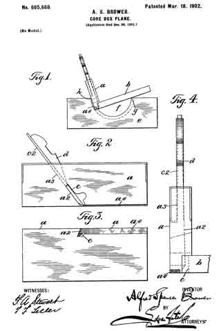
In the accompanying drawings, forming part of this specification, in which like letters of reference designate corresponding parts in the several views, Figure 1 is an end elevation of a plane embodying my invention and a core-box upon which it is in position to operate. Fig. 2 is a side elevation of the plane. Fig. 3 is an inverted plan view thereof. Fig. 4 is a front elevation, part of the base portion or guide of the plane being broken away.
In the practice of my invention I provide a device or tool of the class specified which comprises a body portion a, consisting of an oblong plate, and a base or guide portion b, also consisting of an oblong plate, said base or guide portion being preferably much wider than the body portion a and being secured to the bottom edge thereof at right angles thereto, the connection of the base or guide portion b with the body portion a being preferably made by countersinkiug said base or guide portion into the body portion, as is also indicated in Figs. 1 and 4. The body portion of the tool is also provided centrally of the bottom portion thereof with an inclined slot or groove a2, which communicates with an opening or passage a3, which extends upwardly and backwardly in line with said slot or opening and through the top portion of said body portion of the tool, and placed in the slot or opening a2 is a bit or cutter proper which is designated by the reference character c and which is provided with a shank c2, which passes upwardly through the opening or passage a3, and said bit or tool proper is held in place by a wedge d in the usual manner. The edge of the bit or cutter proper passes through the bottom of the slot or opening a2, as clearly shown in Fig. 2, and said bit or tool may be adjusted by means of the wedge d, as will be readily understood.
The body portion a of the plane is provided upon its under surface forwardly of the cutter c with a rabbet groove or kerf a4 of a depth equal to the customary or desired depth of the cut or shaving of the plane, which groove or kerf at its rear end communicates with the slot or opening a2. By reason of this rabbet groove or kerf a4 the cutter in its operative position ready to shave the wood lies in its relative projection below the roof of the said groove at a point corresponding to the normal level or surface of the base portion of the plane, and therefore that portion of the body or upright side which is at the rear of the plane is flush or on the same level with the edge of the cutter.
The operation of the device will be readily understood from the foregoing description, taken in connection with the accompanying drawings, and the advantages resultant from the use thereof will be manifest to all who are conversant with devices of this character.
In Fig. 1 of the drawings a core-box e is represented, and in practice the core-opening or segmental recess f in said box is roughly or partially hollowed out and the perfect cutting or planing out thereof is commenced on one side, and usually both sides of the recess are partially planed away a certain distance, so as to leave both perfect corners or edges of the recess open and free to the contact of the side of the plane therewith. The body of the tool is grasped by the hand in the usual manner and operated longitudinally, so as to cut away all remaining portions of the recess f in longitudinal shavings. In this operation the base or guide portion b rests on one edge g of the core-opening, while the body or side of the plane rests against the opposite edge h of the core-opening, and as the cutter c lies flush with the rear portion of the under surface of the body or upright side of the plane which rests upon the surface being cut the plane will be guided in a diametrically accurate manner to hollow out the core-box along an absolutely semicircular line to produce a perfectly sernicylindrical recess.
Having thus fully described my invention, what I claim as new, and desire to secure by Letters Patent, is —
1. A core-box plane comprising a body portion or frame formed of an angularly-connected or L-shaped side and base, and a cutter-blade projecting through the upright side of the plane, and a rabbet groove or kerf formed in the under surface of the plane which extends from the edge of the cutter to the front end of the body of the plane, and the rear portion of the said under surface lying dush with the edge of the cutter whereby in the planing of a core-box the base and side of the plane will be accurately disposed relatively to the cutter and to the core-box.
2. A core-box plane which is L-shaped in cross-section and the upright section of which is provided with a cutter which is passed therethrongh, said upright portion being provided in the bottom thereof with a rabbet groove or kerf which extends from the cutting edge of the tool to the front end of the body portion.
In testimony that I claim the foregoing as my invention I have signed my name, in presence of the subscribing witnesses, this 23d day of December, 1901.
ALFRED S. BROWER.
Witnesses:
F. A. STEWART,
F. F. TELLER.