
| PLEASE NOTE: The images presented on this page are of low resolution and, as a result, will not print out very well. If you wish to have higher resolution files then you may purchase them for only $2.95 per patent by using the "Buy Now" button below. All purchases are via PayPal. These files have all been cleaned up and digitally enhanced and are therefore suitable for printing, publication or framing. Each zip package contains all the images below (some packages may contain more), and purchased files can be downloaded immediately. |
United States Patent Office.
JOSEPH R. BAILEY, OF WOONSOCKET, RHODE ISLAND, ASSIGNOR TO
HIMSELF AND SELDEN A. BAILEY, OF SAME PLACE.
Letters Patent No. 105,766, dated July 26, 1870.
_________________
IMPROVEMENT IN BOX-SCRAPER.
_________________
The Schedule referred to in these Letters Patent and making part of the same.
_________________
To all whom it may concern:
Be it known that I, JOSEPH R. BAILEY, of Woonsocket, in the county of Providence, and in the State of Rhode Island, have invented a new and useful Improvement in Scrapers; and I do hereby declare that the following is a full, clear, and exact description thereof; reference being had to the annexed drawing making part of this specification, in which —
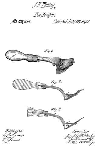
Figure 1 is a perspective view of the scraper.
Figure 2 is a longitudinal section thereof.
Figure 3 shows a scraper with the cap left off.
The same letters are used in all the figures to indicate identical parts.
This invention relates to that class of devices usually termed box or barrel-scrapers; and
My improvement consists in the application of an eccentric or curved rod for holding the bit in position; and, also, in combining with the bit and eccentric rod a cap or iron plate to be inserted between the two, for the purpose of holding the bit more firmly, as well as to prevent slipping of the same in turning the rod down to secure it, as will be more fully set forth in the following description and claim:
To enable those skilled in the art to make and use my invention, I will proceed to describe its construction and operation.
In the annexed drawing —
A represents the stock, terminating at one end in the shank a to enter the wooden handle A1, in which it is secured in the usual manner.
The other end of the stock is to be shaped substantially as shown, forming a frame, A2, for the reception of the bit, the transverse end af of which has the proper inclination to throw the bit, when inserted, into an advantageous position for cutting or shaving.
The lower end ofthe frame has a narrow throat, through which the edge of the bit projects and the shavings pass.
B is the bit, such as is now commonly used in planes.
The bit is secured in the frame by means of the rod C, which has its bearings in the sides of the frame, and, passing through one side, is turned upward at an angle terminating in a thumb-piece, c, by which to turn it.
By reference to fig. 1, it will be observed that the portion of the rod within the frame A2 is slightly curved, so that, when its handle is turned up to the position shown there, it will press upon the bit, or its cap, for the purpose of forcing such bit firmly against the end a’ of the frame, and thus hold it in position; said end a’ being made slightly concave upon its inner surface.
To hold the bit more firmly than can be done by the curved or eccentric rod alone, as well as to prevent slipping of the bit in seeming it by turning the rod, I provide a cap, D, a metallic plate to be inserted between the bit and rod, its lower edge being beveled, as shown. Although this cap is not an essential part of the scraper, I prefer in most cases to use it, for the reasons stated.
The principal advantage which this scraper possesses over others of the same type, consists in the fact that the bit, being not slotted, can be used up until it becomes too short to be secured.
What I claim as my invention, and desire to secure by Letters Patent, is —
The box-scraper, consisting of the frame A2 with a shank or handle, knife B, and curved or eccentric rod C for holding the latter in position, either with or without the cap D, substantially as described.
The above specification signed by
JOSEPH R. BAILEY.
Witnesses:
WALTER DUNKERLY,
CHARLES F. PAGE.