
| PLEASE NOTE: The images presented on this page are of low resolution and, as a result, will not print out very well. If you wish to have higher resolution files then you may purchase them for only $2.95 per patent by using the "Buy Now" button below. All purchases are via PayPal. These files have all been cleaned up and digitally enhanced and are therefore suitable for printing, publication or framing. Each zip package contains all the images below (some packages may contain more), and purchased files can be downloaded immediately. |
United States Patent Office.
CHARLES E. TUCKER, OF BOSTON, MASSACHUSETTS, ASSIGNOR TO
HIMSELF AND T. L. APPLETON, OF SAME PLACE.
Letters Patent No. 105,869, dated July 26, 1870
_________________
IMPROVEMENT IN CARPENTERS’ PLANES.
_________________
The Schedule referred to in these Letters Patent and making part of the same.
_________________
To all whom it may concern:
Be it known that I, CHARLES E. TUCKER, of Boston, in the county of Suffolk and State of Massachusetts, have invented certain new and useful Improvements in Carpenters’ Planes; and I do hereby declare that the following is a full and exact description thereof reference being had to the accompanying drawing and to the letters of reference marked thereon.
To enable others skilled in the art to make and use my invention, I will proceed to describe its nature, construction, and use.
The nature of my invention consists in the construction and arrangement of the parts composing my invention, as will he hereinafter fully described and set forth.
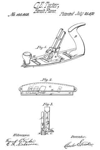
Figure 1 represents a perspective view of my invention.
Figure 2 is a plan, showing the under side of the plane.
Figure 3 is a cross-section of the plane.
The body of my plane consists, essentially, of two parts, C and C’, each of which parts have a downwardly projecting flange, H and H’; these two flanges together constitute the fence, and, being connected with the parts C C’, are adjustable in relation to each other.
This adjustment is effected by loosening the screws E and E’, fig. 1, which will allow the part C, to which the flange H is attached, to he moved, so that the flange H may be in contact with the flange H’, as shown in fig. 1, or may be at a distance from it, as shown in figs. 2 and 3.
The width of groove to be cut will depend upon the distance that the flanges H and H’ are from each other, and, as the flanges are adjustable, it will be seen that, with this plane, a groove of any width may he cut.
A and A’ are plane-irons attached to the parts B and B’ by set-screws S and S, as shown.
If desirable, a single iron may be used to take the place of the two irons A and A.
When a single iron is used it must be changed for each adjustment of the flanges H and H’, that is, for each width of groove required.
Each part of the plane is provided with a marker, one of which is shown at M, arranged as in an ordinary grooving-plane.
I am aware of the patent granted to T. Duvall, March 23, 1869, and therefore do not claim the features of his device.
What I claim as my invention, and desire to secure by Letters Patent of the United States, is —
The parts C C’, flanges H H’, set~screws E E’, parts B B’, and planing-knives A A’, when constructed and arranged substantially as shown and described.
CHARLES E. TUCKER.
Witnesses:
FRANK G. PARKER,
E. A. NICKERSON.