
| PLEASE NOTE: The images presented on this page are of low resolution and, as a result, will not print out very well. If you wish to have higher resolution files then you may purchase them for only $2.95 per patent by using the "Buy Now" button below. All purchases are via PayPal. These files have all been cleaned up and digitally enhanced and are therefore suitable for printing, publication or framing. Each zip package contains all the images below (some packages may contain more), and purchased files can be downloaded immediately. |
UNITED STATES PATENT OFFICE.
_________________
RUSSELL PHILLIPS, OF BOSTON, MASSACHUSETTS.
IMPROVEMENT IN CARPENTERS’ PLANES.
_________________
Specification forming part of Letters Patent No. 106,868, dated August 30, 1870.
_________________
To all whom it may concern:
Be it known that I, RUSSELL PHILLIPS, of Boston, in the county of Suffolk and Commonwealth of Massachusetts, have made an invention of a novel and useful implement which I term a Carpenter’s Combination-Plane; and I do hereby declare the following to be a full, clear, and exact description thereof, due reference being had to the accompanying drawings, making part of this specification, and in which —
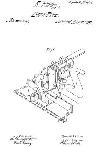
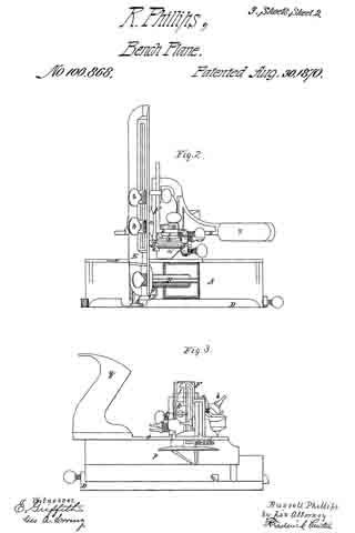
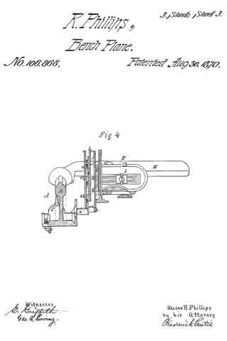
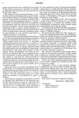
Figure 1 is a perspective view; Fig. 2, a plan; Fig. 3, a side elevation; Fig. 4, a vertical section.
This invention combines in one implement elementary features now only found in several independent tools, the result being a great saving in space in transportation, as well as in stores and carpenters’ shops, and enabling a mechanic to obtain, at small comparative cost and in a compact and efficient form, the substitutes for several classes of planes.
I have combined in this instrument a rabbeting-plane and an expansible matching-plane, to operate on and prepare boards of various thicknesses, one side of said rabbeting-plane serving as a fence or guide to the latter, as hereinafter explained.
While this invention consists, primarily, of the combination of a rabbeting-plane and an expansible matching-plane, the latter, in turn, will be found to consist of several members, so organized as to enable one to produce a “tongued groove-connection,” called “matching stuff,” a “cross-channel,” or a “plowed groove of any desired dimensions.”
In the drawings accompanying and illustrating this description of my invention, A denotes a rabbeting-plane, substantially of ordinary construction, with the exception of the removal of the handle, and the erection, at or about its center, of a post or standard, B, which slopes forward at a slight angle, and over the iron ofthe plane, which latter is represented at C. The plane A is further distinguished from others of its class by the addition to its under side of an adjustable gage, D, which converts it into a species of plane called “fillister,” or those in which the width of the rabbet cut by the tool is governed at pleasure.
The standard B supports from its upper part a long horizontal lateral bar or arm, E, departing from it at right angles to the length of the plane, such arm supporting the two movable cutter heads or stocks, which, with their adjuncts, constitute the expansible or variable matching-plane before alluded to, the arrangement of parts, as hereinafter explained, being such that both cutter-heads may be moved together or singly upon the arm and away from the rabbeting-plane A, or toward and away from each other thereupon, the side ofthe rabbeting-plane next adjacent to the said cutter-heads serving, under all circumstances, as a gage or “fence,’ so called, to the matching-plane.
The main or primary cutter-carrier is shown at F in the drawings as composed of a plate or portion, a, sliding upon or against the rear side of the arm E, and connned to such arm, upon which it slides, by clamp-nuts and bolts b b, or their equivalents, the inner end of the said plate a terminating in a right-angular bend or head, c, carrying upon its face the “spur or scoring iron,” such spur-iron a’ being secured in position thereupon by side projections or hooks, e e, and a set-screw, f, as represented, and performing the duties of preparing the way for either one or both of the matching cutters, as the case may be.
Upon the front or inner face of the cutter-carrier F or its cutter-head c, I apply a flat plate or second cutter-head, g, this latter object sliding vertically upon the head c, and being confined thereto by a set-screw or other device. The cutter-head g carries upon its inner face a cutter or iron, h, for cutting or plowing a groove, the relationship of the two cutter-heads being such that the head g may be lowered into a working position, or elevated above the same, while the cutter It may be raised or lowered with respect to its head, according to the depth of cut required, it being understood, as before stated, that when the said cutter (or its companion, to be duly referred to) is at work the side or fence i of the rabbeting-plane A serves as a guide or gage to determine the width of the cut thus made.
The iron or cutter It is composed of an upright flat plate, the lower part of which is bent into an angular sloping portion, which, constitutes its cutting-edge, the cutter by this means saving the necessity of employing two spurs to prepare its way, while the lower edge of the head g serves as a “sword,” so called, to determine the thickness of the shaving cut by the said cutter.
The cutter h, may be employed alone, in connection with the rabbeting-plane, to cut a channel, whether such groove be an ordinary cross-groove or the groove required to receive the tongue of the next adjacent board in “matching stuff,” or the said cutter may be employed in connection with the cutter to cut away one side of the tongue used in said operation of matching stuff; or, again, should occasion require, the cutter or iron h may be lowered and work in conjunction with the rabbeting-plane A, thus cutting at one and the same time a rabbet and groove or channel.
The second cutter, before mentioned, is shown at j in the accompanying drawings as mounted upon the inner face of a second cutter-head, k, which makes part of a carrier, l, mounted and sliding upon the first carrier, F, and confined thereto, by clamp-nuts or set-screws, in any proper manner, it being observed that the construction and relationship of this latter cutter-carrier and head with respect to the former being substantially the same as the former in respect to the arm or support E, before mentioned, it being observed that while the cutter or tool may be moved toward or away from the rabbeting-plane, for the purpose of cutting channels of varying width, the two cutters may be separated or contracted, in order to cut a tongue of any given width up to a certain extent.
Upon the outer or remote side ofthe second cutter-head, k, is disposed an adjustable gage for determining the depth of the cut made by either one or both the cutters h or j, (in connection with the rabbeting-plane as a side gage,) to produce a cross-channel or plow a groove.
As it becomes necessary to produce a sword to regulate the thickness of the shaving cut by the second cutter or iron, j, I form it (the sword) upon the under side of a fiat plate, o, which in turn is suspended from the under side of the carrier l, applied adjustably thereto, and confined in place by set-screws or their equivalents, in order that the lateral position of the said sword with respect to the said cutter j may be varied, as it sometimes becomes desirable that this sword shall travel in the center, or thereabout, of the groove or channel formed by such cutter.
Upon the upper side of the rear extremity of the sword, which is shown at p, or its supporting-plate o, I mount the handle of the combination-instrument, such handle being represented at q in the drawings.
An instrument constructed and organized as above explained may be used as a rabbeting-plane, or fillister simply.
By lowering the cutter h, to the proper extent and employing the side of the rabbeting-plane as a guide or gage, a cross-channel may be cut or a groove may be plowed.
By lowering the second cutter, j , and adjusting the distance between the two to the width of tongue required in machine-stuff, such tongue will be cut to any desired gage, or, as before stated, the second cutter, j, maybe employed alone, in connection with the spur-iron a’, to cut a channel or groove.
For extreme variations in the extent of cuts made by my present invention, I shall adapt cutters of varying widths; but it will be evident that considerable variations maybe made without removing the cutter at the time in use.
In the use of the rabbeting-plane alone, the cutter-head c should be inverted end for end to serve as a gage.
Although I have in the present instance represented one of the cutter-carriers as supported and sliding upon the arm E and the other carrier applied in similar manner to the first, I would remark that I intend applying each carrier by itself to the bed or frame of the tube.
I claim —
The herein-described carpenter’s plane.
RUSSELL PHILLIPS.
Witnesses:
EDW. GRIFFITH,
FRED. CURTIS.