| PLEASE NOTE: The images presented on this page are of low resolution and, as a result, will not print out very well. If you wish to have higher resolution files then you may purchase them for only $2.95 per patent by using the "Buy Now" button below. All purchases are via PayPal. These files have all been cleaned up and digitally enhanced and are therefore suitable for printing, publication or framing. Each zip package contains all the images below (some packages may contain more), and purchased files can be downloaded immediately. |
United States Patent Office.
TIMOTHY O. CALLAHAN, OF BOSTON, MASSACHUSETTS.
Letters Patent No. 107,757, dated September 27, 1870.
_________________
IMPROVEMENT IN PLANES.
_________________
Specification forming part of Letters Patent No. 107,757, dated December 18, 1870.
The Schedule referred to in these Letters Patent and making part of the same.
_________________
all to whom these presents shall come:
Be it known that I, TIMOTHY O. CALLAHAN, of Boston, in the county of Suffolk and State of Massachusetts, have made an invention of a new and useful Plane for Finishing Board Floors of Halls, Dwellings, Navigable Vessels, &c.; and do hereby declare the following to be a full, clear, and exact description thereof, due reference being had to the accompanying drawing making part of this specification, and in which —
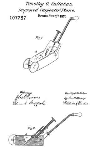
Figure 1 is a perspective view; and
Figure 2, a vertical, central, and longitudinal section of a plane embodying my improvements.
The stooping or crouching position now assumed, of necessity, by carpenters in planing or finishing board floors, and the time consumed in the act, have rendered the introduction of an implement similar to that herein explained of great value, the object to the accomplished being the construction of a plane that may be operated by a carpenter or laborer while in an ordinary erect walking position, the result being great economy of time, as well as lessening of fatigue on the part of the operator.
The invention consists —
First, in mounting a carpenter’s plane upon wheels or rollers, or a carriage supported upon wheels or rollers, in such manner that said plane may be easily propelled over the surface of a floor, while at work; and
Secondly, in providing a carpenter’s plane with an attenuated sloping handle, rising therefrom to such a height as to enable a person to readily grasp it, while in a standing position.
In the drawing which accompanies and constitutes part of this specification —
A represents a carpenter’s plane, the forward end of which is mounted upon wheels or rollers, b b, in order that it may be easily propelled along the floor, the rollers or their equivalents being of considerable weight, in order to insure the contact of the plane with the floor.
The iron of the plane is shown at c as confined within the throat or shaving-passage d of the plane, in part, by a screw, e, which passes through a slot, f formed centrally in the plane-iron, and screws into the rear wall of the throat d, and serves to clamp the iron to the plane.
The vertical adjustment of the plane-iron is effected by a long screw, g, which screws through a stud, h, connected to the rear side of the plane-iron, and at or near the upper part thereof, the lower end of the screw g being swiveled to a metallic plate, i, which is secured to the upper part of the plane, and in rear of its iron, the opposite or upper end of the screw being provided with a milled head, or its equivalent, by which it may be easily rotated.
The plane-iron c is not connected rigidly or immovably to the stud h before mentioned, but merely encompasses the same, consequently, by loosening the screw d, which clamps the iron to the plane, such iron may he instantly removed therefrom, free from any incumberance.
As before observed, the head of the screw g rises to such a position as to be readily seized by a workman while standing erect, or substantially so.
K in the drawing denotes an attenuated handle attached to the rear end of the plane A, and rising therefrom at an oblique angle in parallelism, or there about, with the screw g, which it should slightly overtop, and to such a height as will enable the workman, by its aid, to propel the plane over the surface of a floor in an ordinary walking position, with results and advantages before premised.
l have heretofore stated that the wheels b should possess suflicient gravity to maintain the plane in contact with the floor against irregular movements on the part of the workman, and I would here state that it may, in practice, be found desirable to add a movable weight to the forward end of the plane, in order to facilitate this object.
I would remark, further, that in place of the wheels b the plane may he mounted upon a vehicle or carriage, but I prefer, in practice, to constitute the plane its own vehicle, and the characteristic feature of my invention will be found to consist in providing a plane with a means of support by which the friction between it and the floor is greatly reduced, in addition to its prolonged handle.
As the wheels b or their equivalents are the only points of support or contact necessarily of the plane with respect to the floor, it results that the lower surface of the plane, from its throat rearward, may be sloping or curved, should such form, from any reason, be found necessary.
The merits of a plane provided with a means ol propulsion, as before stated, will be at once apparent to persons whose occupation, like my own, is that of planing floors.
The relief from the strain and unnatural position now, of necessity assumed, and the case and rapidity with which a floor may he planed hy means of my invention need no further comment.
I claim —
A carpenter’s plane, when provided with wheels or rollers and an elongated handle, K, all constructed in the manner and for the purpose herein specified.
TIMOTHY O. CALLAHAN.
Witnesses:
FRED CURTIS,
EDWARD GRIFFITH.


