
| PLEASE NOTE: The images presented on this page are of low resolution and, as a result, will not print out very well. If you wish to have higher resolution files then you may purchase them for only $2.95 per patent by using the "Buy Now" button below. All purchases are via PayPal. These files have all been cleaned up and digitally enhanced and are therefore suitable for printing, publication or framing. Each zip package contains all the images below (some packages may contain more), and purchased files can be downloaded immediately. |
UNITED STATES PATENT OFFICE.
_________________
WINSLOW B. GLOVER, OF BOSTON, MASSACHUSETTS.
IMPROVEMENT IN PLANES.
_________________
Specification forming part of Letters Patent No. 108,586, dated October 25, 1870.
_________________
To all whom it may concern:
Be it known that I, W. B. GLOVER, of Boston, in the county of Suffolk and State of Massachusetts, have invented a new and valuable Improvement in Planes; and I do hereby declare that the following is a full, clear, and exact description of the construction and operation of the same, reference being had to the annexed drawings, making a part of this specification, and to the letters and figures of reference marked thereon.
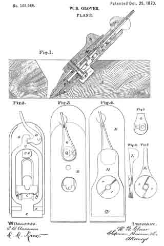
Figure 1 of the drawings is a representation of a central vertical longitudinal section of my invention. Fig. 2 is a front view of the bed-plate and slide. Fig. 3 is a front view of the plane-bit and its regulating-key. Fig. 4 is a front view of the binding-plate. Figs. 5, 6, and 7 are details.
My invention relates to planes; and it consists, mainly, in the construction and novel arrangement of devices, whereby the plane-bit can be regulated at will and with certainty.
The letter A of the drawings designates the plane-stock, of wood or iron. To this is fitted a bed-piece, B, which is secured firmly to the stock by means of screws a a.
Upon the bed-piece is arranged a slide, C, having a wedge-like end, c, which is pressed forward by the inclined portion e of the bed-piece when the slide is depressed, thereby advancing the plates which compose the plane-bit and lessening the throat-opening. When it is desired to widen the throat to admit larger shavings, the slide is drawn up by means of the lever D, pivoted to the bed-piece B, as shown. The slide is kept close to the bed-piece, when elevated, by means of its tongue c’, which is arranged to work in an inclined slot, l, in the bed-piece. The lever D therefore operates, through the slide C, to regulate the size of the throat or opening through which the shavings pass.
P designates the plane-bit, which is secured to its cap E by means of a screw in the ordinary manner. Through the cap E are formed two openings — one above the screw and the other below. A notch, v, is formed at the side of the upper opening, and in this notch works the toe n of the lever or key G, which is pivoted eccentrically on the pin s, formed on the shoulder F — a part ofthe bed-plate. The shoulder F also serves to keep the plane-bit right as it fits in the longitudinal slot thereof. By moving the handle of the lever G to the right the plane-bit is lowered, and, reversely, a movement to the left will elevate it.
The parts are bound together by the plate H, curved in form, and arranged so that its ends only bear upon the cap. A recess is formed in its upper end to receive the expanded end of the key G, and a circular depression is made in its face, the bottom of which is formed into two semicircular inclined planes, r r, arranged to operate in connection with two similar inclined planes, t t, formed on the under side of the binding-key K. This binding-key is secured to the bed-plate by means of the screw L, formed with a large head, which is passed through an opening in the bed-plate, having a notch or contraction, i, in its lower side. The head of the screw is moved downward in the direction of this notch until the neck is embraced by it. A slight turn of the key K, causing the inclined planes to act upon each other, will bind all the parts tightly together. In order to admit the head of the binding-screw, the wood of the stock is slightly excavated at U.
A plane constructed with the above appliances is capable of being operated in a satisfactory manner. No violence — as striking with a hammer or mallet — is needed. If the throat requires alteration, the binder is loosened by a turn of the key K, and the slide C then regulated by the lever D. A turn of the key K will make all tight again. The key G regulates the bite of the plane-bit, and on account of its great leverage will operate without the necessity of previously loosening the binder.
What I claim as my invention, and desire to secure by Letters Patent, is —
1. The lever or key G, pivoted to the bed-plate, and arranged to engage with the cap-iron E, thereby regulating the bite of the plane-bit, as specified.
2. The slide C, operated by means of the lever or key D, in combination with the bed-plate B, having an inclined plane, e, all constructed and arranged to regulate the size of the throat of the plane, as specified.
3. Attached to the bed-plate A, the cam-lever K, in combination with the semicircular inclined planes r r of the bent binding-plate H, all constructed to operate as specified.
4. The slide C, having tongue c’, in combination with a, bed-plate having an inclined slot, l, as speciiied.
5. The combination of the levers D, G, and K, plates B, E, and H, and slide C, all constructed and arranged to operate as specified.
In testimony that I claim the above I have hereunto subscribed my name in the presence of two witnesses.
WINSLOW B. GLOVER
Witnesses:
H. R. PHILBRICK,
R. M. LINDLEY.