
| PLEASE NOTE: The images presented on this page are of low resolution and, as a result, will not print out very well. If you wish to have higher resolution files then you may purchase them for only $2.95 per patent by using the "Buy Now" button below. All purchases are via PayPal. These files have all been cleaned up and digitally enhanced and are therefore suitable for printing, publication or framing. Each zip package contains all the images below (some packages may contain more), and purchased files can be downloaded immediately. |
UNITED STATES PATENT OFFICE.
_________________
LEONARD BAILEY, OF HARTFORD, CONNECTICUT.
IMPROVEMENT IN BENCH-PLANES.
_________________
Specification forming part of Letters Patent No. 189,415, dated April 10, 1877; application filed February 16, 1877.
_________________
To all whom it may concern:
Be it known that I, LEONARD BAILEY, of Hartford, in the county of Hartford and State of Connecticut, have invented certain new and useful Improvements in Bench-Planes; and I do hereby declare that the following is a full, clear, and exact description thereof, whereby a person skilled in the art can make and use the same, reference being had to the accompanying drawing, and to the letters of reference marked thereon.
Like letters in the figures indicate the same parts.
My improvement relates to such bench-planes as are provided with an adjustment for regulating the depth of cut while the bit remains set in the stock.
My invention has for its object a better means of accomplishing the adjustment of the cutting-edge of the bit or iron in the throat of the stock, so as to produce the desired result; and it consists in the mechanical combination and arrangement of the several parts, as will be hereinafter described, and as an improvement upon Letters Patent granted to me December 12, 1876, No. 185,280.
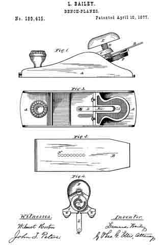
In the accompanying drawing, Figure 1 is a side view of my improved plane. Fig. 2 is a top view with the cap and bit removed, so as to show the top of the adjusting mechanism. Fig. 3 is a top view of the bit or iron removed from the stock. Fig. 4 is a view of the back or under side of the adjusting mechanism removed from the stock.
A is the stock. B is the bit or iron. C is a cap, corresponding to the wedge, for holding the bit in place. It is provided with ears which enter into slots in the stock, and its lower edge rests upon the bit. It is provided with the set-screw D, operated by the handle E, for clamping the bit firmly down upon its bed.
F is a milled head for operating the adjusting mechanism. It has the pinon G, which turns with it and gears into the wheel H. Both of these wheels turn upon axes fixed in the plate I.
The wheel H is provided with the cam-slot J, in which runs the stud K, which also passes through the plate I, which is furnished with a straight slot, and is attached to the link L. This link moves longitudinally in a groove in the upper side of the plate I, and lies immediately under and next to the bit B when it is in place. The stud M upon the lower end of the link enters into one of the holes N in the bit, and communicates motion to it from the cam-slot in the wheel H when the milled-headed wheel F is turned.
By means of my invention a regular and slow motion can be given to the bit to advance or withdraw it through the throat of the stock.
It will also be observed that on account of the multiplying wheels G and H, the cam can be made short, not to exceed a complete turn, so that it can be constructed with a variable inclination, and be of such a form that at any point an equal amount of turn in the head F will advance the bit an equal amount. This gives the user of the tool a better control over the movement of the cutting-edge, and enables him to set it exactly without waste of time.
What I claim as my invention is —
The combination of the longitudinally-slot ted bed-plate I, the link L, provided with the studs M K, the pinion G, and the gear-wheel H, having the cam-slot J, constructed to operate as shown and described, and for the purpose specified.
LEONARD BAILEY.
Witnesses:
THEO. G. ELLIS,
WILMOT HORTON.


