
| PLEASE NOTE: The images presented on this page are of low resolution and, as a result, will not print out very well. If you wish to have higher resolution files then you may purchase them for only $2.95 per patent by using the "Buy Now" button below. All purchases are via PayPal. These files have all been cleaned up and digitally enhanced and are therefore suitable for printing, publication or framing. Each zip package contains all the images below (some packages may contain more), and purchased files can be downloaded immediately. |


UNITED STATES PATENT OFFICE.
_________________
EDWIN WALKER, OF ERIE, PENNSYLVANIA.
ADJUSTABLE-FACED PLANE.
_________________
SPECIFICATION forming part of Letters Patent No. 318,331, dated May 19, 1885.
Application filed February 6, 1885. (No model.)
_________________
To all whom it may concern:
Be it known that I, EDWIN WALKER, a citizen of the United States, residing at Erie, in the county of Erie and State of Pennsylvania, have invented certain new and useful Improvements in Adjustable-Faced Planes; and I do hereby declare the following to be a full, clear, and exact description of the invention, such as will enable others skilled in the art to which it appertains to make and use the same, reference being had to the accompanying drawings, and to the letters of reference marked thereon, forming part of this specification.
My invention relates to improvements in plane-stocks and mechanism connected therewith; and it consists of the improvements hereinafter set forth and explained.
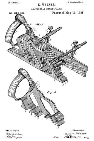
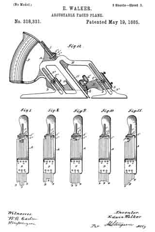
Figure 1 is a perspective view of my improved plane. Fig. 2 is a perspective view of my improved plane-stock frame with the adjustable plates and other mechanism thereof removed therefrom. Fig. 3 is a side elevation of the back half of my improved plane-stock with a portion of the adjustable plates removed, so as to show the bit-adjusting mechanism. Fig. 4 is a perspective view of one of the central adjustable plates, showing a groove therein for the bit-adjusting mechanism. Fig. 5 shows a front end view of my improved plane with a gage attached thereon for adjusting the depth of cut, and also showing the plane adjusted to a square-faced bit. Figs. 6, 7, 8, 9, 10, and 11 are front end views of my improved plane-stock, showing some of the forms to which the face of the plane-stock may be adjusted, (other portions of the mechanisms of the plane not being shown.) Fig. 12 is aside elevation showing a modified form of mechanism for securing the adjustable plates in place. Fig. 13 is a perspective view ofthe under side of a double-ended matching-bit, showing the holes for attaching the adjusting-rod thereto. Figs. 14 and 15 illustrate by perspective views some of the forms of bits to which the face of the plane-stock is adapted to be adjusted.
Like letters refer to like parts in all the figures.
In the construction of my improved plane, A is the frame, provided with the guides D D D D, adapted to receive and support vertically-adjustable longitudinal plates B B, &c., which plates B B, &c., together with the frame A, make up the plane-stock.
The guides D D D are provided with slots D’ D’ D’, in which clamps C C C operate, these clamps C C C being secured by thumb-screws C’ C’ C’, operating against the back side of the frame A. The frame A is also provided with ears I2 I2, between which the nut I’ of the bit-adjusting mechanism operates. The front guide D of the frame may also be provided with screws a a, &c., one for each of the plates B B, &c.
The frame A is preferably made of cast metal, except the handle F, which may be of wood.
The plates B B, &c., may be made either of cast metal or stamped out of sheet metal, and any number of the adjustable plates B may be used, according to the thickness which it is desired to make the plane-stock. The two outside plates B B, &c., may also be provided at their front ends with small adjustable cutters b b, inserted therein for cutting across the wood when the plane is used as a dado-plane, and for other purposes requiring such cutters.
The frame A is also provided with holes in the back side thereof, (not shown,) into which guide-rods J J can be inserted when it is desired to support a fence thereon. This fence K is connected to the slotted arms J ’ J’, which are attached to the sleeves J2 J2, which slide over the rods J J and are secured in place thereon by set-screws J3 J3, the fence K being adjustable up and down on the slotted arms J’J’ by means of bolts passing through the slots j j therein.
The bit H, I construct double-ended, so that either end may be used, according to the pattern desired, each end of the bit being made preferably of a different pattern. The bit is secured in place by means of the clip G and set-screw G’ therein, the clip G operating between the face of the bit and the lug E on the frame A.
For adjusting the bit H up and down, I provide an adjusting-rod, I,which has lugs i i on the lower end thereof adapted to fit into holes h h in the under face of the bit H, as shown in Figs. 3 and 13. This adjusting-rod I extends upward through grooves L in two of the central of the plates B B, &c. (Shown in Figs. 3 and 4.) Above the upper edges of the plates B B, &c., the adjusting-rod I is screw-threaded and provided with a thumb-nut, l’, which operates between the lugs I2 I2 on the frame A, so that by turning the nut the bit H may be adjusted up and down in the plane-stock.
Fig. 5 shows a depth-gage, M, which may be placed either upon the front guide-rod J, or, if desired, upon the front clamp C, behind the thumb-nut C’. This gage is provided with a slotted hole (not shown) by which it may be adjusted up and down to regulate the depth of cut made by the plane in dado-work and other work of that character. This gage M is also so arranged that it may be detached and taken off of the plane-stock when desired and not needed for use thereon.
The front cud views 5, 6, 7, 8, 9, 10, and 11 illustrate some of the forms to which the face of my improved plane-stock can be adjusted, bits being used corresponding with such adjustment, (the clamping mechanism which holds the plates to the frame A not being shown therein.)
In operating my improved plane the plates B B, &c., are each adjusted in the position desired and temporarily secured by the use of the set-screws a a, &c., in the front guide D of the plane-stock. These screws a a, &c., however, may be dispensed with, if desired, as they merely form a convenient means of securing each plate in place during the adjustment of the face of the plane-stock to any desired form of bit prior to the plates being finally secured (after adjustment) by the clamps C C C.
Any number of plates may be used in my improved plane, thereby making any width of face on the plane-stock desired.
I am aware that plane-stocks have been heretofore constructed of adjustable blocks, so constructed and arranged with relation to each other that the face of the plane-stock could be longitudinally adjusted to fit a circular surface — for example, the arc of a circle; but this construction is not capable of any lateral adjustment of the face of the plane-stock to suit different patterns of bit. I am also aware that plane-stocks have been constructed with detachable faces of different patterns, each pattern being suited to a particular form of bit made to match the pattern of the detachable face; but I am not aware of any construction of a plane-stock prior to my invention consisting of a frame supporting a series of thin longitudinal vertical plates, the lower edges of which plates combined formed the face of the plane-stock, and which plates were adapted to be vertically adjusted upon the supporting-frame, so that by such adjustment the face of the plane-stock could be altered laterally to adapt it to the use of any pattern of bit which the operator might have occasion to use in his work therewith. Therefore.
What I claim as new, and desire to secure by Letters Patent of the United States, is —
1. The combination, in a plane-stock, of a plane-stock frame with series of two or more vertical longitudinal plates which may be adjusted up and down upon said frame and clamped thereto, substantially as and for the purpose set forth.
2. In a plane-stock, the combination of a plane-stock frame provided with guides and clamping mechanism with a series of two or more vertical longitudinal plates the lower edges of which form the face ofthe plane-stock, said plates being vertically adjustable in said guides on the plane-stock frame, substantially as and for the purpose set forth.
3. The combination, in a plane stock, of a plane-stock frame and a series of two or more vertical longitudinal plates which may be adjusted upon and clamped to said frame, with removable fence-supporting rods and a fence adapted to be adjusted both vertically and laterally thereon, substautially as and for the purpose set forth.
4. In an adjustable-faced plane-stock, the combination of the plane-stock frame A, provided with the slotted lugs I2 I2 thereon, with the screw-threaded adjusting-rod I, the thumb-nut I’, operating between the lugs I2 I2, and the bit H, all operating together substantially as and for the purpose set forth.
5. In a plane-stock, the combination, with the plane-stock frame A and the vertically-adjustable longitudinal plates B B, of the set-screws a a, substantially as and for the purpose set forth.
6. In combination with a plane stock consisting of the plane-stock frame A and the vertically-adjustable longitudinal plates B B, the adjustable depth-gage M, substantially as and for the purpose set forth.
7. ln combination with a plane stock consisting of a plane-stock frame, A, and vertically-adjustable longitudinal plates B B, clamped thereto, adjustable cutters b b, substantially as and for the purpose set forth.
S. The combination, in a plane-stock, of a plane-stock frame, A, provided with guides D D D, clamps C C C, the vertically-adjustable longitudinal plates B B, the bit-securing mechanism E G G’, bit-adjusting mechanism I I’, and bit H, all constructed and operating together substantially as and for the purposes set forth.
In testimony whereof I affix my signature in presence of two witnesses.
EDWIN WALKER.
Witnesses:
H. M. STURGEON,
F. J. BASSETT.