
| PLEASE NOTE: The images presented on this page are of low resolution and, as a result, will not print out very well. If you wish to have higher resolution files then you may purchase them for only $2.95 per patent by using the "Buy Now" button below. All purchases are via PayPal. These files have all been cleaned up and digitally enhanced and are therefore suitable for printing, publication or framing. Each zip package contains all the images below (some packages may contain more), and purchased files can be downloaded immediately. |
UNITED STATES PATENT OFFICE.
_________________
JOSEPH VENDRAND, OF PARIS, FRANCE.
IMPROVEMENT IN PLANES.
_________________
Specification forming part of Letters Patent No. 35,719, dated June 24, 1862.
_________________
To all whom it may concern:
Be it known that I, JOSEPH VENDRAND, of Paris, in the Empire of France, have invented certain new and useful Improvements in Planes; and I do hereby declare that the following is a full and exact description thereof.
All persons accustomed to the use of hand-planes are acquainted with the difficulty of properly adjusting the plane-iron in the stock in such a manner as to give the perfect parallelism which must exist between the face of the plane and the edge of the iron, and to secure the perfect nicety of adjustment of the projection of the edge beyond the face of the plane, which is necessary for fine work.
The improvements which I have invented and for which I desire to obtain a patent obviate perfectly the inconveniences above stated.
They consist in the construction and arrangement of parts, hereinafter described, by which an additional regulation is attained, so as to preserve the parallel position of the cutting-edge with reference to the face of the plane, while it is raised or lowered by the adjusting-screw to adapt it to cut the proper thickness of shaving, and also in the construction and arrangement of parts for securing the plane-iron in position.
The regulator by which the plane iron is adjusted to the proper depth of cut, which is operated simply by the hand, does not sensibly complicate the plane, and it permits the regulation of the projection of the iron to the utmost nicety that may be desired.
For the purpose of facilitating the operation of the plane for persons who are not much habituated to its management, I in some cases cut away the wood of each of its sides in such a manner as to produce grooves sufficiently deep to permit it to be easily grasped when the workmen desires to raise the tool or to direct it to his fancy with greater ease.
The accompanying drawings will give a clear idea of the nature ofthe invention.
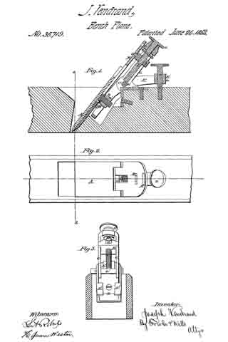
Figure 1 is a longitudinal vertical section of a plane constructed with my improvements. Fig. 2 is a plan of the same. Fig. 3 is a transverse vertical section showing the parts toward the rear end of the plane from the line 1 2, the plane-iron and cap being removed to give an unobstructed view of other parts.
The iron A is controlled by the tenon a, which is a part of the nut B, sliding on the support C, by means ofthe screw V, which is operated by the milled head v. The tenon a fits into a mortise, It, which is made transversely in the iron A and of sufficient length to allow the necessary lateral adjustment of the upper end of the iron to bring the edge parallel with the face of the plane.
The iron, regulated by means of the screw V, is retained in the position given it by the movable stirrup E, which oscillates on an axis, e’, in the fixed support C. For that purpose the stirrup or frame E is separated or divided in the lower part into two branches, upon which two parallel ears, E’, are formed, which ears take hold of the flange of the nut a’, Fig.
4, which binds the iron and cap together.
The stirrup E is operated to secure the plane-iron to its seat by means of screw e, which passes through the socket or eye E2, and rests at its lower end upon the head of a screw sunk in the top of the plane. By turning the screw e down upon this support the eye E2 is raised and the ears E’ conseqnently forced back so as to draw the plane-iron and cap down firmly against the wood, which supports them and retains them securely in position. In adjusting the iron it may be proper to slightly loosen the screw e to allow the iron to be moved with greater ease. The adjustment is then made by means of the screw V to any desired exactness. The first adjustment to be made, however, upon inserting the plane-iron is to get the edge perfectly parallel with the face of the plane, which the mode of connecting the plane-iron to the adjusting-screw by the elongated mortise and tenon on the nut in which the adjusting-screw works enables the operator to do satisfactorily. This adjustment once made, the plane-iron may be moved up and down without disturbing the parallelism of the edge with the face ofthe plane.
When it is desired to remove the plane-iron, the screw e should be turned back about three revolutions, which will give the necessary play between the ears E’ and the nut a’ to allow such removal.
The improvements which I have described may be applied with equal advantage to planes of every size and to planes for working rabbets, moldings, and cavettos.
I am aware that planes have been constructed in which the cutting-iron has been adjusted by raising and lowering it through the agency of a screw, without any means of lateral adjustment to secure perfect parallelism between the edge of the cutter and the face of the plane. I am also aware that a patent was granted to Thomas D. Worrall, August 4, 1857, in which a flange is represented attached to the plane iron, upon which flange a lever, hung upon an axis near the top of the stock and operated by a screw from the rear, is intended to operate to secure the cutter in position. The arrangement of parts is, however, different from that I have described, and involves objections in practical use which my invention avoids. The attachment of the flange adds expense and complication to the plane, While in my invention the nut which secures the cap to the cutter also furnishes the means of grasping and securing it in position. The arrangement of the screw for fastening the plane-iron back of the lever upon which it operates to secure said iron, as in Worrall’s plane, is also objectionable, because it involves complication of parts, and because it brings the head of the screw in the way of the right hand of the workman when operating the plane. These objections are avoided by my invention.
I claim–
1. The combination, with the plane-iron A, provided with mortises R, as described, of the adjusting-screw V, sliding block B, and tenon a, the said tenon and mortise being relatively so constructed as to allow the iron sufheient lateral play to permit the perfect adjustment ofthe edge parallel to the face of the plane, as set forth.
2. The combination of the nut a, which secures the cap to the cutting-iron, with the lever E and ears E’ E’, as and for the purpose set forth.
3. The arrangement of the lever E and screw e, as described — that is to say, in such a manner that the screw shall take its point of support upon the top of the plane and, extending up through the nut E2, terminate in a head for operating above the lever E, as set forth, instead of behind it, where it would be in the way of the operator.
In testimony whereof I have signed my name to this specification before two subscribing witnesses.
J. VENDRAND.
Witnesses:
E. RICHARD,
GEO. HUTTON.