
| PLEASE NOTE: The images presented on this page are of low resolution and, as a result, will not print out very well. If you wish to have higher resolution files then you may purchase them for only $2.95 per patent by using the "Buy Now" button below. All purchases are via PayPal. These files have all been cleaned up and digitally enhanced and are therefore suitable for printing, publication or framing. Each zip package contains all the images below (some packages may contain more), and purchased files can be downloaded immediately. |
UNITED STATES PATENT OFFICE.
_________________
LEVI SANFORD, OF SOLON, NEW YORK.
METHOD OF SETTING BITS IN BENCH-PLANES.
_________________
Specification of Letters Patent No. 3,838, dated November 26, 1844.
_________________
To all whom it may concern:
Be it known that I, LEVI SANFORD, of the town of Solon, in the county of Cortland and State of New York, have invented a new and useful Improvement in the Construction of Joiners’ Planes, by Which the Irons Are Adjusted by Screws for More or Less Bite, which is described as follows, reference being had to the annexed drawings of the same, making part of this specification.
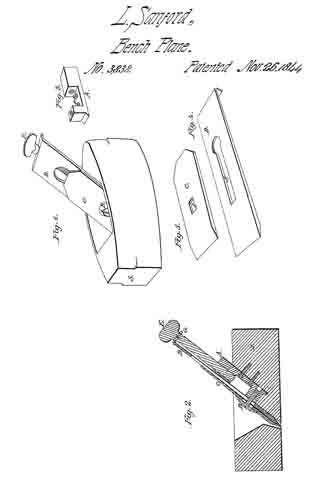
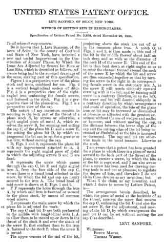
Figure 1 is a perspective view of the plane stock and irons, combined for use. Fig. 2 is a vertical longitudinal section of ditto. Fig. 3 is a perspective view of the right-angled iron containing the female screws, and fastened in the stock. Fig. 4 is a perspective view of the plane-iron. Fig. 5 is a perspective view of the cap.
The nature of my invention consists in securing to the back part of the throat of a plane stock S, by screws or otherwise, a right angled piece of metal A, which receives the screw B, for securing and setting the cap C, of the plane bit D, and a screw E, for setting the plane bit D, by which arrangement the bit can be set for a greater or less bite, without moving the cap.
D, Figs. 1 and 2, represents the plane bit with my improvement attached to it. A represents the right angled piece of metal to which the adjusting screws B and E are fixed.
B represents the screw which passes through the cap C, bit D and right angled iron A, from the face side of the cap C, where there is a broad head attached to the screw, by which the bit and the cap are firmly attached to the iron A. The broad head of said screw is shown at B, Figs. 1 and 2.
F F represents the holes through the iron A, by which said iron is fastened or secured to the plane stock, by means of common wood screws.
E represents the main screw by which the plane bit is adjusted for work.
The cap C and bit D are both perforated in the middle with longitudinal slots I, J, to allow them to be moved up or down in the throat of the stock S and over the shank of the screw B, that confines them to the iron A, fastened to the stock S, when the screw E is turned.
The upper corners of the end of the bit, projecting above the stock are cut off as in the common plane iron. A notch G, Figs. 1 and 2, is then made in this end of the bit in the middle thereof about half an inch deep and as wide as the diameter of the neck H of the screw E. This end of the bit is then bent down at right angles so as to enter the channel formed around the neck of the screw E will recede obliquely upward drawing with it the bit ; and by turning said screw in a contrary direction, or to the left, the screw and bit will descend obliquely in a contrary direction by which arrangment and mode of operation, the bite of the plane iron or bit may be increased or diminished at pleasure or adjusted with the greatest exactness without the use of wedges and mallet or hammer, and without moving the cap, the distance between the lower edge of the cap and the cutting edge of the bit being increased or diminished as the bite is increased or decreased. The cap and bit are otherwise made in the usual manner. Likewise the stock.
I am aware that a patent has been granted for a plane in which there is a piece of metal secured to the back part of the throat of the plane, to receive a screw, by which the bite of the bit is regulated, and I am also aware that a screw has been used for drawing cutting tools in and out at pleasure, to regulate the degree of bite, and therefore I do not claim these devices as my invention ; but
What I do claim as my invention and which I desire to secure by Letters Patent, is —
The arrangement herein described, by which the piece of metal at the backside of the throat, receives the screw that secures the cap C, embracing the bit D and also the set screw E, for the adjustment, and moving of the bit D, by which arrangement the said bit D can be set without moving the cap C as described.
LEVI SANFORD.
Witnesses:
EDWIN MAHER,
THOMAS WIBIRT.