
| PLEASE NOTE: The images presented on this page are of low resolution and, as a result, will not print out very well. If you wish to have higher resolution files then you may purchase them for only $2.95 per patent by using the "Buy Now" button below. All purchases are via PayPal. These files have all been cleaned up and digitally enhanced and are therefore suitable for printing, publication or framing. Each zip package contains all the images below (some packages may contain more), and purchased files can be downloaded immediately. |
UNITED STATES PATENT OFFICE.
_________________
WILLIAM S. LOUGHBOROUGH, OF ROCHESTER, NEW YORK.
IMPROVEMENT IN GROOVING OR PANEL PLOWS.
_________________
Specification forming parts of Letters Patent No. 42,585, dated May 3, 1864.
_________________
To all whom it may concern:
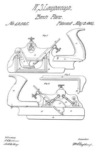
Be it known that I, WM. S. LOUGHBOROUGH, of Rochester, in the county of Monroe and State of New York, have invented a new and useful Panel-Plow or Grooving-Plane; and I do hereby declare that the following is a full, clear, and exact description thereof, reference being had to the accompanying drawings, making a part of this specilication, in which —
Figure 1 is an elevation of the left side of the plane. Fig. 2 is an elevation of the right side. Fig. 3 is an end view of the fence B detached, showing the front arm, C.
Similar letters of reference indicate corresponding parts in the several figures.
The nature of my invention consists, mainly, in the peculiar construction of the stock of panel-plows or other grooving-planes ; also, in a novel and efficient means for securing the adjustment of the fence by simply turning one screw, and in an improved manner of securing the bits in this class of planes.
A in the drawings represents the skeleton stock; B, the fence; C and C’, the arms; D, the thumb-screw ibr fastening the bit; E, the screw for fastening the arms of the fence; a, the screw for holding the stop S ; G, the bit ; b and b’, the clamping-bars, and w the wedge, which is operated upon by the screw E, by which it is driven down between the end of the bars b and b’, causing them to clamp firmly against the arms of the fence and to hold it securely in position. The wedge should be made sufficiently obtuse to cause it to recede from between the bars whenever relieved by the screw.
The body or stock A of the plane is made, as seen in the drawings, with an enlargement, d, running diagonally across and projecting equally on each side. Within this enlargement is formed a mortise, through which the bit G is placed. This mortise should be five-eighths to three-fourths of an inch wide, and it is recessed on the front or upper side, as indicated by the dotted lines, which is done by enlarging the core. Said core should also have a projection on the right side, near the lower end, to form the opening under the clasp f for the bar b1’ to pass through. The clasp g is formed by “coping out” in molding, part ofthe stop being removed, as seen in Fig. 1, to show the recess. The oval-shaped recess in which the wedge w is placed is formed in the same manner, and is made deep enough to receive the upper end of the bars b and b’ and the thickness of the flange i. The clasp g is extended over the upper rib of the arm G, and a similar bearing is provided over C’ by the projection a. These bearings prevent the arms from “tilting” when released by the screw E. The projections J should be long enough to prevent any cramping of the arms when the fence is being moved either way, and also to secure its parallel movement, it being cast or otherwise rigidly fixed to the arms.
The stop S is secured between the diagonal ribs r by the screw a, which may have a milled head, if desired. The ribs r are cast with the stock, and they receive all the diagonal strain coming upon the stop, thereby relieving the screw a from all lateral strain. The stock A is thickened by the button u (seen in Fig. 2) to increase the threaded bearing ofthe screw a.
The arch N of the throatway may be formed on either side ofthe stock, but the right hand side is probably preferable.
The bits G are made of uniform thickness from end to end, and are provided, the same as other plow-bits, with a central groove in the back side, which rides the front end of the rear plate, P’, and they are so fitted in the mortise as to have a bearing at t before they strike the rest at v, against which they are forced by the screw D and firmly held. This manner of fitting the bits, always effecting a perfect bearing of the bit at t, whether a wide or narrow one is used, insures the discharge of the shavings.
The plate p projects each side across the stock so as to form the seat for the handle H centrally behind the bit. The handle is held against the side plate, lt, by the screw s, and the rear end is firmly held in position by a screw through the base plate p at y.
The fence B may be removed at any time without deranging the clamping devices, the flange i of the wedge to preventing the end of the bars b and b’ from falling out. There is a shoulder on the back side of b’ at e, Fig. 2, which strikes against the case of the bit-mortise, and thus prevents the bar from dropping away from the flange i, and b is kept in position longitudinally by the point c resting against the stock.
If desired, the arms G and C’ may be made separate from the fence B and attached thereto by screws or otherwise; but I prefer to cast them together, as shown in the drawings.
Among the many advantages afforded by making these tools of metal instead of wood are the following: They are much less cumber-some, are more durable, the parts are much more readily and perfectly adjusted, they work better and easier, because they never choke or clog with the shavings, and they can be sold for less than one-half the cost of wooden planes of the same variety.
The plates P and P’ are cast on the stock A, thereby avoiding the labor and expense of fitting and attaching them by screws or other-wise.
What I claim as my invention, and desire to secure by Letters Patent, is —
1. The above-described panel plow or plane, when constructed, arranged, and combined in the manner and for the purposes specified, as a new article of manufacture.
2. Securing the gage of the fence B at any desired point by operating a single screw, E, substantially in the manner specified.
WM. S. LOUGHBOROUGH.
Witnesses:
A. C. DICKINSON,
A. H. BILLINGS.