
| PLEASE NOTE: The images presented on this page are of low resolution and, as a result, will not print out very well. If you wish to have higher resolution files then you may purchase them for only $2.95 per patent by using the "Buy Now" button below. All purchases are via PayPal. These files have all been cleaned up and digitally enhanced and are therefore suitable for printing, publication or framing. Each zip package contains all the images below (some packages may contain more), and purchased files can be downloaded immediately. |
UNITED STATES PATENT OFFICE.
_________________
EMANUEL W. CARPENTER, OF LANCASTER, PENNSYLVANIA.
METHOD OF CONSTRUCTING THE SCREW-ARMS FOR ALL KINDS OF PLANES REGULATED WITH SCREW-ARMS.
_________________
Specification of Letters Patent No. 594, dated February 6, 1838.
_________________
To all whom it may concern:
Be it known that I, EMANUEL W. CARPENTER, of the city of Lancaster, State of Pennsylvania, have invented a new and useful improvement in the mode of regulating plow-planes, tongue and grooves, fillisters, and such other planes as are regulated by screw-arms; and I do hereby declare that the following is a full and exact description.
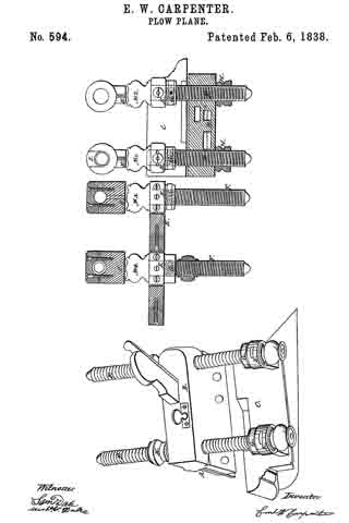
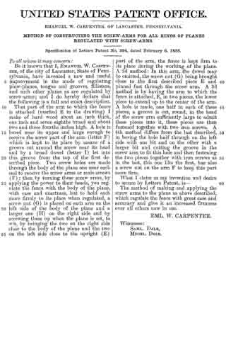
That part of the arm to which the fence is attached (marke E in the drawing) I make of hard wood about an inch thick, one inch and seven eighths broad and about two and three fourths inches high. A hole is bored near its upper edge large enough to receive the screw part of the arm (letter F) which is kept to its place by means of a groove cut around the screw near its head and by a broad dowel (letter I) let into this groove from the top of the first described piece. Two screw holes are made through the body of the plane one near each end to receive the screw arms or male screws (F) ; then by turning these screw arms, by applying the power to their heads, you regulate the fence with the body of the plane, with ease and exactness, but to hold each more firmly to its place when regulated, a screw nut (G) is placed on each arm on the left side of the body of the plane and a larger one (H) on the right side and by screwing these up when the plane is set, to wit, by bringing the two on the right side close to the body of the plane and the two on the left side close to the upright (E) part of the arm, the fence is kept firm to its place during the working of the plane. A 2d method : In this arm, the dowel may be omitted, the screw nut (G) being brought close to the first described piece E and pinned fast through the screw arm. A 3d method is by having the arm to which the fence is attached, E, in two pieces, the lower piece to extend up to the center of the arm. A hole is made, one half in each of these pieces, a groove is cut, round, in the head of the screw arm sufficiently large to admit these pieces into it, these pieces are then fastened together with two iron screws. A 4th method differs from the last described, in boring the hole half through on the left side with one bit end and on the other with a larger bit and cutting the groove in the screw arm to fit this hole and then fastening the two pieces together with iron screws as in the last, this one like the first, has also a screw nut on the arm F to keep this part more firm.
What I claim as my invention and desire to secure by Letters Patent, is —
The method of making and applying the screw arms to the plane as described, which regulate the fence with great ease and accuracy and give it an increased firmness over all others now in use.
EML. W. CARPENTER.
Witnesses:
SAML. DALE,
MICHL. DALE.