
| PLEASE NOTE: The images presented on this page are of low resolution and, as a result, will not print out very well. If you wish to have higher resolution files then you may purchase them for only $2.95 per patent by using the "Buy Now" button below. All purchases are via PayPal. These files have all been cleaned up and digitally enhanced and are therefore suitable for printing, publication or framing. Each zip package contains all the images below (some packages may contain more), and purchased files can be downloaded immediately. |
UNITED STATES PATENT OFFICE.
_________________
WILLIAM H. BLYE, OF DE RUYTER, NEW YORK.
PLANE FOR BEVEL EDGES.
_________________
Specification of Letters Patent No. 6,304, dated April 10, 1849
_________________
To all whom it may concern:
Be it known that I, WILLIAM H. BLYE, of De Ruyter, in the county of Madison and State of New York, have invented a new and useful Improvement in Planes for Working in Wood, of which the following is a full and exact description, reference being had to the annexed drawings of the same, making part of this specification, in which —
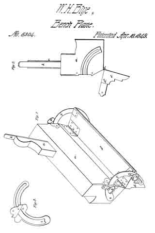
Figure 1 is a perspective view, Fig. 2. is an end elevation, and Fig. 3 is a view of the graduating arm or brace, and the guard plate, which secures the same to the end of the plane stock.
The same letters refer to the same parts in all the figures.
The nature of my invention, and improvement consists, in attaching an adjustable hinged guard or fence, to rabbet, fillister, molding, or other planes, by means of which the workman is enabled to bevel the edges of a piece of wood, in a uniform manner, and at any given angle.
In the accompanying drawings (a) represents the plane-stock which is made of wood, and of any required form and size.
(b) is the plane iron, (c) the wedge, which holds the iron in its place, (d) the guard or fence, is of the same length as the stock, and has one plane side which is about the same width as the face of the plane. From its uipper edge a rib (d2) is placed, for the purpose of stiffening the guard, and supporting the outer end of the braces, the outer, and under side of the rib and the lower edge, and back of the guard, may be ornamented with moldings, as represented, or otherwise, or may be left plain, according to the taste of the constructor: this guard is joined to the stock by hinges (e, e) which allow it to turn through an arc of about 100°, which admits of sufficient variation for most purposes, but in any case where greater variation, in the adjustment may become necessary, the hinges, and other parts concerned, can be so constructed, and arranged, as to allow the guard to turn through a longer arc. The braces (g) are of metal, and in the form of segments of a flat ring whose center is the axis of the hinge, the outer end of these braces have slots in them, through which the thumb screvv (h passes into the ends of the guard, to clamp it to the brace, these slots, also admit of the guard being turned to any extent within the limits of their length, to change the angle at which it stands to the face of the plane, and when the slots are too short, to admit of all the variation required, the ends of the braces are drawn out of the hole, formed in the end of the plate (i) and in the wood under the plate, and when placed in the proper position they are clamped firmly by the thumb screws (k k). Graduated scales of degrees may be formed upon the braces to denote the angle at which the guard may be placed.
The several parts of the plane above described may be made of wood, or metal, and arranged in a great variety of ways, without departing from the principle. of the invention, but these several modes, consist of devices well known to mechanics, and I therefore deem it unnecessary here to describe them.
The operation of this plane, is similar to that of others, the guard being adjusted to the required angle, is placed against the side of the piece, and held there firmly while the face of the plane is applied to the edge of the piece of wood, being pressed down upon it and at the same time pushed forward, the edge of the iron penetrates the wood to the depth which it projects through the face of the plane, and removes a shaving of that thickness — this operation is repeated until the piece is reduced to the required form.
What I claim as my invention and desire to secure by Letters Patent is,
The manner herein described of planing the edges of pieces of wood of a beveled form at given uniform or varying angles, by means of an adjustable guard hinged to the plane stock.
In testimony whereof I have hereunto signed my name.
WILLIAM H. BLYE.
Witnesses :
Z. T. BENTLEY,
A. V. BENTLEY.